

Ikea IMH16XSQ3, IMH16XSQ4, IMH16XSS3, IMH16XSS4, IMH16XVQ1 Installation Guide
...
MICROWAVE HOOD COMBINATION
INSTALLATIONINSTRUCTIONS
This product is suitable for use above electric or gas cooking products up to and including 36" (91.4 cm) wide. See "Installation
Requirements" section for further notes.
These installation instructions cover different models. The appearance of your particular model may differ slightly from the illustration in
these installation instructions.
INSTRUCTIONS.D'INSTALLATION
DEL'ENSEMBLEFOURA MICRO-ONDES/HOTTE
Ce produit est con(_u pour I'utilisation au-dessus d'appareils de cuisson electriques ou & gaz de 36" (91,4 cm) de largeur ou moins. Voir la
section "Exigences d'installation" pour d'autres remarques.
Ces instructions d'installation sont valables pour plusieurs modeles. II se peut que I'apparence de votre propre modele soit legerement
differente de celle montree sur les illustrations dans ce document.
Table of Contents / Tabledes mati@res
MICROWAVE HOOD COMBINATION SAFETY ....................... 1
INSTALLATION REQUIREMENTS ............................................ 2
Tools and Parts ......................................................................2
Remove Cardboard Template ............................................... 2
Location Requirements .......................................................... 2
Product Dimensions ............................................................... 3
Electrical Requirements ......................................................... 3
INSTALLATION INSTRUCTIONS .............................................. 4
Remove Mounting Plate ......................................................... 4
Rotate Blower Motor .............................................................. 4
Locate Wall Stud(s) ................................................................ 6
Mark Rear Wall ....................................................................... 7
Drill Holes in Rear Wall ........................................................... 7
Attach Mounting Plate to Wall ............................................... 8
Prepare Upper Cabinet .......................................................... 8
Install Damper Assembly ....................................................... 9
Install the Microwave Oven .................................................... 9
Complete Installation ........................................................... 10
VENTING DESIGN SPECIFICATIONS ................................... 11
ASSISTANCE ........................................................................... 12
Replacement Parts ............................................................... 12
Accessories .......................................................................... 12
SECURITE DE L'ENSEMBLE FOUR .&.MICRO-ONDES/HOTTE...13
EXIGENCES D'INSTALLATION ......................................................... 13
Outillage et pieces ........................................................................... 13
Deposer du gabarit de carton ......................................................... 14
Exigences d'emplacement .............................................................. 14
Dimensions du produit .................................................................... 14
Specifications electriques ............................................................... 15
INSTRUCTIONS D'INSTALLATION .................................................. 15
Depose de la plaque de montage ................................................... 15
Reorientation du moteur du ventilateur .......................................... 15
Identifier la position du/des poteau(x) du colombage mural .......... 17
Trace sur lemur arriere ................................................................... 18
Pergage de trous dans lemur arriere .............................................. 19
Fixation de la plaque de montage sur lemur ................................. 19
Preparation du placard mural .......................................................... 20
Installation du module du clapet anti-reflux .................................... 20
Installation du four & micro-ondes .................................................. 21
Achever I'installation ........................................................................ 22
SPECIFICATIONS DU CIRCUIT D'EVACUATION ........................... 23
ASSISTANCE ...................................................................................... 24
Pieces de rechange ......................................................................... 24
Accessoires ..................................................................................... 24
MICROWAVE HOOD COMBINATION SAFETY
Your safety and the safety of others are very important.
We have provided many important safety messages in this manual and on your appliance. Always read and obey all safety
messages.
This is the safety alert symbol.
This symbol alerts you to potential hazards that can kill or hurt you and others.
All safety messages will follow the safety alert symbol and either the word "DANGER" or "WARNING."
These words mean:
You can be killed or seriously injured if you don't immediately
follow instructions.
You can be killed or seriously injured if you don't follow
instructions.
All safety messages will tell you what the potential hazard is, tell you how to reduce the chance of injury, and tell you what can
happen if the instructions are not followed.
W10238255A
INSTALLATIONREQUIREMENTS
t'O0_S 3_J
Tools Needed
Gather the required tools and parts before starting installation.
Read and follow the instructions provided with any tools
listed here.
• Measuring tape • Stud finder
• Pencil • 7/16" socket wrench
• Masking tape or thumbtacks lag screws
• Scissors
• No. 2 Phillips screwdriver bit for wood or metal
• No. 3 Phillips screwdriver for
1/4-20 x 3" bolts • Keyhole saw
• Electric drill • Caulking gun and
• 3/16" (5 mm), 3/8" (10 mm) compound
drill bits
• 3/4" (19 mm) hole saw
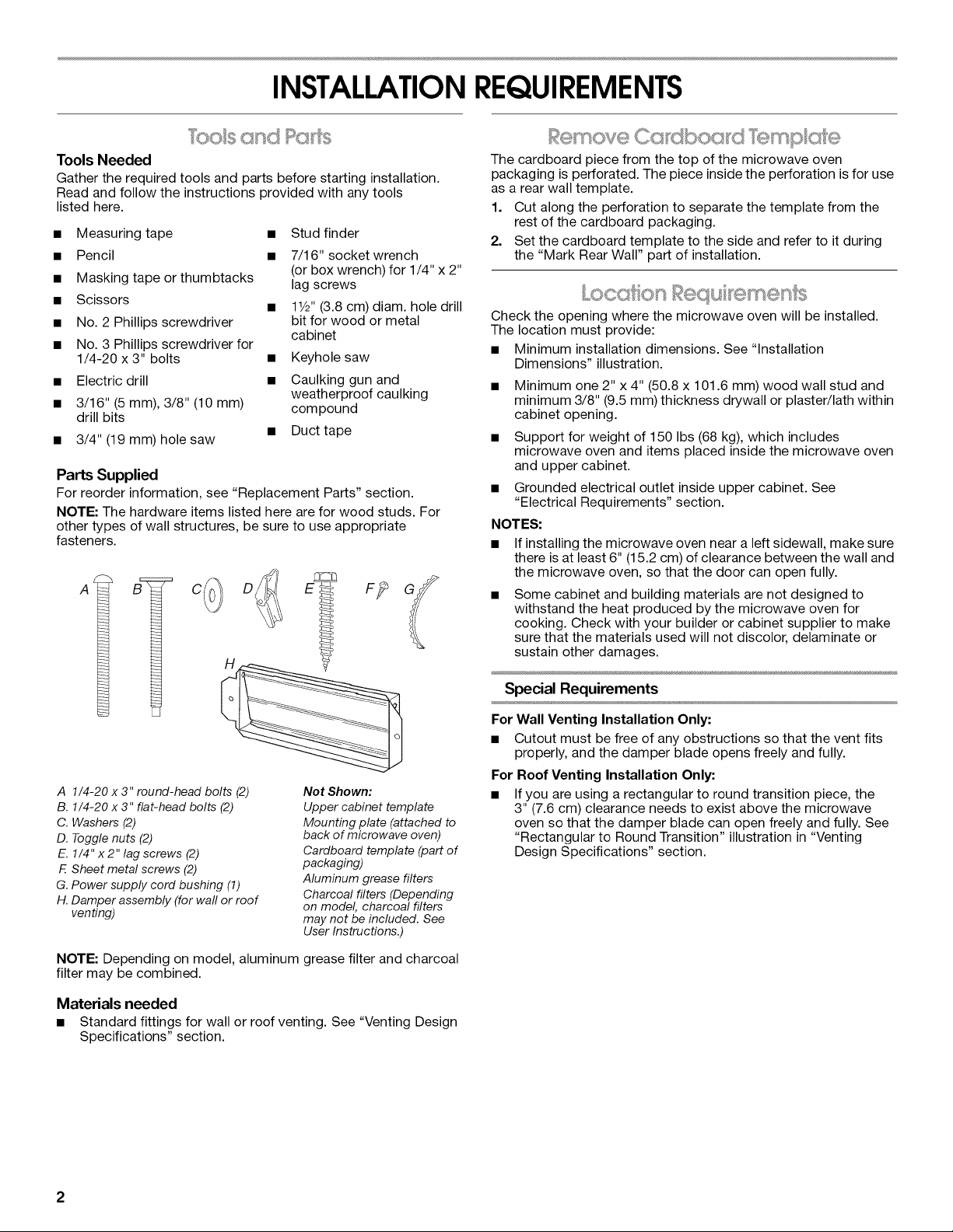
Parts Supplied
For reorder information, see "Replacement Parts" section.
NOTE: The hardware items listed here are for wood studs. For
other types of wall structures, be sure to use appropriate
fasteners.
(or box wrench) for 1/4" x 2"
• 11/2'' (3.8 cm) diam. hole drill
cabinet
weatherproof caulking
• Duct tape
The cardboard piece from the top of the microwave oven
packaging is perforated. The piece inside the perforation is for use
as a rear wall template.
1. Cut along the perforation to separate the template from the
rest of the cardboard packaging.
2. Set the cardboard template to the side and refer to it during
the "Mark Rear Wall" part of installation.
Check the opening where the microwave oven will be installed.
The location must provide:
• Minimum installation dimensions. See "Installation
Dimensions" illustration.
Minimum one 2" x 4" (50.8 x 101.6 mm) wood wall stud and
minimum 3/8" (9.5 mm) thickness drywall or plaster/lath within
cabinet opening.
Support for weight of 150 Ibs (68 kg), which includes
microwave oven and items placed inside the microwave oven
and upper cabinet.
Grounded electrical outlet inside upper cabinet. See
"Electrical Requirements" section.
NOTES:
• If installing the microwave oven near a left sidewall, make sure
there is at least 6" (15.2 cm) of clearance between the wall and
the microwave oven, so that the door can open fully.
Some cabinet and building materials are not designed to
withstand the heat produced by the microwave oven for
cooking. Check with your builder or cabinet supplier to make
sure that the materials used will not discolor, delaminate or
sustain other damages.
A 1/4-20 x 3" round-head bolts (2)
B. 1/4-20 x 3" flat-head bolts (2)
C. Washers (2)
D. Toggle nuts (2)
E. 1/4" x 2" lag screws (2)
F. Sheet metal screws (2)
G. Power supply cord bushing (1)
H. Damper assembly (for wall or roof
venting)
Not Shown:
Upper cabinet template
Mounting plate (attached to
back of microwave oven)
Cardboard template (part of
packaging)
Aluminum grease filters
Charcoal filters (Depending
on model, charcoal filters
may not be included. See
User Instructions.)
NOTE: Depending on model, aluminum grease filter and charcoal
filter may be combined.
Materials needed
• Standard fittings for wall or roof venting. See "Venting Design
Specifications" section.
Special Requirements
For Wall Venting Installation Only:
• Cutout must be free of any obstructions so that the vent fits
properly, and the damper blade opens freely and fully.
For Roof Venting Installation Only:
• If you are using a rectangular to round transition piece, the
3" (7.6 cm) clearance needs to exist above the microwave
oven so that the damper blade can open freely and fully. See
"Rectangular to Round Transition" illustration in "Venting
Design Specifications" section.
2
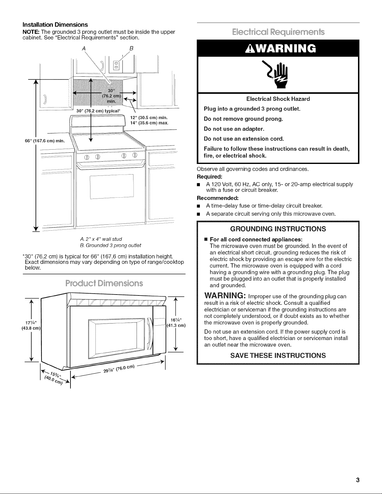
Installation Dimensions
NOTE: The grounded 3 prong outlet must be inside the upper
cabinet. See "Electrical Requirements" section.
A B
30" (76.2 cm) typicam*
12" (30.5 cm) rain.
14" (35.6 cm) max.
66" (167.6 cm) rain.
*30" (76.2 cm) is typical for 66" (167.6 cm) installation height.
Exact dimensions may vary depending on type of range/cooktop
below.
T
17¼"
(43.8 crn]
l ......
T
16¼"
_,1.3 cm)
Electrical Shock Hazard
Plug into a grounded 3 prong outlet.
Do not remove ground prong.
Do not use an adapter.
Do not use an extension cord.
Falure to folow these instructions can result in death,
fire, or electrical shock.
Observe all governing codes and ordinances.
Required:
• A 120 Volt, 60 Hz, AC only, 15- or 20-amp electrical supply
with a fuse or circuit breaker.
Recommended:
• A time-delay fuse or time-delay circuit breaker.
• A separate circuit serving only this microwave oven.
GROUNDING iNSTRUCTiONS
[] For all cord connected appliances:
The microwave oven must be grounded. In the event of
an electrical short circuit, grounding reduces the risk of
electric shock by providing an escape wire for the electric
current. The microwave oven is equipped with a cord
having a grounding wire with a grounding plug. The plug
must be plugged into an outlet that is properly installed
and grounded.
WARNING: Improper use of the grounding plug can
result in a risk of electric shock. Consult a qualified
electrician or serviceman if the grounding instructions are
not completely understood, or if doubt exists as to whether
the microwave oven is properly grounded.
Do not use an extension cord. If the power supply cord is
too short, have a qualified electrician or serviceman install
an outlet near the microwave oven.
SAVETHESEINSTRUCTIONS
INSTALLATIONINSTRUCTIONS
Depending on your model, the mounting plate may be in the foam
packaging, or it may be attached to the back of the microwave
oven.
NOTE: To avoid possible damage to the work surface, cover the
work surface.
1. Remove any remaining contents from the microwave oven
cavity.
2. If the mounting plate is attached to the back of the microwave
oven, remove it and set it aside.
3. Tape the microwave oven door closed so that door does not
swing open while the microwave oven is being handled.
NOTE: To avoid damage to the microwave oven, do not grip or
use the door or door handle while the microwave oven is being
handled.
The microwave oven is set for recirculation installation. For wall or
roof venting, changes must be made to the venting system.
NOTE: Skip this section if you are using recirculation installation.
Keep the damper assembly in case the venting method is
changed, or the microwave oven is reinstalled in another location
where wall or roof venting may be used.
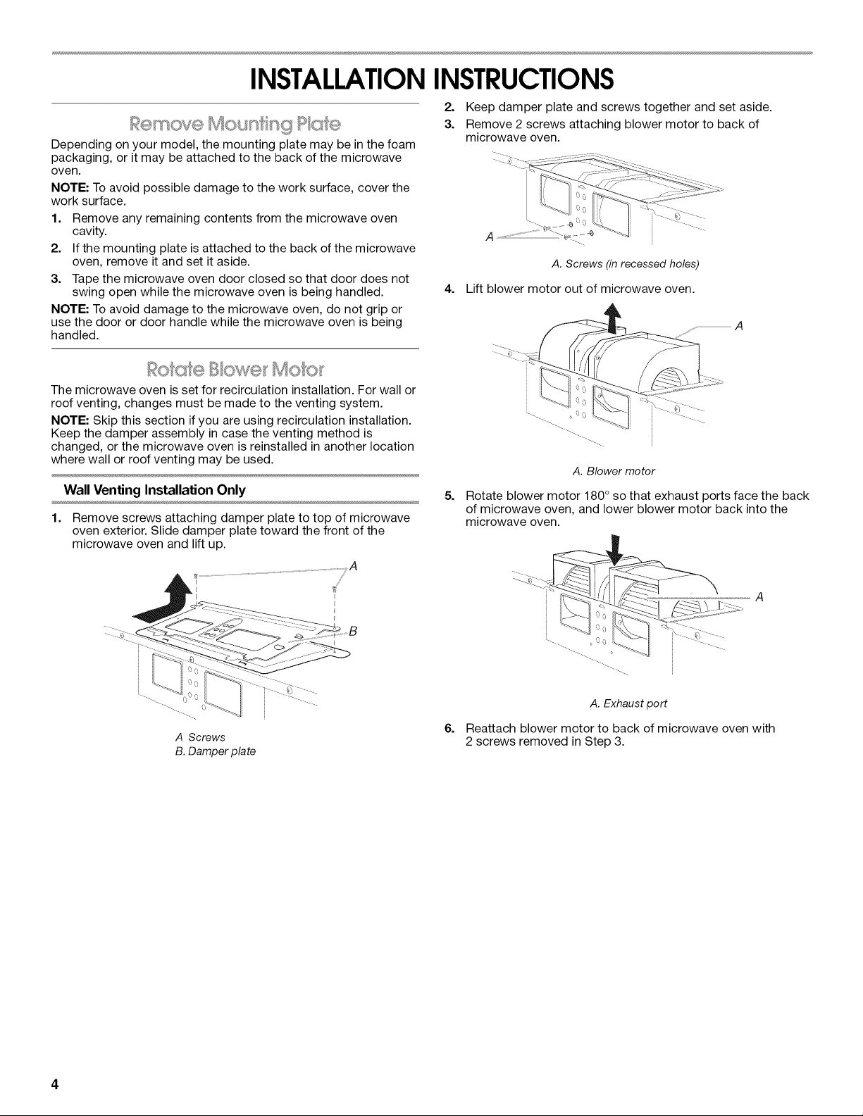
Wall Venting Installation Only
1. Remove screws attaching damper plate to top of microwave
oven exterior. Slide damper plate toward the front of the
microwave oven and lift up.
2. Keep damper plate and screws together and set aside.
3. Remove 2 screws attaching blower motor to back of
microwave oven.
.... t{
A. Screws (in recessedholes)
4,
Lift blower motor out of microwave oven.
A. Blower motor
5.
Rotate blower motor 180 ° so that exhaust ports face the back
of microwave oven, and lower blower motor back into the
microwave oven.
A Screws
B. Damper plate
A
A. Exhaustport
6. Reattach blower motor to back of microwave oven with
2 screws removed in Step 3.
4
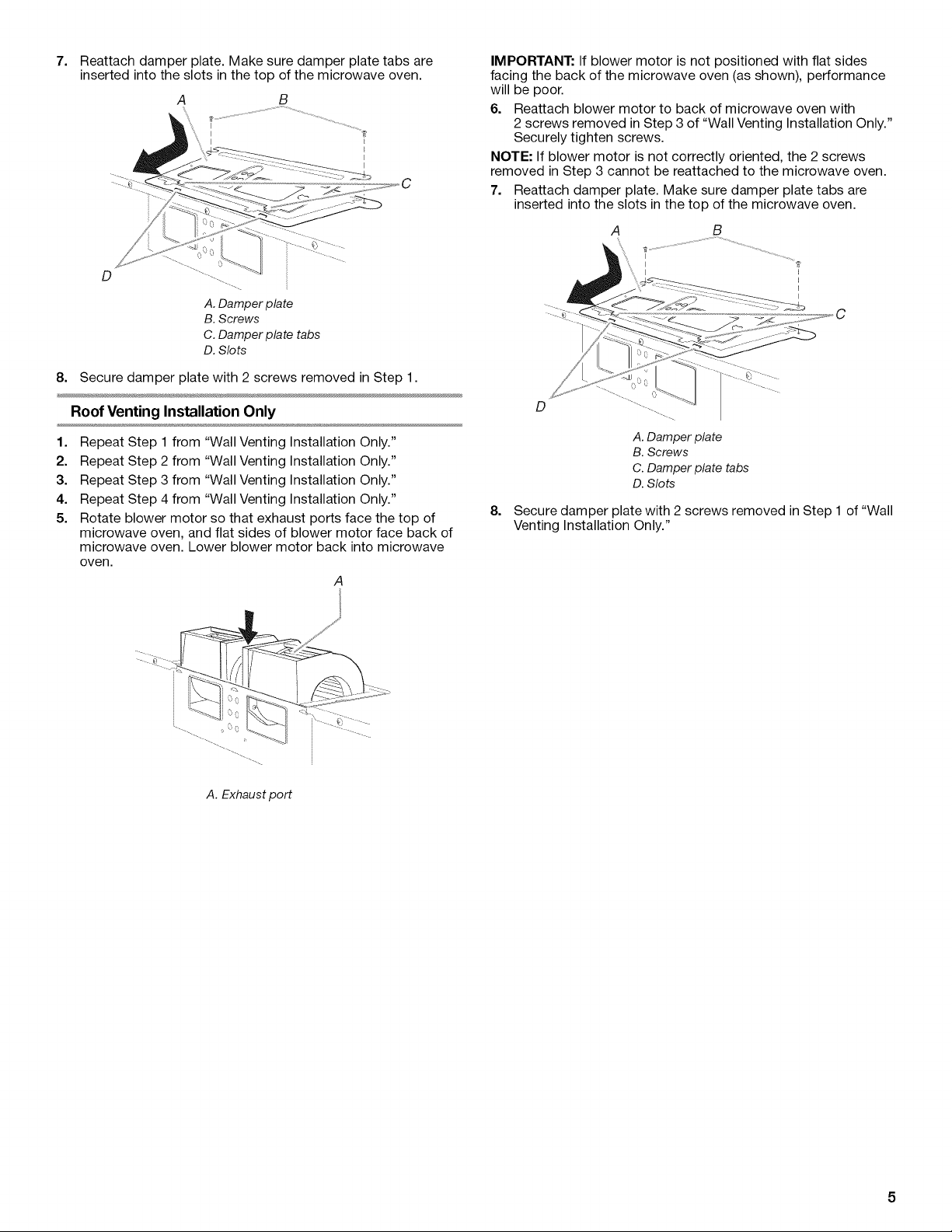
7=
Reattach damper plate. Make sure damper plate tabs are
inserted into the slots in the top of the microwave oven.
A
%
\
\l
B
D
A.Damperplate
B.Screws
C.Damperplate tabs
D.Slots
8. Securedamper plate with 2 screws removed in Step 1.
Roof Venting Installation Only
1. Repeat Step 1 from "Wall Venting Installation Only."
2. Repeat Step 2 from "Wall Venting Installation Only."
3. Repeat Step 3 from "Wall Venting Installation Only."
4. Repeat Step 4 from "Wall Venting Installation Only."
5. Rotate blower motor so that exhaust ports face the top of
microwave oven, and flat sides of blower motor face back of
microwave oven. Lower blower motor back into microwave
oven.
A
IMPORTANT: If blower motor is not positioned with flat sides
facing the back of the microwave oven (as shown), performance
will be poor.
6. Reattach blower motor to back of microwave oven with
2 screws removed in Step 3 of "Wall Venting Installation Only."
Securely tighten screws.
NOTE: If blower motor is not correctly oriented, the 2 screws
removed in Step 3 cannot be reattached to the microwave oven.
7. Reattach damper plate. Make sure damper plate tabs are
inserted into the slots in the top of the microwave oven.
A B
D
A. Damper plate
B. Screws
C. Damper plate tabs
D. Slots
8. Secure damper plate with 2 screws removed in Step 1 of "Wall
Venting Installation Only."
A. Exhaust port
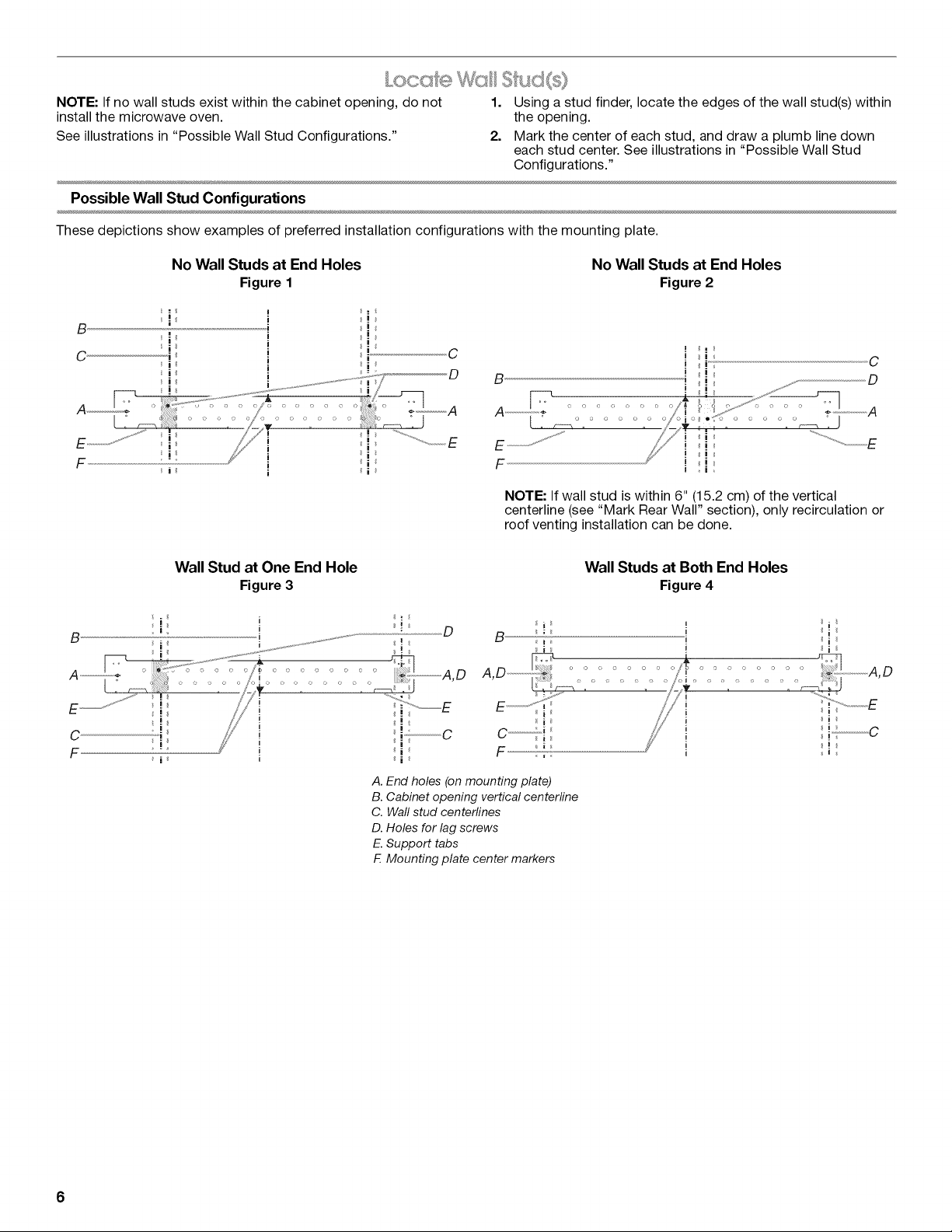
NOTE: If no wall studs exist within the cabinet opening, do not 1. Using a stud finder, locate the edges of the wall stud(s) within
install the microwave oven. the opening.
See illustrations in "Possible Wall Stud Configurations." 2. Mark the center of each stud, and draw a plumb line down
each stud center. See illustrations in "Possible Wall Stud
Configurations."
Possible Wall Stud Configurations
These depictions show examples of preferred installation configurations with the mounting plate.
B
c.................................................................:41
B
No Wall Studs at End Holes
Figure 1
I
i
i
i
i
i
i
i
Wall Stud at One End Hole
Figure3
i
i
i
i
No Wall Studs at End Holes
Figure2
C ! "
D B .] ]. D
i
NOTE: If wall stud is within 6" (15.2 cm) of the vertical
centerline (see "Mark Rear Wall" section), only recirculation or
roof venting installation can be done.
i !
i ._ C
Wall Studs at Both End Holes
Figure4
D
A,D ....................."., /! i ..............
i i i
B ; i i
I i i
" i i
..... o o/_:,........ A,D
.................... // , c
F
i
A. End holes (on mounting plate)
B. Cabinet opening vertical centerline
C. Waft stud centerlines
D. Holes for lag screws
E. Support tabs
F. Mounting plate center markers
F ..................ii--_-_ i I
6
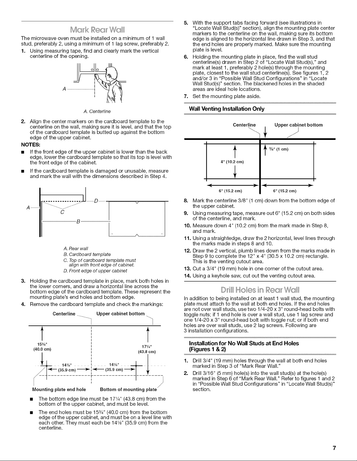
The microwave oven must be installed on a minimum of 1 wall
stud, preferably 2, using a minimum of 1 lag screw, preferably 2.
1. Using measuring tape, find and clearly mark the vertical
centerline of the opening.
A ......................}Lj__o _
5. With the support tabs facing forward (see illustrations in
"Locate Wall Stud(s)" section), align the mounting plate center
markers to the centerline on the wall, making sure its bottom
edge is aligned to the horizontal line drawn in Step 3, and that
the end holes are properly marked. Make sure the mounting
plate is level.
6. Holding the mounting plate in place, find the wall stud
centerline(s) drawn in Step 2 of "Locate Wall Stud(s)," and
mark at least 1, preferably 2 hole(s) through the mounting
plate, closest to the wall stud centerline(s). See figures 1, 2
and/or 3 in "Possible Wall Stud Configurations" in "Locate
Wall Stud(s)" section. The blackened holes in the shaded
areas are ideal hole locations.
7. Set the mounting plate aside.
A. Centerline
2. Align the center markers on the cardboard template to the
centerline on the wall, making sure it is level, and that the top
of the cardboard template is butted up against the bottom
edge of the upper cabinet.
NOTES:
• If the front edge of the upper cabinet is lower than the back
edge, lower the cardboard template so that its top is level with
the front edge of the cabinet.
• If the cardboard template is damaged or unusable, measure
and mark the wall with the dimensions described in Step 4.
A
3. Holding the cardboard template in place, mark both holes in
the lower corners, and draw a horizontal line across the
bottom edge of the cardboard template. These represent the
mounting plate's end holes and bottom edge.
4. Remove the cardboard template and check the markings:
t t
15¾" i
(40.0crn)
' i (43.8 crn)
& ' l
/" _[._(359crn)._-l_-_(35.9crn)--__,_l_. - _/_<fix.......-....................................................
Mounting plate end hole Bottom of mounting plate '//
The bottom edge line must be 171/4'' (43.8 cm) from the
bottom of the upper cabinet, and must be level.
The end holes must be 153/4'' (40.0 cm) from the bottom
edge of the upper cabinet, and must be on a level line with
each other. They must each be 141/8'' (35.9 cm) from the
centerline.
C
B
A. Rear wall
B. Cardboard template
C. Top of cardboard template must
align with front edge of cabineL
D. Front edge of upper cabinet
Centerline _ Upper cabinet bottom
i
1
t
i
141/8" i 141/a'' J-
i
171/4"
Wall Venting Installation Only
Centerline Upper cabinet bottom
f
4" (10.2 cm)
%" (1 cm)
I
=€
6" (15.2 cm)
8.
Mark the centerline 3/8" (1 cm) down from the bottom edge of
the upper cabinet.
9.
Using measuring tape, measure out 6" (15.2 cm) on both sides
of the centerline, and mark.
10.
Measure down 4" (10.2 cm) from the mark made in Step 8,
and mark.
11.
Using a straightedge, draw the 2 horizontal, level lines through
the marks made in steps 8 and 10.
12.
Draw the 2 vertical, plumb lines down from the marks made in
Step 9 to complete the 12" x 4" (30.5 x 10.2 cm) rectangle.
This is the venting cutout area.
13.
Cut a 3/4" (19 mm) hole in one corner of the cutout area.
14.
Using a keyhole saw, cut out the venting cutout area.
In addition to being installed on at least 1 wall stud, the mounting
plate must attach to the wall at both end holes. If the end holes
are not over wall studs, use two 1/4-20 x 3" round-head bolts with
toggle nuts; if 1 end hole is over a wall stud, use 1 lag screw and
one 1/4-20 x 3" round-head bolt with toggle nut; or if both end
holes are over wall studs, use 2 lag screws. Following are
3 installation configurations.
Installation for No Wall Studs at End Holes
(Figures I & 2)
1=
Drill 3/4" (19 mm) holes through the wall at both end holes
marked in Step 3 of "Mark Rear Wall."
2.
Drill 3/16" (5 mm) hole(s) into the wall stud(s) at the hole(s)
marked in Step 6 of "Mark Rear Wall." Refer to figures 1 and 2
in "Possible Wall Stud Configurations" in "Locate Wall Stud(s)"
section.
'-- <
6" (15.2 cm)
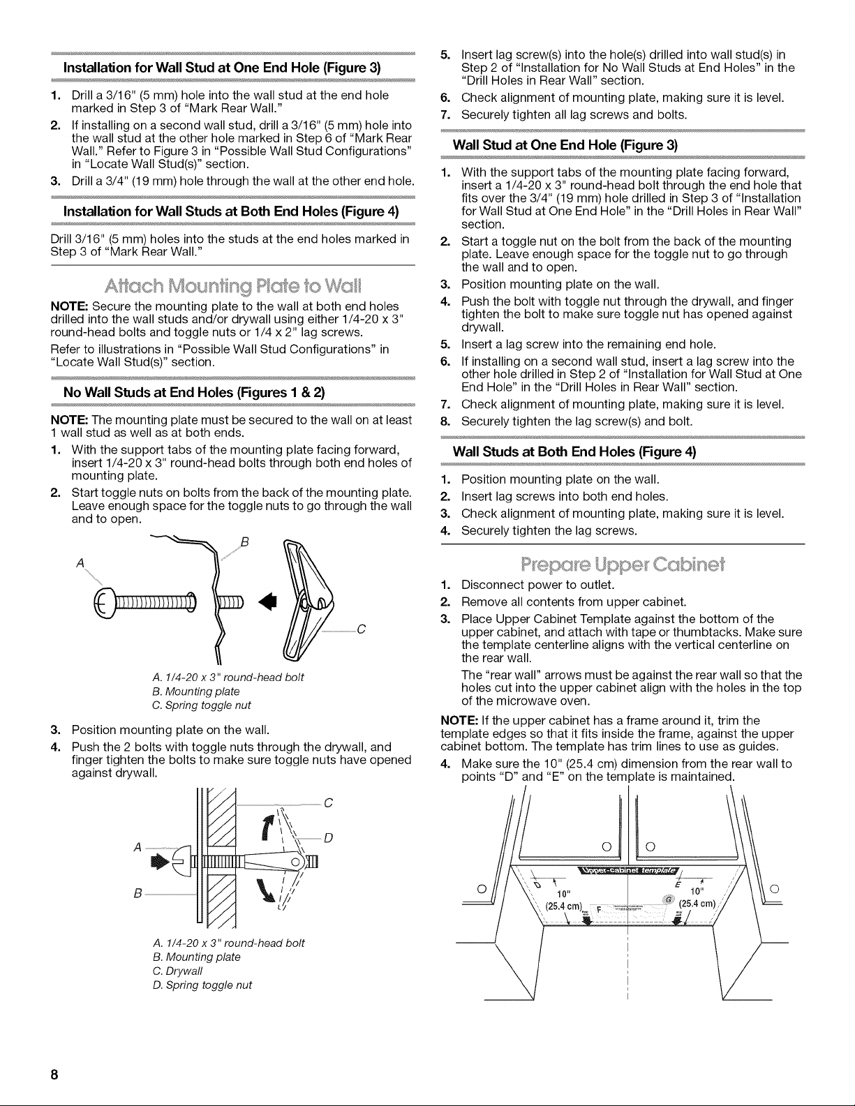
Installation for Wall Stud at One End Hole (Figure 3)
1. Drill a 3/16" (5 mm) hole into the wall stud at the end hole
marked in Step 3 of "Mark Rear Wall."
2. If installing on a second wall stud, drill a 3/16" (5 mm) hole into
the wall stud at the other hole marked in Step 6 of "Mark Rear
Wall." Refer to Figure 3 in "Possible Wall Stud Configurations"
in "Locate Wall Stud(s)" section.
3. Drill a 3/4" (19 mm) hole through the wall at the other end hole.
Installation for Wall Studs at Both End Holes (Figure 4)
Drill 3/16" (5 mm) holes into the studs at the end holes marked in
Step 3 of "Mark Rear Wall."
NOTE: Secure the mounting plate to the wall at both end holes
drilled into the wall studs and/or drywall using either 1/4-20 x 3"
round-head bolts and toggle nuts or 1/4 x 2" lag screws.
Refer to illustrations in "Possible Wall Stud Configurations" in
"Locate Wall Stud(s)" section.
No Wall Studs at End Holes (Figures I & 2)
NOTE: The mounting plate must be secured to the wall on at least
1 wall stud as well as at both ends.
1. With the support tabs of the mounting plate facing forward,
insert 1/4-20 x 3" round-head bolts through both end holes of
mounting plate.
2. Start toggle nuts on bolts from the back of the mounting plate.
Leave enough space for the toggle nuts to go through the wall
and to open.
5.
Insert lag screw(s) into the hole(s) drilled into wall stud(s) in
Step 2 of "Installation for No Wall Studs at End Holes" in the
"Drill Holes in Rear Wall" section.
6. Check alignment of mounting plate, making sure it is level.
7. Securely tighten all lag screws and bolts.
Wall Stud at One End Hole (Figure 3)
1=
With the support tabs of the mounting plate facing forward,
insert a 1/4-20 x 3" round-head bolt through the end hole that
fits over the 3/4" (19 mm) hole drilled in Step 3 of "Installation
for Wall Stud at One End Hole" in the "Drill Holes in Rear Wall"
section.
2. Start a toggle nut on the bolt from the back of the mounting
plate. Leave enough space for the toggle nut to go through
the wall and to open.
3. Position mounting plate on the wall.
4. Push the bolt with toggle nut through the drywall, and finger
tighten the bolt to make sure toggle nut has opened against
drywall.
5. Insert a lag screw into the remaining end hole.
6. If installing on a second wall stud, insert a lag screw into the
other hole drilled in Step 2 of "Installation for Wall Stud at One
End Hole" in the "Drill Holes in Rear Wall" section.
7. Check alignment of mounting plate, making sure it is level.
8. Securely tighten the lag screw(s) and bolt.
Wall Studs at Both End Holes (Figure 4)
1. Position mounting plate on the wall.
2. Insert lag screws into both end holes.
3. Check alignment of mounting plate, making sure it is level.
4. Securely tighten the lag screws.
ss,O
......S j¸s
A. 1/4-20 x 3" round-head bolt
B. Mounting plate
C. Spring toggle nut
3.
Position mounting plate on the wall.
4.
Push the 2 bolts with toggle nuts through the drywall, and
finger tighten the bolts to make sure toggle nuts have opened
against drywall.
//// ......................................................C
// / _.\\ ,-,
/-/" \
B
//
// Nj'
//
//
A. 1/4-20 x 3" round-head bolt
B. Mounting plate
C. Drywall
D. Spring toggle nut
,_ \ \\ M
1=
Disconnect power to outlet.
2.
Remove all contents from upper cabinet.
3.
Place Upper Cabinet Template against the bottom of the
upper cabinet, and attach with tape or thumbtacks. Make sure
the template centerline aligns with the vertical centerline on
the rear wall.
The "rear wall" arrows must be against the rear wall so that the
holes cut into the upper cabinet align with the holes in the top
of the microwave oven.
NOTE: If the upper cabinet has a frame around it, trim the
template edges so that it fits inside the frame, against the upper
cabinet bottom. The template has trim lines to use as guides.
4. Make sure the 10" (25.4 cm) dimension from the rear wall to
points "D" and "E" on the template is maintained.
O O
8
 Loading...