


INSTALLATION INSTRUCTIONS 24" (61.0 CM)
OR 30" (76.2 CM) BUILT-IN MICROWAVE OVEN
This product is suitable for use above electric or gas built-in ovens, and below non-vented electric or gas cooktops. This product is
not suitable for use below downdraft cooktops.
These installation instructions cover different models. The appearance of your particular model may differ slightly from the illustrations
in these Installation Instructions.
INSTRUCTIONS D’INSTALLATION DU FOUR
À MICRO-ONDES ENCASTRÉ ET ENCASTRÉS
24" (61,0 CM) OU 30" (76,2 CM)
Ce produit convient à une utilisation au-dessus de fours encastrés électriques ou à gaz, et au-dessous de tables de cuisson
électriques ou à gaz sans décharge à l’extérieur. Ce produit ne convient pas à une utilisation au-dessous de tables de cuisson avec
extraction par le bas.
Ces instructions d’installation sont valables pour plusieurs modèles. Il se peut que l’apparence de votre propre modèle soit légèrement
différente de celle illustrée dans ces Instructions d’installation.
INSTRUCCIONES DE INSTALACIÓN DE LA
COMBINACIÓN DE HORNO/MICROONDAS
EMPOTRADO ELÉCTRICO DE
24" (61,0 CM) Y 30" (76,2 CM)
Este producto puede usarse encima de hornos empotrados eléctricos o a gas y debajo de las superficies de cocción eléctricas o a
gas sin ventilación. Este producto no puede usarse debajo de superficies de cocción de tiro descendente.
Estas instrucciones de instalación abarcan modelos diferentes. La apariencia de su modelo en particular puede ser ligeramente
diferente de las imágenes en estas instrucciones de instalación.
Table of Contents/Table des matières/Índice
BUILT-IN MICROWAVE OVEN SAFETY ..2
INSTALLATION REQUIREMENTS ...........3
Tools and Parts .......................................3
Location Requirements .......................... 3
Minimum Dimensions.............................4
Product Dimensions ............................... 5
Electrical Requirements .........................6
INSTALLATION INSTRUCTIONS .............6
Install Spacer Strips ............................... 6
Install the Microwave Oven (24" [61.0
cm] Installation Only) .............................. 6
Install the Microwave Oven
(30" [76.2 cm] Installation Only) .............8
Complete Installation .............................9
ASSISTANCE ............................................9
SÉCURITÉ DU FOUR À MICRO-ONDES
ENCASTRÉ..............................................10
EXIGENCES D’INSTALLATION .............10
Outillage et composants ...................... 10
Exigences d’emplacement ...................11
Dimensions minimales .........................11
Dimensions du produit ......................... 12
Spécifications électriques .................... 12
INSTRUCTIONS D’INSTALLATION ....... 13
Installation des bandes
d’espacement ......................................13
Installation du four à micro-ondes (instal-
lation de 24" [61 cm] uniquement) ....... 13
Installation du four à micro-ondes
(Installation de 30" [76,2 cm]
uniquement) ..........................................15
Achever l’installation ............................16
ASSISTANCE ..........................................16
SEGURIDAD DEL HORNO DE
MICROONDAS INTEGRADO ................. 17
REQUISITOS DE INSTALACIÓN ........... 18
Herramientas y piezas ..........................18
Requisitos de ubicación ....................... 18
Dimensiones mínimas .......................... 19
Medidas del producto ..........................20
Requisitos eléctricos ............................ 21
INSTRUCCIONES DE INSTALACIÓN ... 21
Instalación de las tiras espaciadoras ... 21
Instale el horno microondas
(24" 61,0 cm] solo instalación). ............ 22
Instale el horno microondas
[30" (76,2 cm] solo instalación). ........... 23
Completar la instalación ......................24
AYUDA .....................................................24
IMPORTANT:
Save for local eletrical inspector’s use.
IMPORTANT :
Conserver ces instructions à l’usage de l’inspecteur des installations électriques local.
IMPORTANTE:
Guarde para tener a disposición del inspector de electricidad local.
W10909666A
BUILT-IN MICROWAVE OVEN SAFETY
Your safety and the safety of others are very important.
We have provided many important safety messages in this manual and on your appliance. Always read and obey all safety
messages.
This is the safety alert symbol.
This symbol alerts you to potential hazards that can kill or hurt you and others.
All safety messages will follow the safety alert symbol and either the word “DANGER” or “WARNING.”
These words mean:
You can be killed or seriously injured if you don't immediately
DANGER
WARNING
All safety messages will tell you what the potential hazard is, tell you how to reduce the chance of injury, and tell you what can
happen if the instructions are not followed.
follow instructions.
You
can be killed or seriously injured if you don't
instructions.
follow
2
INSTALLATION REQUIREMENTS
A
B
C
D
Tools and Parts
Tools Needed
Gather the required tools and parts before starting installation.
Read and follow the instructions provided with any tools listed
here.
■ Measuring tape
■ Pencil
■ T10 TORX
■ No. 3 square and/or No. 2 Phillips screwdriver
■ Drill
■ 5/64" (2 mm) and 7/64" (3 mm) drill bits
■ 1/4" (6 mm) shim*
* Shim may be needed for 30" (76.2 cm) installation in double-
walled cabinetry (having outer walls that protrude past the
front surface of the cutout opening). See Step 8 in the “Install
the Microwave Oven (30" [76.2 cm] Installation Only)” section.
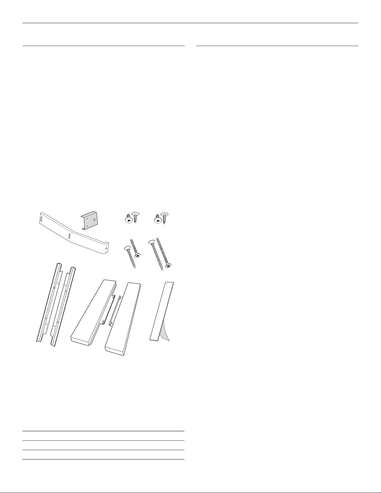
Parts Supplied
All of the following parts are provided, but not all parts will be
used. The cutout opening size will determine which parts you will
use. See chart below parts list to see which parts are used for
each installation..
®†
screwdriver
Location Requirements
The microwave oven may be located in a cabinet, and/or above
a built-in oven, or below the counter, and/or below a non-vented
cooktop. Check the opening where the microwave oven will be
installed. The location must provide:
■ Wood cabinetry.
■ Cutout opening that is plumb and square. See “Minimum
Cutout Dimensions” in the “Minimum Dimensions” section.
■ Cutout floor that is solid, level, and flush with bottom of
cabinet cutout.
■ Support for weight of at least 150 lbs (68 kg), which includes
microwave oven and items placed inside.
■ Grounded electrical outlet. See the “Electrical Requirements”
section.
■ Minimum installation clearances for installation location.
See the “Minimum Dimensions” section.
■ Complete enclosure around the recessed portion of the
microwave oven.
E
G
A. Side brackets (2)
B. Extension plates (2)
C. 3/8" (0.95 cm) T10 screws (4)
D. 1/2" (1.27 cm) T10 screws (4)
E. 1" (2.54 cm) T10 screws (4)
1
F. 1
/2" (3.81 cm) square/Phillips screws (2)
G. Mounting brackets (2)
H. Side trim panels (2)
I. Spacer strips (4)
H
F
I
INSTALLATION PARTS USED
24" (61.0 cm) installation D, E, G, I
30" (76.2 cm) installation A, B, C, E, F, H, I
†®TORX is a registered trademark of Acument Intellectual Properties, LLC
3
Minimum Dimensions
(8 mm)
(8 mm)
(25 mm)
See note
D
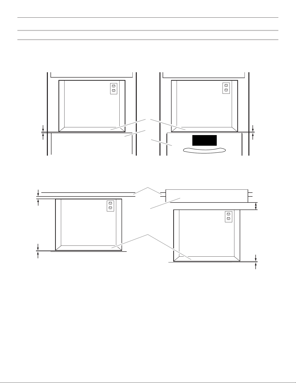
Minimum Installation Clearances
For proper installation, the following minimum clearances must exist above and below the cutout opening.
Above Cabinet/Storage Drawer Installation Above Oven/Warming Drawer Installation
A
1"
⁵⁄₁₆
"
(8 mm)
⁵⁄₁₆"
B
C
Below Counter Installation Below Built-in Cooktop Installation
E
A
⁵⁄₁₆"
(76 mm)
below.
⁵⁄₁₆
(8 mm)
3"
"
A. Cutout floor
B. Cabinet or storage drawer
NOTE: The bottom of the cooktop may be sunk into the counter and lower cabinet. The minimum 3" (7.6 cm) clearance must exist
C. Oven or warming drawer facing
(Overlaps lower opening. A minimum
distance of 3/4" [19 mm] must exist
between cutout floor [A] and lower
appliance if microwave oven is
installed over heat source.)
D. Countertop
E. Built-in cooktop (non-vented)
below the lowest point of the cooktop, and there must be no interference between any part of the cooktop (including any gas fittings)
and the microwave oven.
4
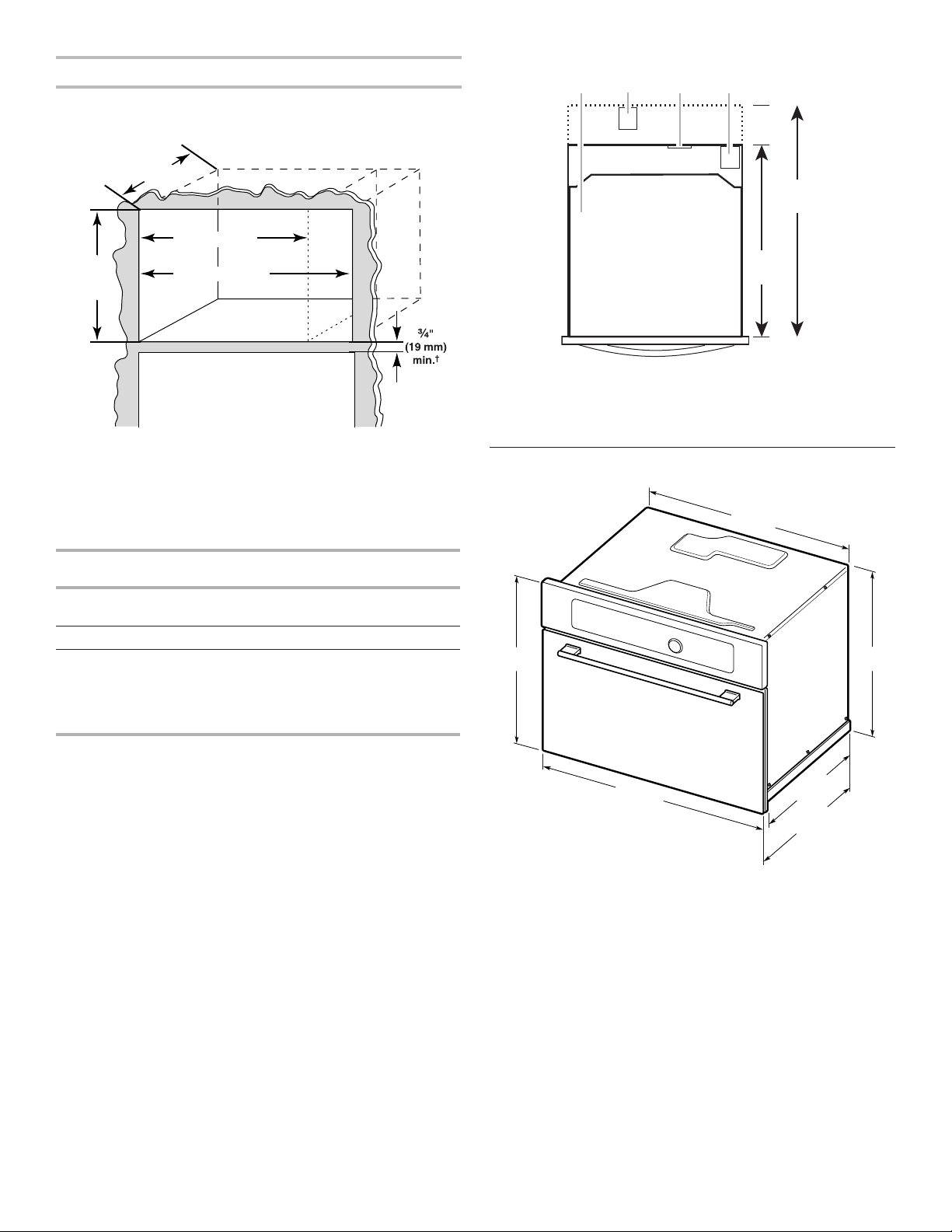
Minimum Cutout Dimensions
(45.1 cm)
(66.7 cm)
A B C D
NOTE: Depth dimension may be 213/4" (55.2 cm) with non-flush
receptacle only if the receptacle is located in upper right or
upper left corner. See “Cutout Top View.”
21
³⁄₄" (55.2 cm)*
26
¹⁄₄" (66.7 cm)**
22¹⁄₂" (57.2 cm)
17³⁄₄"
min.
* With flush receptacle, or with non-flush receptacle located in
upper right or upper left corner of cutout.
** With non-flush receptacle.
† The minimum distance of 3/4" (19 mm) must exist if microwave
oven is installed over a heat source (oven, warming drawer,
etc.).
28
¹⁵⁄₃₂" (72.3 cm)
Cutout Top View
A. Microwave oven
B. Non-flush receptacle
C. Flush receptacle
D. Non-flush receptacle located in
21³⁄₄"
(55.2 cm)
upper right or upper left corner
Product Dimensions
7
/8"
21
(55.6 cm)
26
¹⁄₄
"
DIMENSION 24" (61.0 CM)
Width 221/2" (57.2 cm)
Height Min. 173/4" (45.1 cm) for all installations
Depth 213/4" (55.2 cm) with flush receptacle,
INSTALLATION
INSTALLATION
2815/32" (72.3 cm)
30" (76.2 CM)
± 1/32" (1 mm)
± 1/16" (2 mm)
or with non-flush receptacle located in
upper right or upper left corner
261/4" (66.7 cm) with non-flush
receptacle
1
/2"
1715/16"
(45.5 cm)*
13
/32"
23
(59.5 cm)*
18
(46.4 cm)
1
21
(54 cm)*
17
(44.5 cm)
1
/4"
/4"
* Measurements include front facing of microwave oven. Depth
measurement also includes door handle.
5
Electrical Requirements
A
B
A
B
C
D
WARNING
Electrical Shock Hazard
Plug into a grounded 3 prong outlet.
Do not remove ground prong.
Do not use an adapter.
Do not use an extension cord.
Failure to follow these instructions can result in death,
fire, or electrical shock.
Observe all governing codes and ordinances.
Required:
■ A 120-volt, 60 Hz, AC-only, 15- or 20-amp electrical supply
with a fuse or circuit breaker.
Recommended:
■ A time-delay fuse or time-delay circuit breaker.
■ A separate circuit serving only this microwave oven.
GROUNDING INSTRUCTIONS
■
For all cord connected appliances:
The microwave oven must be grounded. In the event of
an electrical short circuit, grounding reduces the risk of
electric shock by providing an escape wire for the electric
current. The microwave oven is equipped with a cord
having a grounding wire with a grounding plug. The plug
must be plugged into an outlet that is properly installed
and grounded.
WARNING: Improper use of the grounding plug can
result in a risk of electric shock. Consult a qualified
electrician or serviceman if the grounding instructions are
not completely understood, or if doubt exists as to whether
the microwave oven is properly grounded.
Do not use an extension cord. If the power supply cord is
too short, have a qualified electrician or serviceman install
an outlet near the microwave oven.
SAVE THESE INSTRUCTIONS
INSTALLATION INSTRUCTIONS
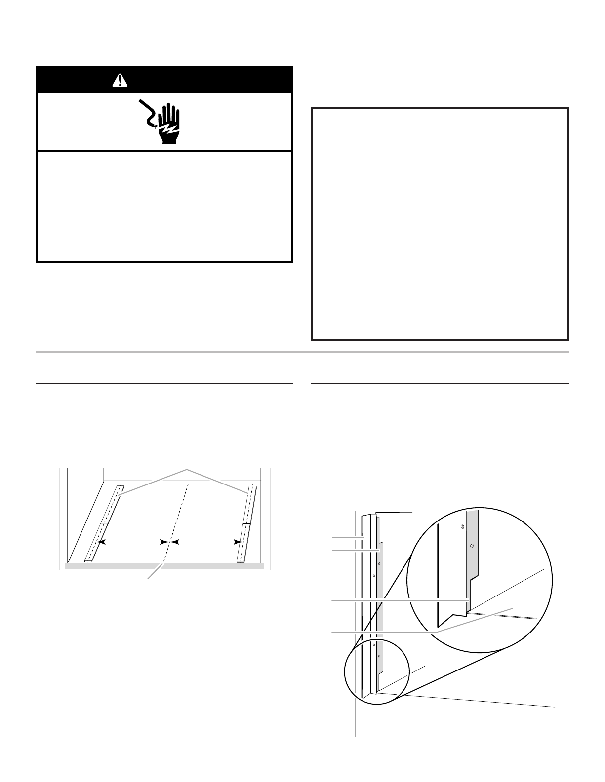
Install Spacer Strips
The provided self-adhesive spacer strips must be installed on
the cutout floor, as shown below. They are to be installed under
the feet of the microwave oven. This raises the microwave oven
1
/8" (3 mm) to ensure enough clearance for the door to open fully,
without obstruction from an installed lower appliance.
10³⁄₈" (26.4 cm) 10³⁄₈" (26.4 cm)
To Install Spacer Strips:
1. Mark centerline on floor of cutout opening.
2. Measure and mark 103/8" (26.4 cm) out on either side of
centerline.
3. Remove adhesive backing from each strip.
4. Place one spacer strip flush with the front edge of the cutout
opening. Make sure it is centered at 103/8" (26.4 cm) out from
centerline, as shown.
5. Place second spacer strip directly behind the first spacer strip.
6. Repeat on other side.
6
A. Spacer strips in place
B. Centerline
Install the Microwave Oven (24" [61.0 cm]
Installation Only)
For 24" (61.0 cm) installation, the mounting brackets must be
attached to the 2 side edges of the cutout opening.
To Attach Mounting Brackets:
1. Hold the bracket firmly against the side rim of the opening,
as shown.
The tiered edge of the bracket should be flat against the
inside wall of the opening. The small tier should rest against
the floor of the cutout opening.
A. Mounting bracket
B. Tiered edge (shaded)
C. Small tier
D. Cutout floor
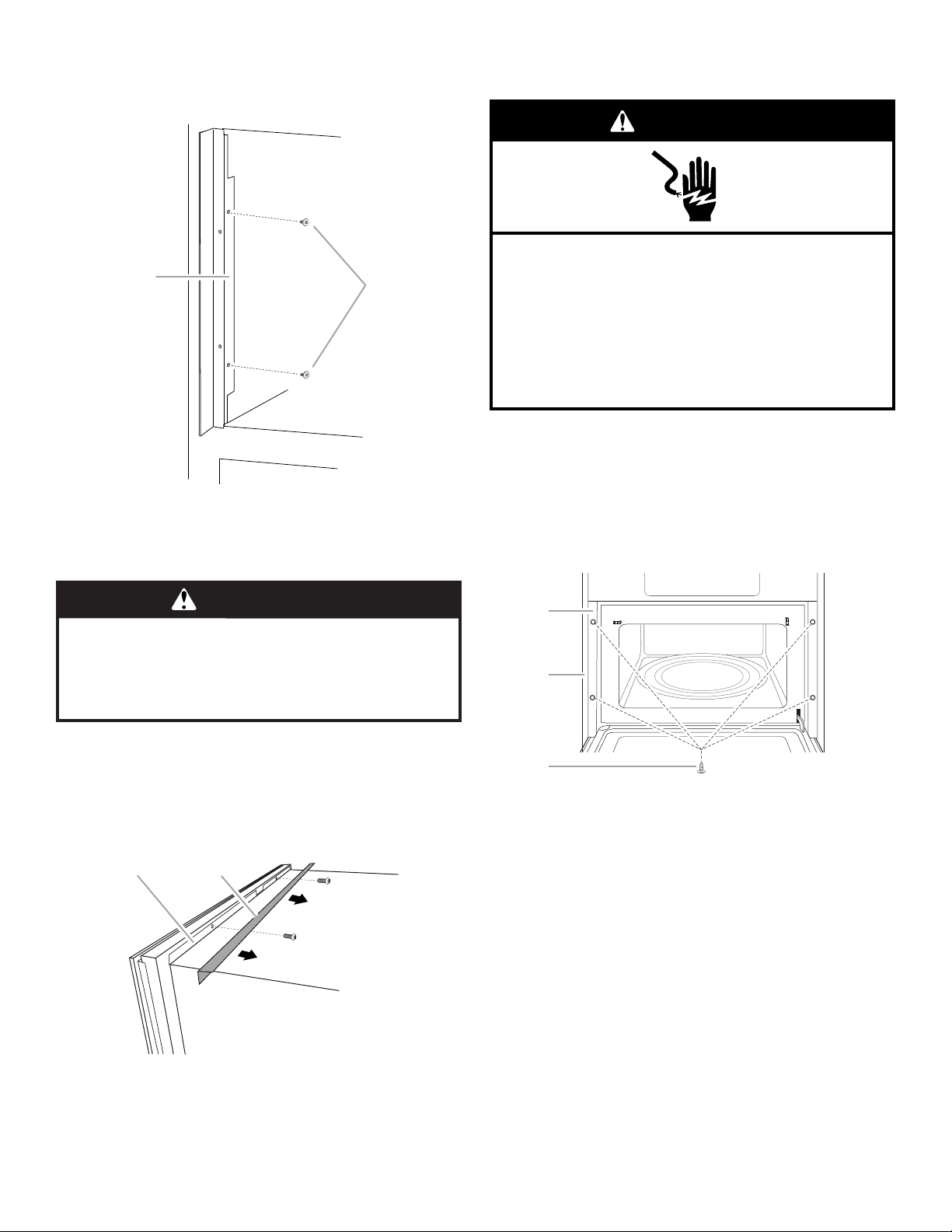
2. Using a drill with 5/64" (2 mm) bit, drill pilot holes through the
A
B
A
B
C
2 holes in the tiered edge.
3. Secure the bracket to the opening side rim with two
1/2" (1.27 cm) T10 screws.
A. Tiered edge
B. T10 screws
4. Repeat on other side.
To Install Microwave Oven:
3. Reinstall the 2 screws, securing the console to the
microwave oven.
WARNING
Electrical Shock Hazard
Plug into a grounded 3 prong outlet.
Do not remove ground prong.
Do not use an adapter.
Do not use an extension cord.
Failure to follow these instructions can result in death,
fire, or electrical shock.
4. With the microwave oven near the opening, plug the
microwave oven into the grounded 3 prong outlet.
5. Using 2 or more people, slide the microwave oven all the
way into the opening.
6. Open the microwave oven door. The holes in the door facing
frame should align with the holes in the mounting brackets.
Secure the microwave oven door facing to the mounting
brackets using four 1" (2.54 cm) T10 screws.
WARNING
Excessive Weight Hazard
Use two or more people to move and install
microwave oven.
Failure to do so can result in back or other injury.
NOTE: For this microwave oven, the door handle may be used
for lifting. Do not use any other portion of the control panel, side
brackets, front frame, or trim for lifting.
1. Empty microwave oven of any loose items.
2. From behind the console, remove the 2 screws that secure
the top complement piece to the console. The top
complement piece will not be used in this installation.
A B
7. Proceed to the “Complete Installation” section.
A. Microwave oven door
facing frame
B. Cabinet
C. 1" (2.54 cm) T10 screws (4)
A. Back of console
B. Top complement piece
7
Install the Microwave Oven
A
C
A B C
all
(30" [76.2 cm] Installation Only)
WARNING
Excessive Weight Hazard
Use two or more people to move and install
microwave oven.
Failure to do so can result in back or other injury.
1. Empty microwave oven of any loose contents.
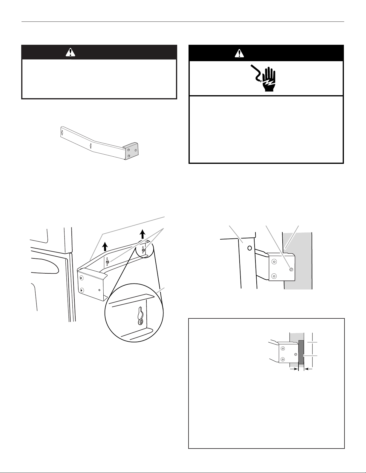
2. Attach the extension plate to each of the side brackets using
3/8" (0.95 cm) T10 screws, as shown.
3. Loosen the middle and rear screws on each side of
microwave oven. The screws are located at the same height
as the door handle.
4. Place the side bracket over the 2 screws, fitting the screw
heads through the keyholes on the bracket. Then slide the
side bracket up so that the lower portions of the keyholes
rest on the screws.
B
WARNING
Electrical Shock Hazard
Plug into a grounded 3 prong outlet.
Do not remove ground prong.
Do not use an adapter.
Do not use an extension cord.
Failure to follow these instructions can result in death,
fire, or electrical shock.
7. With the microwave oven near the opening, plug the
microwave oven into the grounded 3 prong outlet.
8. Using 2 or more people, slide microwave oven all the way
into the opening, and center the microwave oven within the
opening.
NOTE: The screw holes in the winged ends of both side
brackets must be fully over the wood of the wall or cabinet,
as shown.
A. Side bracket
B. Existing screws (middle and rear)
C. Proper side bracket attachment
5. Tighten screws to secure the side bracket to the microwave
oven.
6. Repeat steps 4 and 5 on the other side of the microwave
oven.
8
A. Door front facing
B. Side bracket screw hole
for cabinet attachment
C. Cabinet front
For installation in double-walled cabinetry only:
The clearance of 1/4" (6 mm)
must exist between the end of
the side bracket and the outer
wall.
If this clearance exists,
proceed to Step 9 below, and
complete installation.
If this clearance does not
exist, follow these steps:
a. Wedge 1/4" (6 mm) shim between side bracket and outer
wall;
b. Use 7/64" (3 mm) drill to drill pilot hole through screw hole
in side bracket;
c. Install 11/2" (3.81 cm) square/Phillips screw, and then
remove shim.
d. Repeat steps a, b, and c on other side.
NOTE: To ensure proper side trim panel fitting, do not
overtighten screws.
Proceed to Step 11.
¹⁄₄" (6 mm)
Outer w
Shim
 Loading...