

Ikea IHW7302YS1, IHW7302YS0 Owner’s Manual

DATID
30" (76.2 CM) WALL-MOUNT CANOPY
RANGE HOOD
Installation Instructions and Use & Care Guide
For questions about features, operation/performance, parts, accessories or service, call: 1-866-664-2449.
In Canada, for assistance, installation and service, call: 1-866-664-2449.
CAMPANA PARA COCINA CON ESCUDETE DE
MONTAJE EN LA PARED, DE 30" (76,2 CM)
Instrucciones de instalación y Manual de uso y cuidado
Si tiene preguntas respecto a las características, funcionamiento, rendimiento, partes, accesorios o servicio técnico, llame al:
1-866-664-2449.
HOTTE DE CUISINIÈRE À MONTAGE MURAL DE
30" (76,2 CM)
Instructions d’installation et Guide d’utilisation et d’entretien
Au Canada, pour assistance, installation ou service, composez le 1-866-664-2449.
Table of Contents/Índice/Table des matières..................................................................2
For warranty concerns, do not take the appliance back to the store. Please contact us in U.S.A. or Canada at 1-866-664-2449.
This product features a Limited Warranty - See the “Warranty” section for complete details. IKEA® appliances carry a 5-year
warranty (excludes LAGAN family - see warranty for coverage details).
NOTE: Proof of Purchase is required to obtain warranty service.
Si tiene dudas acerca de la garantía, no devuelva el aparato a la tienda. Póngase en contacto con nosotros en los EE.UU. o en
Canadá al 1-866-664-2449.
Este producto tiene una garantía limitada - Consulte la sección “Garantía” para obtener todos los detalles. Los aparatos IKEA®
tienen una garantía de 5 años (excluyendo los de la familia LAGAN - consulte la garantía para ver los detalles acerca de la
cobertura).
NOTA: Se requiere la prueba de compra para obtener servicio bajo la garantía.
Pour toute question concernant l’application de la garantie, ne pas rapporter l’appareil au magasin. Veuillez nous contacter aux
É.-U. ou au Canada au 1-866-664-2449.
Ce produit est couvert par une garantie limitée – Voir la section “Garantie” pour des détails complets. Les appareils IKEA® sont
couverts par une garantie de 5 ans (hormis les appareils de la série LAGAN - voir la garantie pour des détails concernant les
modalités de garantie).
REMARQUE : Une preuve d’achat est obligatoire pour obtenir l'application de la garantie.
IMPORTANT: READ AND SAVE THESE INSTRUCTIONS.
FOR RESIDENTIAL USE ONLY.
IMPORTANTE: LEA Y GUARDE ESTAS INSTRUCCIONES.
SÓLO PARA USO RESIDENCIAL.
IMPORTANT : LIRE ET CONSERVER CES INSTRUCTIONS.
POUR UTILISATION RÉSIDENTIELLE UNIQUEMENT.
LI3ZYD/W10392947D

TABLE OF CONTENTS
RANGE HOOD SAFETY ........................................................... 3
INSTALLATION REQUIREMENTS .......................................... 5
Tools and Parts .................................................................... 5
Location Requirements ....................................................... 5
Venting Requirements ......................................................... 6
Electrical Requirements ....................................................... 7
INSTALLATION INSTRUCTIONS ........................................... 8
Prepare Location ................................................................. 8
Install Range Hood ............................................................... 9
Connect Vent System ........................................................... 9
Make Electrical Connection ............................................... 10
Install Vent Covers ............................................................. 10
Complete Installation ......................................................... 11
ÍNDICE
SEGURIDAD DE LA CAMPANA PARA COCINA .................. 17
REQUISITOS DE INSTALACIÓN .......................................... 19
Herramientas y piezas ....................................................... 19
Requisitos de ubicación .................................................... 19
Requisitos de ventilación .................................................. 20
Requisitos eléctricos ......................................................... 21
INSTRUCCIONES DE INSTALACIÓN ................................. 22
Preparación de la ubicación .............................................. 22
Instalación de la campana para cocina ............................. 23
Conexión del sistema de ventilación .................................. 23
Conexión del suministro eléctrico ..................................... 24
Instalación de las cubiertas del ducto de escape ............. 25
Complete la instalación ..................................................... 25
RANGE HOOD USE ............................................................... 11
Range Hood Controls ........................................................ 11
RANGE HOOD CARE ........................................................... 12
Cleaning ............................................................................ 12
WIRING DIAGRAM ............................................................... 13
ASSISTANCE OR SERVICE ................................................. 14
In the U.S.A. ...................................................................... 14
In Canada .......................................................................... 14
Accessories ....................................................................... 14
WARRANTY .......................................................................... 15
USO DE LA CAMPANA PARA COCINA ................................ 25
Controles de la campana para cocina ............................... 25
CUIDADO DE LA CAMPANA PARA COCINA ..................... 26
Limpieza ............................................................................ 26
DIAGRAMA DE CABLEADO ................................................ 27
AYUDA O SERVICIO TÉCNICO ........................................... 28
En los EE.UU. .................................................................... 28
Accesorios ......................................................................... 28
GARANTÍA ............................................................................ 29
TABLE DES MATIÈRES
SÉCURITÉ DE LA HOTTE DE CUISINIÈRE .......................... 31
EXIGENCES D'INSTALLATION ............................................ 33
Outils et pièces .................................................................. 33
Exigences d’emplacement ................................................ 33
Exigences concernant l’évacuation ................................... 34
Spécifications électriques ................................................. 35
INSTRUCTIONS D'INSTALLATION ..................................... 36
Préparation de l'emplacement ........................................... 36
Installation de la hotte ....................................................... 37
Raccordement du circuit d'évacuation .............................. 37
Raccordement électrique .................................................. 38
Installation des cache-conduits ........................................ 39
Achever l’installation ......................................................... 39
UTILISATION DE LA HOTTE ................................................. 39
Commandes de la hotte de cuisinière ............................... 39
ENTRETIEN DE LA HOTTE ................................................. 40
Nettoyage .......................................................................... 40
SCHÉMA DE CÂBLAGE ....................................................... 41
ASSISTANCE OU SERVICE ................................................. 42
Au Canada ......................................................................... 42
Accessoires ........................................................................ 42
GARANTIE ............................................................................ 43
2

RANGE HOOD SAFETY
Your safety and the safety of others are very important.
We have provided many important safety messages in this manual and on your appliance. Always read and obey all safety
messages.
This is the safety alert symbol.
This symbol alerts you to potential hazards that can kill or hurt you and others.
All safety messages will follow the safety alert symbol and either the word “DANGER” or “WARNING.”
These words mean:
You can be killed or seriously injured if you don't immediately
DANGER
WARNING
All safety messages will tell you what the potential hazard is, tell you how to reduce the chance of injury, and tell you what can
happen if the instructions are not followed.
follow instructions.
You
can be killed or seriously injured if you don't
instructions.
follow
3

IMPORTANT SAFETY INSTRUCTIONS
READ AND SAVE THESE INSTRUCTIONS
State of California Proposition 65 Warnings:
WARNING: This product contains one or more chemicals known to the State of California to cause cancer.
WARNING: This product contains one or more chemicals known to the State of California to cause birth defects or other
reproductive harm.
4
INSTALLATION REQUIREMENTS
Tools and Parts
Gather the required tools and parts before starting installation.
Read and follow the instructions provided with any tools
listed here.
Tools needed
■ Level
■ Drill with 1¼" (3.0 cm), ³⁄
■ Pencil
■ Wire stripper or utility knife
■ Tape measure or ruler
■ Pliers
■ Caulking gun and weatherproof caulking compound
■ Vent clamps
■ Jigsaw or keyhole saw
■ Flat-blade screwdriver
■ Metal snips
■ Phillips screwdriver
■ Metric hex key set
Parts needed
■ Home power supply cable
■ ½" (12.7 mm) UL listed or CSA approved strain relief
■ 3 UL listed wire connectors
For vented installations, you will also need:
■ 1 wall or roof cap
■ Metal vent system
For non-vented (recirculating) installations, you will also need:
■ Charcoal Filter Kit Part Number W10412939 for non-vented
(recirculating) installations only. See “Assistance or Service”
section to order.
■ 6" (15.2 cm) dia. round metal vent duct - length required is
determined by ceiling height.
8" (9.5 mm), and ³⁄16" (4.8 mm) drill bits
■ 2 - Flat washers
■ 4 - 4.2 x 8 mm screws
Location Requirements
IMPORTANT: Observe all governing codes and ordinances.
Have a qualified technician install the range hood. It is the
installer's responsibility to comply with installation clearances
specified on the model/serial rating plate. The model/serial
rating plate is located behind the filter on the rear wall of the
vent hood.
Canopy hood location should be away from strong draft areas,
such as windows, doors and strong heating vents.
Cabinet opening dimensions that are shown must be used.
Given dimensions provide minimum clearance.
Grounded electrical outlet is required. See “Electrical
Requirements” section.
The canopy hood is factory set for venting through the roof
or wall. For non-vented (recirculating) Installation see “For
Non-vented (recirculating) Installation Only” in “Connect Vent
System” section. Charcoal Filter Kit Part Number W10412939 is
available from your dealer or an authorized parts distributor.
All openings in ceiling and wall where canopy hood will be
installed must be sealed.
For Mobile Home Installations
The installation of this range hood must conform to the
Manufactured Home Construction Safety Standards, Title
24 CFR, Part 328 (formerly the Federal Standard for Mobile
Home Construction and Safety, Title 24, HUD, Part 280)
or when such standard is not applicable, the standard for
Manufactured Home Installation 1982 (Manufactured Home
Sites, Communities and Setups) ANSI A225.1/NFPA 501A, or
latest edition, or with local codes.
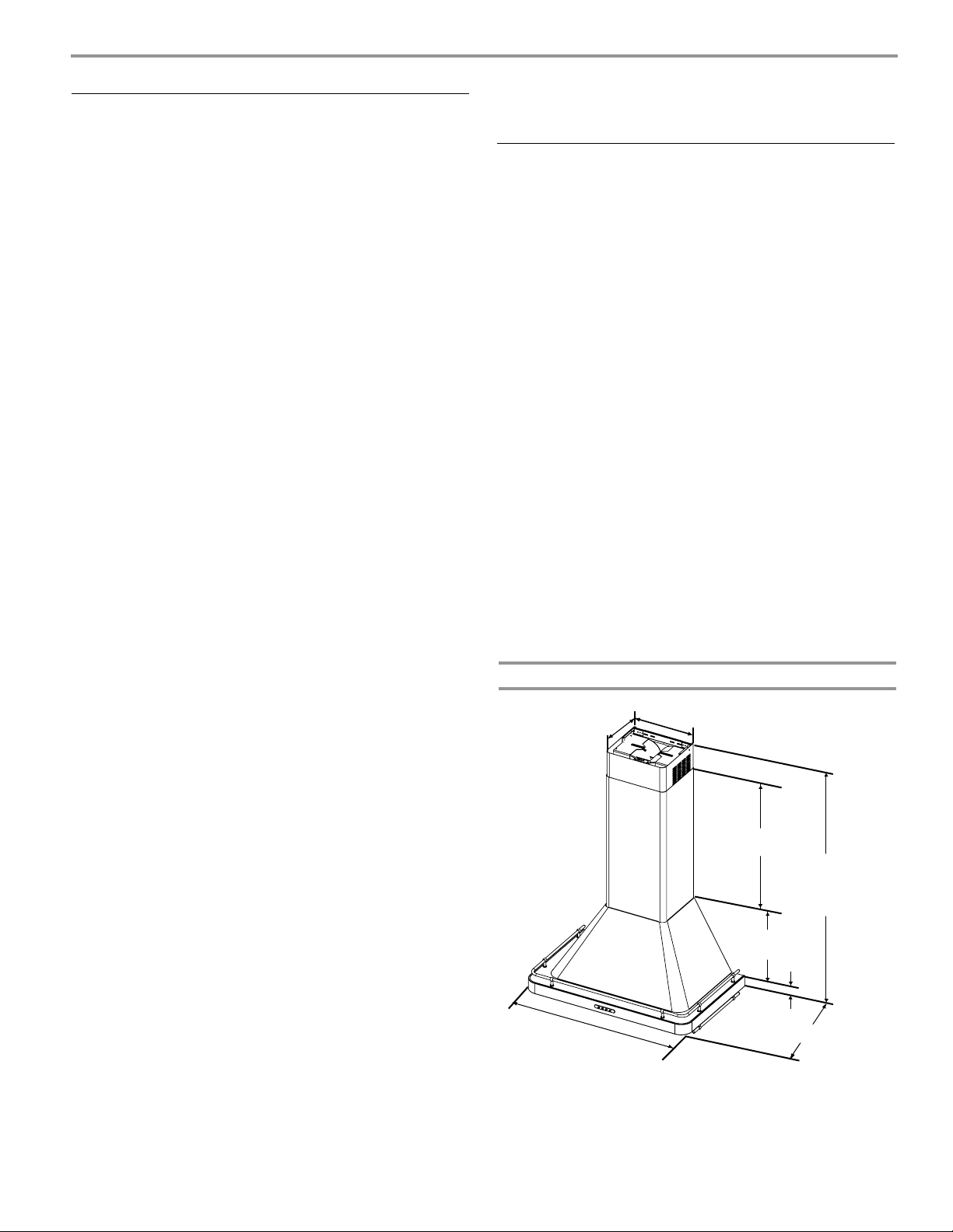
Product Dimensions
9³⁄₈"
(23.8 cm)
10⁷⁄₈"
(27.6 cm)
Parts supplied
Remove parts from packages. Check that all parts are included.
■ Hood canopy assembly with ventilator and light bulbs installed
■ Vent transition with back draft dampers installed
■ Metal grease filter(s)
■ Vent cover support bracket
■ Mounting template
■ Air deflector with extensions (for non-vented installations)
■ 2-piece vent cover
■ 6 - 3.5 x 6.5 mm screws
■ 2 - 2.9 x 6.5 mm screws
■ 6 - 5 x 45 mm mounting screws
■ 6 - 8 x 40 mm wall anchors
®†
■ T10 Torx
■ T20
†®TORX and T20 are registered trademarks of Acument Intellectual Properties, LLC.
adapter
®
Torx®† adapter
(35.5 cm)
(34.9 cm)
2" (5.1 cm)
30" (76.2 cm)
*For non-vented (recirculating) installations
**For vented installations
14"
*32³⁄₈" (82.2 cm) min.
**31³⁄₈" (79.7 cm) min.
*44³⁄₄" (113.7 cm) max.
**41" (104.1 cm) max.
13³⁄₄"
18⁷⁄₈" (48.0 cm)
5

Cabinet Dimensions
7¹⁄₄" (18.4 cm)
6⁵⁄₈" (16.8 cm)
7³⁄₈" (18.7 cm)
Side
cabinet
30" (76.2 cm)
“X”
bottom of
canopy
to cooking
surface
*For non-vented (recirculating) installations
IMPORTANT:
Minimum distance “X”: 24" (61.0 cm) from electric cooking
surface.
Minimum distance “X”: 27" (68.6 cm) from gas cooking
surfaces.
Suggested maximum distance “X”: 36" (91.4 cm)
The chimneys can be adjusted for different ceiling heights. See
the following chart.
2" (5.1 cm) min.
6" (15.2 cm) min.*
15" (38.1 cm)
Centerline
Cooking surface
Vent and power
supply cable
entry location
Side
cabinet
Vented Installations
Min. ceiling height Max. ceiling height
Electric cooking
7' 7" (2.31 m) 9' 5" (2.87 m)
surface
Gas cooking
7' 11" (2.41 m) 9' 5" (2.87 m)
surface
Non-vented (recirculating) Installations
Min. ceiling height Max. ceiling height
Electric cooking
surface
Gas cooking
surface
*NOTE: The range hood chimneys are adjustable and designed
to meet varying ceiling or soffit heights depending on the
distance “X” between the bottom of the range hood and the
cooking surface.
7' 8" (2.34 m) 9' 8" (2.95 m)
7' 11" (2.41 m) 9' 8" (2.95 m)
Venting Requirements
(vented models only)
■ Vent system must terminate to the outdoors except for
non-vented (recirculating) installations.
■ Do not terminate the vent system in an attic or other
enclosed area.
■ Do not use 4" (10.2 cm) laundry-type wall cap.
■ Use metal vent only. Rigid metal vent is recommended.
Plastic or metal foil vent is not recommended.
■ The length of vent system and number of elbows should be
kept to a minimum to provide efficient performance.
For the most efficient and quiet operation:
■ Use no more than three 90° elbows.
■ Make sure there is a minimum of 24" (61 cm) of straight
vent between the elbows if more than 1 elbow is used.
■ Do not install 2 elbows together.
■ Use clamps to seal all joints in the vent system.
■ The vent system must have a damper. If the roof or wall
cap has a damper, do not use the damper supplied with the
range hood.
■ Use caulking to seal exterior wall or roof opening around
the cap.
■ The size of the vent should be uniform.
Cold Weather Installations
An additional back draft damper should be installed to minimize
backward cold air flow and a thermal break should be installed
to minimize conduction of outside temperatures as part of the
vent system. The damper should be on the cold air side of the
thermal break.
The break should be as close as possible to where the vent
system enters the heated portion of the house.
Makeup Air
Local building codes may require the use of makeup air
systems when using ventilation systems greater than specified
CFM of air movement. The specified CFM varies from
locale to locale. Consult your HVAC professional for specific
requirements in your area.
Venting Methods
This canopy hood is factory set for venting through the roof or
wall.
A 6" (15.2 cm) round vent system is needed for installation (not
included). The hood exhaust opening is 6" (15.2 cm) round.
NOTE: Flexible vent is not recommended. Flexible vent
creates back pressure and air turbulence that greatly reduce
performance.
Vent system can terminate either through the roof or wall. To
vent through a wall, a 90° elbow is needed.
Rear discharge
A 90° elbow may be installed immediately above the hood.
6
 Loading...