

Page 1

30" (76.2 CM) ISLAND-MOUNT CANOPY
IMPORTANT: READ AND SAVE THESE INSTRUCTIONS.
FOR RESIDENTIAL USE ONLY.
IMPORTANTE: LEA Y GUARDE ESTAS INSTRUCCIONES.
SÓLO PARA USO RESIDENCIAL.
IMPORTANT : LIRE ET CONSERVER CES INSTRUCTIONS.
POUR UTILISATION RÉSIDENTIELLE UNIQUEMENT.
LI302G/W10502581H
RANGE HOOD
Installation Instructions and Use & Care Guide
For questions about features, operation/performance, parts, accessories or service, call: 1-866-664-2449.
In Canada, for assistance, installation and service, call: 1-866-664-2449.
CAMPANA DE COCINA PARA ISLA CON ESCUDETE
DE 30" (76,2 CM)
Instrucciones de instalación y Manual de uso y cuidado
Si tiene preguntas respecto a las características, funcionamiento, rendimiento, partes, accesorios o servicio técnico, llame al: 1-866-664-2449.
HOTTE DE CUISINIÈRE CONFIGURÉE EN ÎLOT
30" (76,2 CM)
Instructions d’installation et Guide d’utilisation et d’entretien
Au Canada, pour assistance, installation ou service, composez le 1-866-664-2449
Table of Contents/Índice/Table des matières..................................................................2
For warranty concerns, do not take the appliance back to the store. Please contact us in U.S.A. or Canada at 1-866-664-2449.
This product features a Limited Warranty - See the “Warranty” section for complete details. IKEA
(excludes LAGAN family - see warranty for coverage details).
NOTE: Proof of Purchase is required to obtain warranty service.
Si tiene dudas acerca de la garantía, no devuelva el aparato a la tienda. Póngase en contacto con nosotros en los EE.UU. o en Canadá
al 1-866-664-2449.
Este producto tiene una garantía limitada - Consulte la sección “Garantía” para obtener todos los detalles. Los aparatos IKEA
una garantía de 5 años (excluyendo los de la familia LAGAN - consulte la garantía para ver los detalles acerca de la cobertura).
NOTA: Se requiere la prueba de compra para obtener servicio bajo la garantía.
Pour toute question concernant l’application de la garantie, ne pas rapporter l’appareil au magasin. Veuillez nous contacter aux É.-U.
ou au Canada au 1-866-664-2449.
Ce produit est couvert par une garantie limitée – Voir la section “Garantie” pour des détails complets. Les appareils IKEA
par une garantie de 5 ans (hormis les appareils de la série LAGAN - voir la garantie pour des détails concernant les modalités de
garantie).
REMARQUE : Une preuve d’achat est obligatoire pour obtenir l'application de la garantie.
®
appliances carry a 5-year warranty
®
tienen
®
sont couverts
Page 2

TABLE OF CONTENTS
RANGE HOOD SAFETY .................................................................3
INSTALLATION REQUIREMENTS................................................5
Tools and Parts ............................................................................5
Location Requirements................................................................5
Venting Requirements..................................................................6
Electrical Requirements ...............................................................7
INSTALLATION INSTRUCTIONS..................................................8
Prepare Location..........................................................................8
Assemble Range Hood ................................................................9
Install Range Hood.......................................................................9
Make Electrical Connection .......................................................10
Install Duct Covers.....................................................................11
ÍNDICE
SEGURIDAD DE LA CAMPANA PARA COCINA .......................19
REQUISITOS DE INSTALACIÓN.................................................21
Herramientas y piezas................................................................21
Requisitos de ubicación.............................................................21
Requisitos de ventilación ...........................................................22
Requisitos eléctricos..................................................................23
INSTRUCCIONES DE INSTALACIÓN.........................................24
Prepare la ubicación ..................................................................24
Ensamble la campana para cocina............................................25
Instalación de la campana para cocina.....................................26
Haga la conexión del suministro eléctrico.................................26
Instale las cubiertas del conducto.............................................27
Complete Installation..................................................................12
RANGE HOOD USE......................................................................13
Range Hood Controls.................................................................13
RANGE HOOD CARE ...................................................................14
Cleaning......................................................................................14
WIRING DIAGRAM ......................................................................15
ASSISTANCE OR SERVICE.........................................................16
In the U.S.A. ...............................................................................16
In Canada ...................................................................................16
Accessories ................................................................................16
WARRANTY ..................................................................................17
Complete la instalación..............................................................29
USO DE LA CAMPANA PARA COCINA .....................................29
Controles de la campana para cocina.......................................29
CUIDADO DE LA CAMPANA PARA COCINA............................30
Limpieza .....................................................................................30
DIAGRAMA DE CABLEADO .......................................................31
AYUDA O SERVICIO TÉCNICO...................................................32
En los EE.UU. .............................................................................32
Accesorios..................................................................................32
GARANTÍA.....................................................................................33
TABLE DES MATIÈRES
SÉCURITÉ DE LA HOTTE DE CUISINIÈRE ...............................35
EXIGENCES D'INSTALLATION...................................................37
Outils et pièces...........................................................................37
Exigences d’emplacement.........................................................37
Exigences concernant l'évacuation...........................................38
Spécifications électriques..........................................................39
INSTRUCTIONS D’INSTALLATION ............................................40
Préparation de l'emplacement...................................................40
Assemblage de la hotte .............................................................41
Installation de la hotte................................................................42
Raccordement électrique...........................................................42
Installation des cache-conduits.................................................43
Achever l’installation ..................................................................45
UTILISATION DE LA HOTTE .......................................................45
Commandes de la hotte de cuisinière .......................................45
ENTRETIEN DE LA HOTTE..........................................................46
Nettoyage ...................................................................................46
SCHÉMA DE CÂBLAGE...............................................................47
ASSISTANCE OU SERVICE.........................................................48
Au Canada..................................................................................48
Accessoires ................................................................................48
GARANTIE.....................................................................................49
2
Page 3

RANGE HOOD SAFETY
You can be killed or seriously injured if you don't immediately
You
can be killed or seriously injured if you don't
follow
All safety messages will tell you what the potential hazard is, tell you how to reduce the chance of injury, and tell you what can
happen if the instructions are not followed.
Your safety and the safety of others are very important.
We have provided many important safety messages in this manual and on your appliance. Always read and obey all safety
messages.
This is the safety alert symbol.
This symbol alerts you to potential hazards that can kill or hurt you and others.
All safety messages will follow the safety alert symbol and either the word “DANGER” or “WARNING.”
These words mean:
follow instructions.
instructions.
DANGER
WARNING
State of California Proposition 65 Warnings:
WARNING: This product contains one or more chemicals known to the State of California to cause cancer.
WARNING: This product contains one or more chemicals known to the State of California to cause birth defects or other
reproductive harm.
3
Page 4

IMPORTANT SAFETY INSTRUCTIONS
READ AND SAVE THESE INSTRUCTIONS
WARNING: TO REDUCE THE RISK OF FIRE, ELECTRIC
SHOCK, OR INJURY TO PERSONS, OBSERVE THE
FOLLOWING:
■ Use this unit only in the manner intended by the
manufacturer. If you have questions, contact the
manufacturer.
■ Before servicing or cleaning the unit, switch power off at
service panel and lock the service disconnecting means to
prevent power from being switched on accidentally. When
the service disconnecting means cannot be locked,
securely fasten a prominent warning device, such as a tag,
to the service panel.
■ Installation work and electrical wiring must be done by
qualified person(s) in accordance with all applicable codes
and standards, including fire-rated construction.
■ Do not operate any fan with a damaged cord or plug.
Discard fan or return to an authorized service facility for
examination and/or repair.
■ Sufficient air is needed for proper combustion and
exhausting of gases through the flue (chimney) of fuel
burning equipment to prevent backdrafting. Follow the
heating equipment manufacturer's guideline and safety
standards such as those published by the National Fire
Protection Association (NFPA), the American Society for
Heating, Refrigeration and Air Conditioning Engineers
(ASHRAE), and the local code
authorities.
■ When cutting or drilling into wall or ceiling; do not damage
electrical wiring and other hidden utilities.
■ Ducted fans must always be vented outdoors.
CAUTION: For general ventilating use only. Do not use
to exhaust hazardous or explosive materials and vapors.
CAUTION: To reduce risk of fire and to properly exhaust
air, be sure to duct air outside - do not vent exhaust air into
spaces within walls or ceilings, attics or into crawl spaces,
or garages.
WARNING: TO REDUCE THE RISK OF FIRE, USE ONLY
METAL DUCTWORK.
WARNING: TO REDUCE THE RISK OF A RANGE TOP
GREASE FIRE:
■ Never leave surface units unattended at high settings.
Boilovers cause smoking and greasy spillovers that may
ignite. Heat oils slowly on low or medium settings.
■ Always turn hood ON when cooking at high heat or when
flambeing food (i.e. Crepes Suzette, Cherries Jubilee,
Peppercorn Beef Flambé).
■ Clean ventilating fans frequently. Grease should not be
allowed to accumulate on fan or filter.
■ Use proper pan size. Always use cookware appropriate for
the size of the surface element.
WARNING: TO REDUCE THE RISK OF INJURY TO
PERSONS IN THE EVENT OF A RANGE TOP GREASE
FIRE, OBSERVE THE FOLLOWING:
a
■ SMOTHER FLAMES with a close fitting lid, cookie sheet, or
metal tray, then turn off the burner. BE CAREFUL TO
PREVENT BURNS. If the flames do not go out
immediately, EVACUATE AND CALL THE FIRE
DEPARTMENT.
■ NEVER PICK UP A FLAMING PAN - you may be burned.
■ DO NOT USE WATER, including wet dishcloths or towels -
a violent steam explosion will result.
■ Use an extinguisher ONLY if:
– You know you have a class ABC extinguisher, and you
already know how to operate it.
– The fire is small and contained in the area where it
started.
– The fire department is being called.
– You can fight the fire with your back to an exit.
a
Based on "Kitchen Fire Safety Tips" published by NFPA.
■ WARNING: To reduce the risk of fire or electrical shock,
do not use this fan with any solid-state speed control
device.
4
Page 5

INSTALLATION REQUIREMENTS
†®TORX and T20 are registered trademarks of Acument Intellectual Properties, LLC.
Tools and Parts
Gather the required tools and parts before starting installation.
Read and follow the instructions provided with any tools listed
here.
Tools needed
■ Level
■ Drill with 1¼" (3.0 cm), ³⁄₈" (9.5 mm), ⁷⁄₆₄" (2.75 mm) and
¹⁄₈" (3.0 mm) drill bits
■ Pilot hole drill bits (determined by chimney support
attachment method)
■ Pencil
■ Wire stripper or utility knife
■ Tape measure or ruler
■ Pliers
■ Caulking gun and weatherproof caulking compound
■ Vent clamps
■ Jigsaw or keyhole saw
■ Flat-blade screwdriver
■ Metal snips
■ Phillips screwdriver
Parts needed
■ Home power supply cable
■ ½" (12.7 mm) UL listed or CSA approved strain relief
■ 3 UL listed wire connectors
For vented installations, you will also need:
■ 1 wall or roof cap
■ Metal vent system
For non-vented (recirculating) installations, you will also
need:
■ Charcoal Filter Kit Part Number W10412939 for non-vented
(recirculating) installations only. See “Assistance or Service”
section to order.
■ 6" (15.2 cm) round metal vent duct. Length required is
determined by ceiling height.
Parts supplied
Remove parts from packages. Check that all parts are included.
■ Hood ventilator assembly with canopy glass, retainer
brackets, rubber seals, and light bulb installed.
■ Metal grease filter
■ 4 - 5 x 45 mm screws (#2 Phillips drive)
■ T10 Torx
■ T20
■ 62 - 4.2 x 8 mm screws (T20
■ 4 - 3.5 x 6.5 mm screws (T10 drive)
■ 2 - 2.9 x 3 mm screws (T10 drive)
■ 4 - Vent covers
■ 4 - Plastic vent clips
®†
adapter)
®
Tor x® adapter
®
drive
■ Mounting template
■ Upper horizontal support bracket
■ Horizontal support
■ 8 - Vertical supports
■ 2 - Vent cover supports
■ Air deflector (for non-vented/recirculating installations)
■ Vent transition with back draft damper installed
■ 2 - 3.5 x 9.5 mm mounting screws (T10 drive)
Location Requirements
IMPORTANT: Observe all governing codes and ordinances.
Have a qualified technician install the range hood. It is the
installer's responsibility to comply with installation clearances
specified on the model/serial rating plate. The model/serial rating
plate is located behind the left filter on the rear wall of the vent
hood.
Canopy hood location should be away from strong draft areas,
such as windows, doors and strong heating vents.
Cabinet opening dimensions that are shown must be used. Given
dimensions provide minimum clearance.
Grounded electrical outlet is required. See “Electrical
Requirements” section.
Because of the size and weight of this island hood, the chimney
support must be securely attached to the ceiling.
■ For plaster or drywall ceilings, the chimney support must be
attached to joists. If this is not possible, you must build a
support structure behind the plaster or drywall. The support
structure must be able to support 80 lbs (36.6 kg).
This range hood is recommended for use with cooktops with a
maximum total rating of 60,000 BTUs or less.
The range hood is factory set for venting through the roof or wall.
For non-vented (recirculating) installation see “Non-vented
(recirculating) Installation” in “Install Range Hood” section.
Charcoal Filter Kit Part Number W10412939 is available from
your dealer or an authorized parts distributor.
All openings in ceiling and wall where range hood will be installed
must be sealed.
For Mobile Home Installations
The installation of this range hood must conform to the
Manufactured Home Construction Safety Standards, Title 24
CFR, Part 328 (formerly the Federal Standard for Mobile Home
Construction and Safety, Title 24, HUD, Part 280) or when such
standard is not applicable, the standard for Manufactured Home
Installation 1982 (Manufactured Home Sites, Communities and
Setups) ANSI A225.1/NFPA 501A, or latest edition, or with local
codes.
5
Page 6

Product Dimensions
A
B
C
D
E
F
A
B
D
C
A. 12¼" (31.1 cm)
B. 13
³⁄₁₆
" (33.5 cm)
C. *29
³⁄₄
" (75.6 cm) min. 44
**29
³⁄₄
F. 2 5
¹⁄₂
" (8.9 cm)
³⁄₁₆
" (64.0 cm)
" (75.6 cm) min. 49
D. 3
E. 30" (76.2 cm)
*Vented installations only
**Non-vented (recirculating) installations only
Installation Dimensions
A. Countertop height
B. Hood height from ceiling to bottom of the range
hood filter surface: D-A-C=B
C. Hood height: 24" (61.0 cm) min. from electric
cooking surface, 27" (68.6 cm) min. from gas
cooking surface, suggested 36" (91.4 cm) max.
D. Ceiling height
IMPORTANT:
Minimum distance “C”: 24" (61.0 cm) from electric cooking
surface, 27" (68.6 cm) from gas cooking surface
Suggested maximum distance “C”: 36" (91.4 cm)
¹³⁄₁₆
" (113.8 cm) max.
¹³⁄₁₆
" (126.5 cm) max.
The chimneys can be adjusted for different ceiling heights. See
the following chart.
Vented Installations
Min. ceiling height Max. ceiling height
Electric cooking
7' 8" (2.34 m) 9' 10" (3.0 m)
surface
Gas cooking
7' 11" (2.41 m) 9' 10" (3.0 m)
surface
Non-vented (recirculating) Installations
Min. ceiling height Max. ceiling height
Electric cooking
7' 8" (2.34 m) 10' 3" (3.12 m)
surface
Gas cooking
7' 11" (2.41 m) 10' 3" (3.12 m)
surface
*NOTE: The range hood chimneys are adjustable and designed
to meet varying ceiling or soffit heights depending on the
distance “C” between the bottom of the range hood and the
cooking surface. For higher ceilings, a Stainless Steel Chimney
Extension Kit Part Number W10272078 is available from your
dealer or an authorized parts distributor. The chimney extension
replaces the chimney shipped with the range hood.
Venting Requirements
■ Vent system must terminate to the outside, except for non-
vented (recirculating) installations.
■ Do not terminate the vent system in an attic or other enclosed
area.
■ Do not use 4" (10.2 cm) laundry-type wall caps.
■ Use metal vent only. Rigid metal vent is recommended. Do
not use plastic or metal foil vent.
■ The vent system must have a damper. If the roof or wall cap
has a damper, do not use the damper supplied with the range
hood.
For the most efficient and quiet operation:
■ Use a straight run or as few elbows as possible.
■ Use no more than three 90° elbows.
■ Make sure there is a minimum of 24" (61.0 cm) of straight
vent between the elbows if more than 1 elbow is used.
■ Do not install 2 elbows together.
■ Use vent clamps to seal all joints in the vent system.
■ Use caulking to seal exterior wall or roof opening around the
cap.
■ The size of the vent should be uniform.
Cold Weather Installations
An additional back draft damper should be installed to minimize
backward cold air flow and a thermal break should be installed to
minimize conduction of outside temperatures as part of the vent
system. The damper should be on the cold air side of the thermal
break.
The break should be as close as possible to where the vent
system enters the heated portion of the house.
Makeup Air
Local building codes may require the use of makeup air systems
when using ventilation systems greater than specified CFM of air
movement. The specified CFM varies from locale to locale.
Consult your HVAC professional for specific requirements in your
area.
6
Page 7
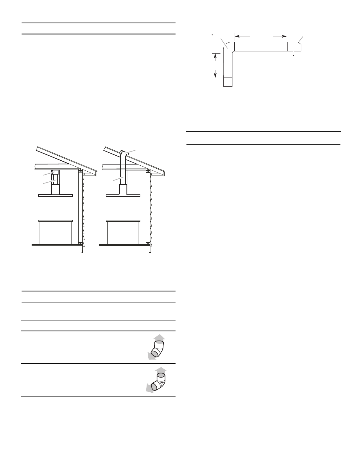
Venting Methods
B
A
B
A
90 elbow
6 ft (1.8 m)
2 ft
(0.6 m)
Wall cap
This island hood is factory set for venting through the roof.
A 6" (15.2 cm) round vent system is needed for installation (not
included). The hood exhaust opening is 6" (15.2 cm) round.
NOTE: Flexible vent is not recommended. Flexible vent creates
back pressure and air turbulence that greatly reduce
performance.
Vent system can terminate either through the roof or wall. To vent
through a wall, a 90° elbow is needed.
For Non-Vented (recirculating) Installations
If it is not possible to vent cooking fumes and vapors to the
outside, the hood can be used in the non-vented (recirculating)
version, fitting a charcoal filter and the deflector. Fumes and
vapors are recycled through the top of the grille. To order, see the
“Assistance or Service” section.
Non-vented (recirculating) Roof Venting
A. Deflector
B. 6" (15.2 cm) round vent
A. Roof cap
B. 6" (15.2 cm) round vent
NOTE: If codes permits, wall venting can be an option for 2-story
homes.
Calculating Vent System Length
To calculate the length of the system you need, add the
equivalent feet (meters) for each vent piece used in the system.
Vent piece 6" (15.2 cm) round
45° elbow 2.5 ft
(0.8 m)
90° elbow 5.0 ft
(1.5 m)
Maximum equivalent vent length is 35 ft (10.7 m).
Example Vent System
The following example falls within the maximum vent length of
35 ft (10.7 m).
1 - 90° elbow = 5.0 ft (1.5 m)
1 - wall cap = 0.0 ft (0.0 m)
8 ft (2.4 m) straight = 8.0 ft (2.4 m)
System length = 13 ft (3.9 m)
Electrical Requirements
Observe all governing codes and ordinances.
Ensure that the electrical installation is adequate and in
conformance with National Electrical Code, ANSI/NFPA 70 (latest
edition), or CSA Standards C22.1-94, Canadian Electrical Code,
Part 1 and C22.2 No. 0-M91 (latest edition) and all local codes
and ordinances.
If codes permit and a separate ground wire is used, it is
recommended that a qualified electrician determine that the
ground path is adequate.
A copy of the above code standards can be obtained from:
National Fire Protection Association
1 Batterymarch Park
Quincy, MA 02169-7471
CSA International
8501 East Pleasant Valley Road
Cleveland, OH 44131-5575
■ A 120 volt, 60 Hz., AC only, 15-amp, fused electrical circuit is
required.
■ If the house has aluminum wiring, follow the procedure
below:
1. Connect a section of solid copper wire to the pigtail
leads.
2. Connect the aluminum wiring to the added section of
copper wire using special connectors and/or tools
designed and UL listed for joining copper to aluminum.
Follow the electrical connector manufacturer's recommended
procedure. Aluminum/copper connection must conform with
local codes and industry accepted wiring practices.
■ Wire sizes and connections must conform with the rating of
the appliance as specified on the model/serial rating plate.
The model/serial plate is located behind the filter on the rear
wall of the range hood.
■ Wire sizes must conform to the requirements of the National
Electrical Code, ANSI/NFPA 70 (latest edition), or CSA
Standards C22. 1-94, Canadian Electrical Code, Part 1 and
C22.2 No. 0-M91 (latest edition) and all local codes and
ordinances.
7
Page 8
INSTALLATION INSTRUCTIONS
WARNING
Excessive Weight Hazard
Use two or more people to move and install
range hood.
Failure to do so can result in back or other injury.
A
B
C
A
B
Prepare Location
■ Lay out the vent duct system before installing the range hood
to determine the best routing for the vent duct.
■ It is recommended that the vent system be installed before
the range hood is installed.
■ Before making cutouts, make sure there is proper clearance
within the ceiling for exhaust vent.
■ Range hood is to be installed 24" (61.0 cm) min. for electric
cooking surfaces, 27" (68.6 cm) min. for gas cooking
surfaces, to a suggested maximum of 36" (91.4 cm) above
the cooking surface.
■ Remove film from metal surfaces as needed prior to
assembly.
■ Check your ceiling height and the range hood height
maximum before you install your hood.
1. Disconnect power.
2. Determine which venting method to use: roof, wall or non-
vented.
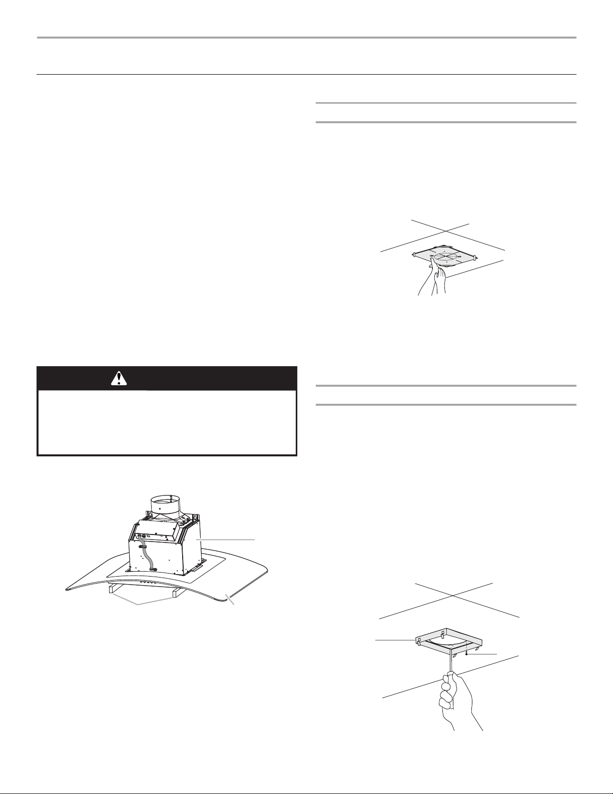
3. Select a flat surface for assembling the range hood. Place
covering over that surface. Place two 3" (7.6 cm) high
spacers (not included) onto the covered surface.
NOTE: Cover the spacers to avoid damage to the range hood
surface.
Range Hood Mounting Screws Installation
1. Determine and mark the centerline on the ceiling where the
range hood will be installed, considering the requirements for
ceiling support structures. See the “Location Requirements”
section. Make sure the range hood is centered over the
cooking surface.
2. Tape template in place on the ceiling at the marked
centerline. The line for the front of the range hood should be
parallel to the front of the cooktop.
3. Use a pencil to mark the mounting screws, wire access and
duct hole locations on the ceiling.
NOTE: Mounting hole locations should be into a ceiling
support structure capable of holding 80 lbs (36.6 kg).
Remove the template.
4. Drill 4 - ³⁄₁₆" (4.8 mm) pilot holes for mounting the upper
horizontal support.
4. Using 2 or more people, lift range hood onto covered
spacers.
A. Covered spacers
B. Glass canopy
C. Ventilator assembly
Complete Preparation
1. Determine the required location for the home power supply
cable and drill a ½" (1.3 cm) diameter hole for wire access.
2. Run ½" (1.3 cm) conduit and wires or home power supply
cable according to the National Electrical Code or CSA
Standards and local codes and ordinances. There must be
enough ½" conduit and wires or home power supply cable
from the fused disconnect (or circuit breaker) box to make the
connection in the hood’s electrical terminal box.
NOTE: Do not reconnect power until installation is complete.
3. For vented installations only: Using a jigsaw or keyhole
saw, cut a 6½" (16.5 cm) diameter hole for the vent duct.
4. Attach the upper horizontal support bracket with 4 - 5 x
45 mm #2 Phillips wood screws.
NOTE: Upper horizontal support screws must be into a
ceiling support structure capable of holding 80 lbs (36.6 kg).
8
A. Upper horizontal support
B. 5 x 45 mm screws (#2 Phillips drive)
Page 9
Assemble Range Hood
B
A
B
A
A
C
C
A
B
C
C
C
C
D
B
A
A
B
B
A
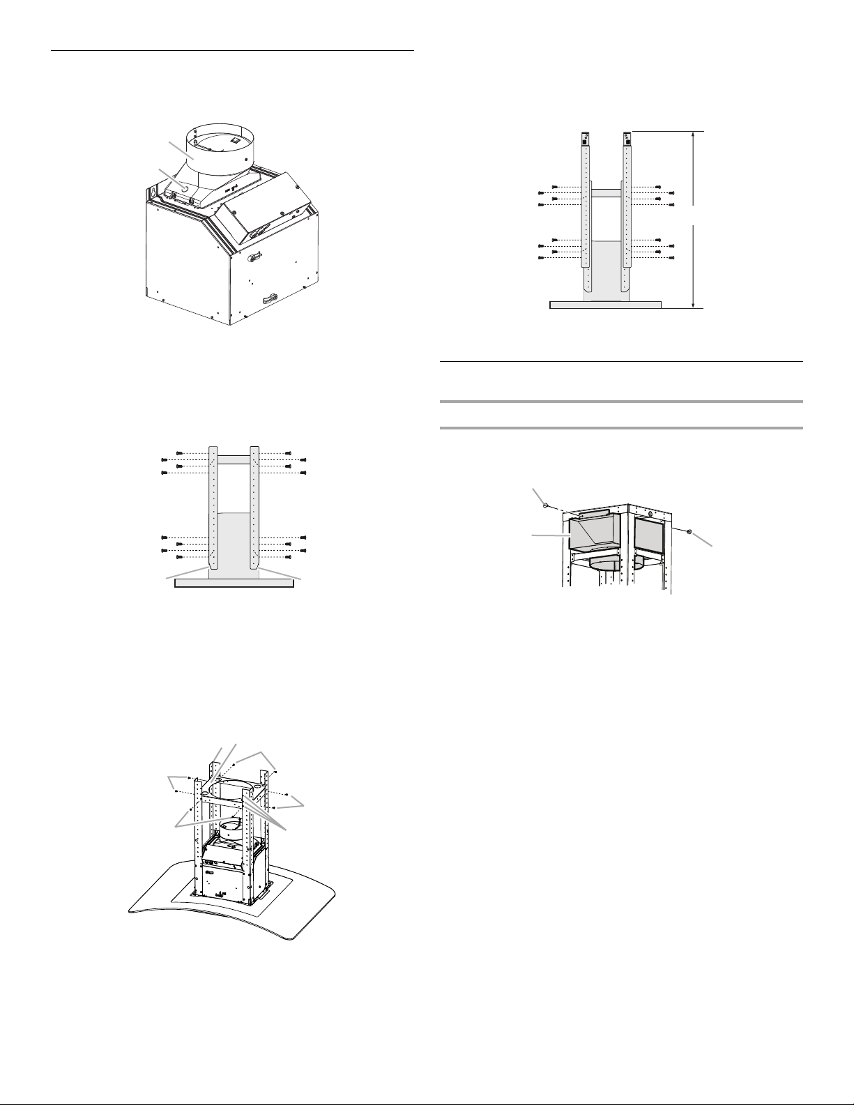
1. Install transition on top of hood (if removed for shipping) with
2 - 3.5 x 9.5 mm T10 drive sheet metal screws.
A. Vent transition
B. 3.5 x 9.5 mm screw
4. Attach a second set of vertical supports (A) and set the
vertical height (B). See “Installation Dimensions” in the
“Location Requirements” section to help determine the
desired dimension for vertical height “B.”
Secure with 16 - 4.2 x 8 mm T20
A. Vertical supports
B. Vertical height
®
screws.
2. Position the 4 vertical supports (A) with the notches at the
bottom and attach to the range hood using 16 - 4.2 x 8 mm
®
T20
screws. Use a T20® Tor x® drive (or T20® adapter
provided) to tighten all assembly screws.
A. Vertical supports
B. Horizontal support
C. Notched end
3. Position the lower horizontal support (B) as shown (flanges
pointed down). Attach to the lower vertical supports using 8 -
4.2 x 8 mm T20® screws. The lower horizontal support can be
positioned at any of the three mounting hole locations in the
lower vertical supports.
Install Range Hood
Non-Vented (recirculating) Installation
1. Attach the air deflector to the upper horizontal support using
2 - 4.2 x 8 mm T20
A. Deflector
B. 2 - 4.2 x 8 mm T20
2. Measure the length of 6" (15.2 cm) duct needed to connect
the transition to the deflector.
NOTE: Vent should fit up inside the deflector 1" (2.5 cm)
minimum.
3. Install vent between the transition and the deflector.
NOTE: To make vent installation easier, temporarily remove
the deflector from the chimney support bracket and replace
after vent section is in place.
4. Seal all connections with vent clamps. Continue with “Range
Hood Installation” in this section.
®
mounting screws.
®
mounting screws
A. Vertical supports (4)
B. Horizontal support
C. Screws 4.2 x 8 mm T20
D. Mounting hole locations for horizontal support
®
(8)
9
Page 10
Range Hood Installation
A
WARNING
Electrical Shock Hazard
Disconnect power before servicing.
Replace all parts and panels before operating.
Failure to do so can result in death or electrical shock.
C
B
A
A
B
C
D
E
F
G
WARNING
Electrical Shock Hazard
Electrically ground blower.
Connect ground wire to green and yellow ground wire
in terminal box.
Failure to do so can result in death or electrical shock.
1.
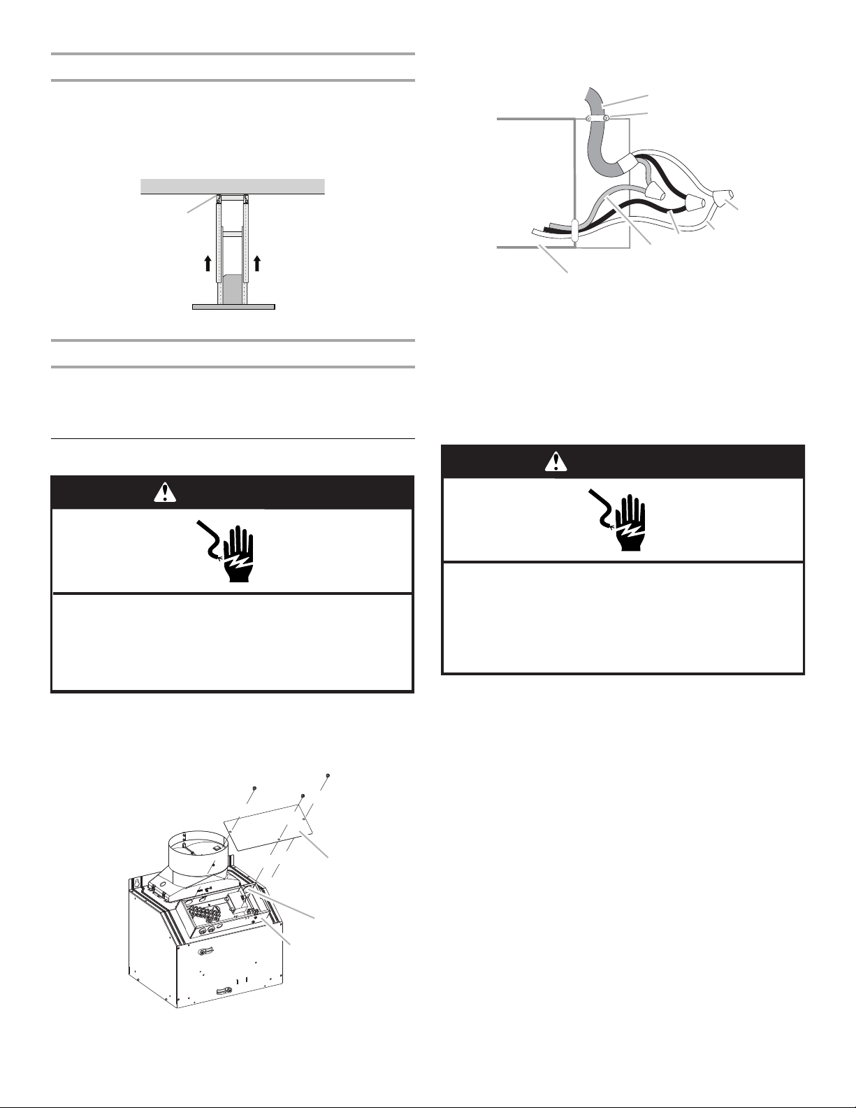
Using 2 or more people, lift the range hood assembly and attach
it by snapping the vertical supports to the spring clips in the
upper horizontal support bracket that is mounted to the ceiling.
NOTE: The range hood assembly must be held in place while
installing the screws in the next step.
2. Install 16 - 4.2 x 8 mm T20
®
screws, and tighten to secure.
4. Run home power supply cable through strain relief, into
terminal box.
A. Mounting screws
Connect Vent System
1. Install vent system.
2. Push duct over the exhaust outlet. Seal all connections with
vent clamps.
3. Use caulk to seal all openings.
Make Electrical Connection
1. Disconnect power.
2. Remove terminal box cover using a T10 Torx
adapter provided) to remove the screws.
3. Remove the knockout in the terminal box and install a UL
listed or CSA approved ¹⁄₂" strain relief.
®
drive (or T10
A. Home power supply cable
B. UL listed or CSA approved
strain relief
C. UL listed wire connectors
D. White wires
5. Use UL listed wire connectors and connect black wires (E)
together.
6. Use UL listed wire connectors and connect white wires (D)
together.
7. Connect green (or bare) ground wire from home power supply
to yellow-green ground wire (F) in terminal box using UL listed
wire connectors.
8. Tighten strain relief screw.
9. Install terminal box cover.
10. Check that all light bulbs are secure in their sockets.
11. Reconnect power.
E. Black wires
F. Green (or bare) and yellow-
green ground wires
G. Terminal box
10
A. Knockout
B. Terminal box
C. Terminal box cover
Page 11
Install Duct Covers
A
A
B
C
C
A
B
C
B
C
A
D
B
A
A
B
D
C
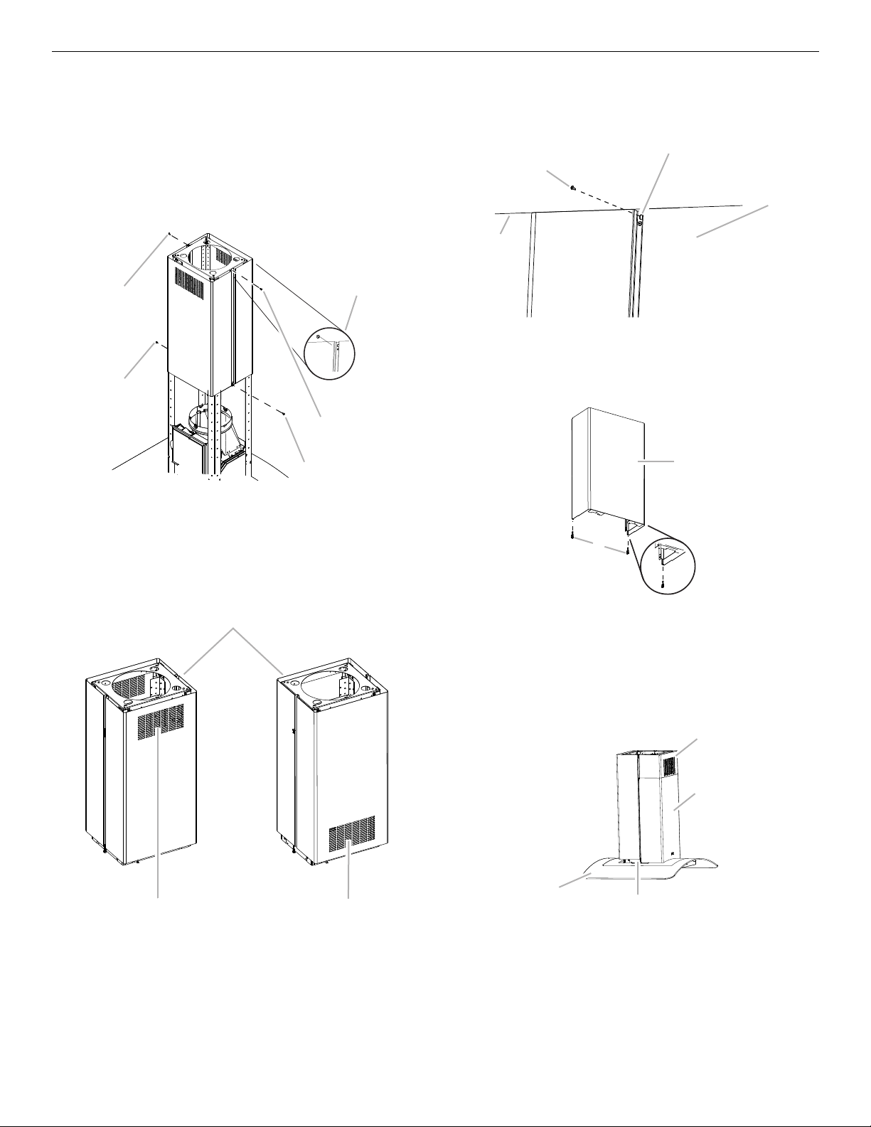
NOTE: Remove the film from the duct covers.
1. Assemble the upper duct covers together and install the duct
covers around the support frame. The larger hole in the
flanges of the upper duct cover must be outside the smaller
hole in the mating flange of the other upper duct cover.
2. Secure the upper duct covers together with two 3.5 x 6.5 mm
screws at the top and two 2.9 x 3 mm screws at the bottom.
Install 1 screw on each side at the top and bottom of the
assembled duct covers.
3. Slide the upper duct covers up the frame to the ceiling and
secure to the upper horizontal support with 2 - 3.5 x 6.5 mm
screws.
A. 3.5 x 6.5 mm screws (2)
B. Assembly holes (larger hole outside of
smaller hole on both sides)
C. 2.9 x 3 mm screws (2)
NOTE: For non-vented (recirculating) installation, the slotted
holes in the upper duct covers will be visible when assembled.
For vented installations, the slotted holes will be hidden down
inside the lower duct covers.
A. 3.5 x 6.5 mm screw
B. Slotted holes (2)
C. Upper duct covers
D. Ceiling
4. Place the long end of the plastic clips (2) into the bottom of
the front lower duct cover.
A. Lower duct cover - (front)
B. Plastic clips (2) (long end for front placement)
5. Install the lower duct cover (front) to the range hood canopy.
Spread the lower duct cover opening slightly and position it
over the upper duct cover. Set the lower duct cover in place.
Position so the flanges of the lower duct cover set into the
flanges of the upper duct covers.
A. Top toward ceiling
B. Slots installed up for non-vented installations
C. Slots installed down for vented installations
A. Range hood canopy
B. Plastic clips
C. Lower duct covers
D. Upper duct covers
11
Page 12
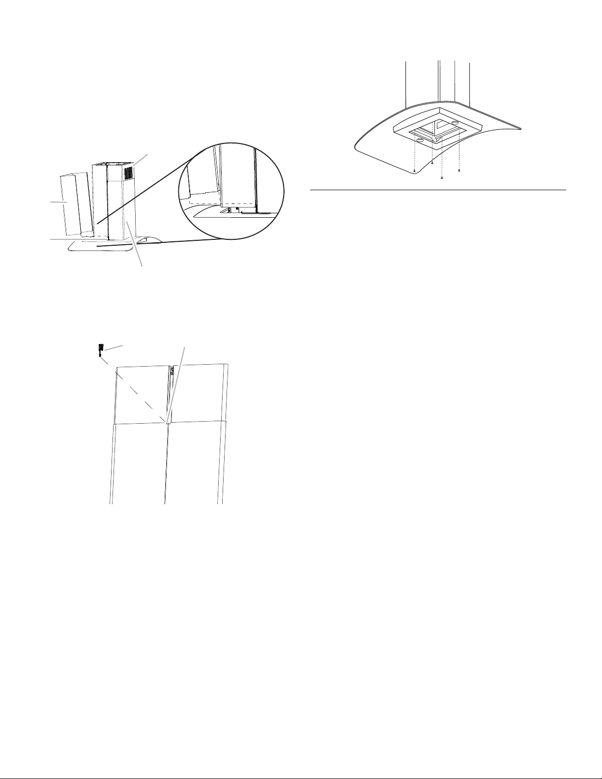
6. Install the lower duct cover (rear) to the range hood canopy.
A
B
D
C
A
B
Spread the lower duct cover opening slightly and position it
over the upper duct cover. Set the lower duct cover in place.
Position so the flanges of the lower duct cover set into the
flanges of the upper duct cover. Make sure the front and rear
lower duct covers mate properly.
NOTE: When assembling the rear lower duct cover to the front
lower duct cover, the flange (both sides) must be placed over the
plastic clip to secure the lower duct covers together at the
bottom.
A. Lower duct cover (rear)
B. Plastic clips
7. Secure the lower duct covers together at the top using 2
plastic clips. Use one plastic clip on each side.
C. Lower duct covers
D. Upper duct covers
8. Secure the lower duct cover to the range hood canopy using
4 - 4.2 x 8 mm screws.
Complete Installation
1. For non-vented (recirculating) installations only, install
charcoal filters onto the metal filters. See the “Range Hood
Care” section.
2. Install metal filters. See the “Range Hood Care” section.
3. Check the operation of the range hood blower and light. See
the “Range Hood Use” section.
If range hood does not operate, check to see whether a
circuit breaker has tripped or a household fuse has blown.
NOTE: To get the most efficient use from your new range hood,
read the “Range Hood Use” section.
A. Plastic clips (2)
B. Lower duct covers top clip area
12
Page 13
RANGE HOOD USE
A
B
C
D
E
F
E
G
A
B
C
D
E
The range hood is designed to remove smoke, cooking vapors
and odors from the cooktop area. For best results, start the hood
before cooking and allow it to operate several minutes after the
cooking is complete to clear all smoke and odors from the
kitchen.
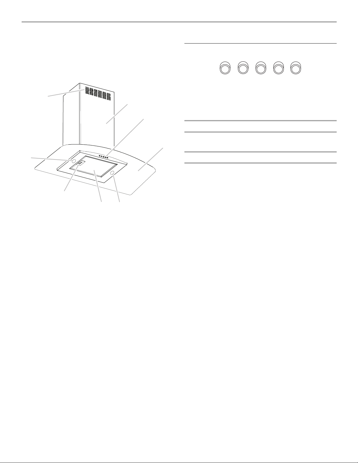
The hood controls are located on the front side of the canopy.
Range Hood Controls
A. On/Off light button
B. Blower Off button
C. Blower speed minimum button
D. Blower speed medium button
E. Blower speed maximum button
Operating the light
The On/Off light button controls both lights. Press once for On
and again for Off.
Operating the blower
The Blower Speed buttons turn the blower on and control the
blower speed and sound level for quiet operation. The speed can
be changed anytime during fan operation by pressing the desired
blower speed button.
The Blower Off button turns the blower Off.
A. Duct cover holes
B. Duct cover
C. Control panel
D. Glass canopy
E. Halogen lamps
F. Grease filter
G. Grease filter release handle
13
Page 14
RANGE HOOD CARE
A
Cleaning
IMPORTANT: Clean the hood and grease filters frequently
according to the following instructions. Replace grease filters
before operating hood.
Exterior Surfaces:
To avoid damage to the exterior surface, do not use steel wool or
soap-filled scouring pads.
Always wipe dry to avoid water marks.
Cleaning Method:
■ Liquid detergent soap and water, or all-purpose cleanser
■ Wipe with damp soft cloth or nonabrasive sponge, then rinse
with clean water and wipe dry.
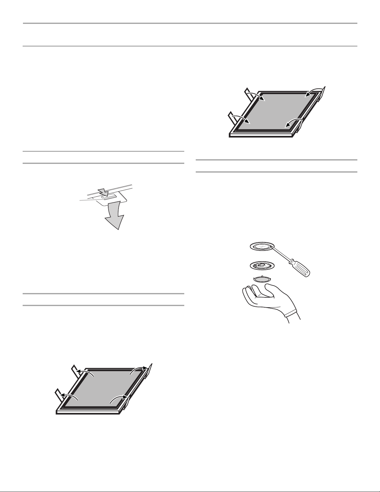
Metal Grease Filters
1. Remove each filter by pulling the spring release handle and
then pulling down the filter.
A. Spring release handle
3. Place charcoal filter into top side of metal filter.
4. Bend spring clips back into place to secure the charcoal filter
to the metal filter.
5. Replace metal grease filter. See “Metal Grease Filters” in this
section.
Replacing a Halogen Lamp
Turn off the range hood and allow the halogen lamp to cool. To
avoid damage or decreasing the life of the new bulb, do not
touch bulb with bare fingers. Replace bulb, using tissue or
wearing cotton gloves to handle bulb.
If new lights do not operate, make sure the lamps are inserted
correctly before calling service.
1. Disconnect power.
2. Use a flat-blade screwdriver and gently pry the light cover
loose.
2. Wash metal filters as needed in dishwasher or hot detergent
solution.
3. Reinstall the filter by making sure the spring release handles
are toward the front. Insert aluminum filter into upper track.
4. Push in spring release handle.
5. Push up on metal filter and release handle to latch into place.
Non-Vented (recirculating) Installation Filters
The charcoal filter is not washable. It should last up to 6 months
with normal use. Replace with Charcoal Filter Kit Number
W10412939.
To replace charcoal filter:
1. Remove metal grease filter from range hood. See “Metal
Grease Filters” in this section.
2. Bend spring clips away from metal grease filter.
3. Remove the lamp and replace with a 120-volt, 40-watt
maximum, halogen lamp made for a G-9 base.
4. Replace the light cover.
5. Reconnect power.
14
Page 15
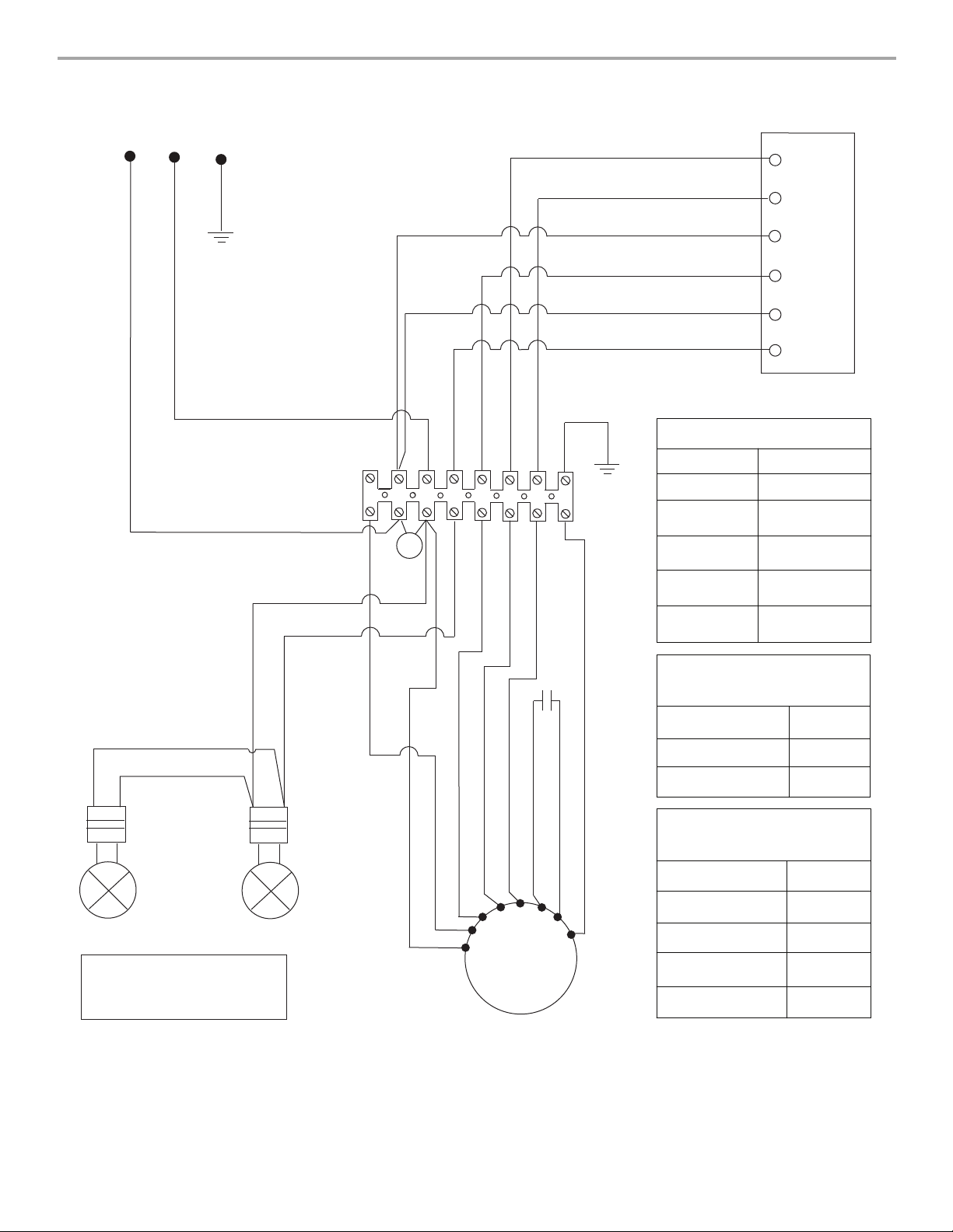
L
N
G
BK
WH
YL/GN
WH
YL/GN
RD
WH
BR
BK
BU
YL
Push Button Switch
2
1
L
3L
La
BK
YL
YL
YL
YL
SE123C
M
BR
WH
YL
BK
RD
WH
GY
N
BK
RD
WH
YL/GN
BU
YL
BR
YL/GN
BU
GY
BK
RD
WH
YL
BR
SWITCH OPERATION
POSITION
FUNCTION
Off
Lamps
Low Speed
Med Speed
High Speed
No Connection
Brown - Yellow
(L - LA)
Brown - White
(L - 1)
Brown - Red
(L - 2)
Brown - Black
(L - 3)
MOTOR
CHARACTERISTICS
Power Supply
Frequency
Power Absorption
240 Watts
120 VAC
60 Hz
MOTOR RESISTANCE
(Ohms)
Blue - Black
Blue - Gray
Blue - Red
Blue - White
Room Temp.
28.8
30.3
37.7
45.1
73.4ºF (23ºC)
WIRING DIAGRAM
15
Page 16

ASSISTANCE OR SERVICE
Before calling for assistance or service, please check to see
whether a circuit breaker has tripped or a household fuse has
blown. It may save you the cost of a service call. If you still need
help, follow the instructions below.
When calling, please know the purchase date and the complete
model and serial number of your appliance. This information will
help us to better respond to your request.
If you need replacement parts
If you need to order replacement parts, we recommend that you
use only factory specified
right and work right because they are made with the same
precision used to build every new IKEA
To locate factory specified parts in your area, call us or your
nearest designated service center.
Call the Whirlpool Customer eXperience Center
toll free: 1-866-664-2449.
Our consultants provide assistance with:
■ Features and specifications on our full line of appliances.
■ Installation information.
■ Use and maintenance procedures.
■ Accessory and repair parts sales.
■ Specialized customer assistance (Spanish speaking, hearing
impaired, limited vision, etc.).
■ Referrals to local dealers, repair parts distributors, and
service companies. Whirlpool designated service technicians
are trained to fulfill the product warranty and provide afterwarranty service, anywhere in the United States.
To locate the Whirlpool designated service company in your
area, you can also look in your telephone directory Yellow
Pages.
For further assistance
If you need further assistance, you can write to Whirlpool
Corporation with any questions or concerns at:
IKEA Brand Home Appliances
Customer eXperience Center
553 Benson Road
Benton Harbor, MI 49022-2692
Please include a daytime phone number in your correspondence.
parts. Factory specified parts will fit
®
appliance.
In the U.S.A.
In Canada
Call the Whirlpool Canada LP Customer eXperience Centre toll
free: 1-866-664-2449.
Our consultants provide assistance with:
■ Features and specifications on our full line of appliances.
■ Use and maintenance procedures.
■ Accessory and repair parts sales.
■ Referrals to local dealers, repair parts distributors, and
service companies. Whirlpool Canada LP designated service
technicians are trained to fulfill the product warranty and
provide after-warranty service, anywhere in Canada.
For further assistance
If you need further assistance, you can write to Whirlpool
Canada LP with any questions or concerns at:
Customer eXperience Centre
Whirlpool Canada LP
200 – 6750 Century Ave.
Mississauga, Ontario L5N 0B7
Please include a daytime phone number in your correspondence.
Accessories
Charcoal Filter Kit
(for non-vented installations only)
Order Part Number W10412939
Chimney Extension Kit
Order Part Number W10272078
6" (15.2 cm) Makeup Air Kit
(consult local building codes)
Order Part Number W10446915
16
Page 17

IKEA MAJOR APPLIANCE WARRANTY
How long is the IKEA limited warranty valid?
This limited warranty is valid for five years from the date of purchase, when this major appliance is operated and maintained according
to instructions attached to or furnished with the product, unless the appliance is named LAGAN in which case this limited warranty is
valid for one year from the date of purchase. This limited warranty is valid only in the United States or Canada and applies only when the
major appliance is used in the country in which it was purchased. Proof of original purchase date is required to obtain service under this
limited warranty.
Which appliances are not covered by the IKEA five (5) year limited warranty?
For major appliances named “LAGAN,” this limited warranty is valid for one year from the date of purchase.
Who will execute the service?
This limited warranty is provided by Whirlpool Corporation or Whirlpool Canada LP (hereafter “Whirlpool”). Service must be provided by
a Whirlpool designated service company.
What does this limited warranty cover?
The limited warranty will pay for factory specified parts and repair labor to correct defects in materials or workmanship that existed
when the major appliance was purchased. The exceptions are specified under the headline “What is not covered under this limited
warranty?”.
What will be done to correct the problem?
The designated service company will examine the product and decide, at its sole discretion, if it is covered under this limited warranty.
If considered covered, the designated service company will then repair the defect. Your sole and exclusive remedy under this limited
warranty shall be product repair as provided herein.
What is not covered under this limited warranty?
■ Service calls to correct the installation of your major appliance, to instruct you on how to use your major appliance, to replace or
repair house fuses, or to correct house wiring or plumbing.
■ Service calls to repair or replace appliance light bulbs, air filters or water filters. Consumable parts are excluded from warranty
coverage.
■ Replacement parts or repair labor if this major appliance is used for other than normal, single-family household use or when it is used
in a manner that is inconsistent to published user or operator instructions and/or installation instructions.
■ Damage resulting from accident, alteration, misuse, abuse, fire, flood, acts of God, improper installation, installation not in
accordance with electrical or plumbing codes, or use of consumables or cleaning products not approved for use.
■ Cosmetic damage, including scratches, dents, chips or other damage to the finish of your major appliance, unless such damage
results from defects in materials or workmanship and is reported within 30 days from the date of purchase.
■ Any food loss or medicine loss due to refrigerator or freezer product failures.
■ Pick up and delivery. This major appliance is intended to be repaired in your home.
■ Repairs to parts or systems resulting from unauthorized modifications made to the appliance.
■ Expenses for travel and transportation for product service if your major appliance is located in a remote area where service by an
authorized servicer is not available.
■ The removal and reinstallation of your major appliance if it is installed in an inaccessible location or is not installed in accordance with
published installation instructions.
■ Replacement parts or repair labor on major appliances with original model/serial numbers that have been removed, altered or cannot
be easily determined.
The cost of repair or replacement under these excluded circumstances shall be borne by the customer.
Disclaimer of Implied Warranties
IMPLIED WARRANTIES, INCLUDING ANY IMPLIED WARRANTY OF MERCHANTABILITY OR IMPLIED WARRANTY OF FITNESS FOR
A PARTICULAR PURPOSE, ARE LIMITED TO FIVE YEARS (ONE YEAR FOR MAJOR APPLIANCES NAMED “LAGAN”) OR THE
SHORTEST PERIOD ALLOWED BY LAW. Some states and provinces do not allow limitations on the duration of implied warranties of
merchantability or fitness, so this limitation may not apply to you. This warranty gives you specific legal rights, and you also may have
other rights that vary from state to state or province to province.
Limitation of Remedies; Exclusion of Incidental and Consequential Damages
YOUR SOLE AND EXCLUSIVE REMEDY UNDER THIS LIMITED WARRANTY SHALL BE PRODUCT REPAIR AS PROVIDED HEREIN.
WHIRLPOOL SHALL NOT BE LIABLE FOR INCIDENTAL OR CONSEQUENTIAL DAMAGES. Some states and provinces do not allow
the exclusion or limitation of incidental or consequential damages, so these limitations and exclusions may not apply to you. This
warranty gives you specific legal rights, and you also may have other rights that vary from state to state or province to province.
How to reach us if you need our service
If outside the 50 United States and Canada, contact your authorized IKEA retailer to determine if another warranty applies.
If you need service, please read the Installation Instructions and/or the “Troubleshooting” section of the Use & Care Guide before
contacting us. If you need additional help, do not hesitate to contact us in the U.S.A. and Canada at 1-866-664-2449.
2/09
17
Page 18

Keep this book and your sales slip together for future
reference. You must provide proof of purchase or installation
date for in-warranty service.
Write down the following information about your major appliance
to better help you obtain assistance or service if you ever need it.
You will need to know your complete model number and serial
number. You can find this information on the model and serial
number label located on the product.
Dealer name____________________________________________________
Address________________________________________________________
Phone number__________________________________________________
Model number __________________________________________________
Serial number __________________________________________________
Purchase date __________________________________________________
18
Page 19

Comment nous contacter si vous avez besoin d'une intervention d'entretien ou de réparation
W10502581H
© 2014.
All rights reserved.
Todos los derechos reservados.
Tous droits réservés.
® IKEA is a registered trademark of Inter-Ikea Systems B.V.
® IKEA es una marca registrada de Inter-Ikea Systems B.V.
® IKEA est une marque déposée de Inter-Ikea Systems B.V.
12/14
Printed in Mexico
Impreso en México
Imprimé au Mexique
Si vous résidez à l'extérieur des 50 États des États-Unis et du Canada, contactez votre marchand IKEA autorisé pour déterminer si une
autre garantie s'applique.
Si vous avez besoin d'une intervention d'entretien ou de réparation, veuillez lire les Instructions d'installation et/ou la section
“Dépannage” dans le Guide d'utilisation et d'entretien avant de nous contacter. Si vous avez besoin d'aide supplémentaire, n'hésitez
pas à nous contacter aux États-Unis et au Canada au 1-866-664-2449.
3/09
Conservez ce manuel et votre reçu de vente ensemble pour
référence ultérieure. Pour le service sous garantie, vous
devez présenter un document prouvant la date d'achat ou
d'installation.
Inscrivez les renseignements suivants au sujet de votre gros
appareil ménager pour mieux vous aider à obtenir assistance ou
service en cas de besoin. Vous devrez connaître le numéro de
modèle et le numéro de série au complet. Vous trouverez ces
renseignements sur la plaque signalétique située sur le produit.
Nom du marchand ______________________________________________
Adresse ________________________________________________________
Numéro de téléphone ___________________________________________
Numéro de modèle______________________________________________
Numéro de série ________________________________________________
Date d’achat____________________________________________________
 Loading...