

Page 1
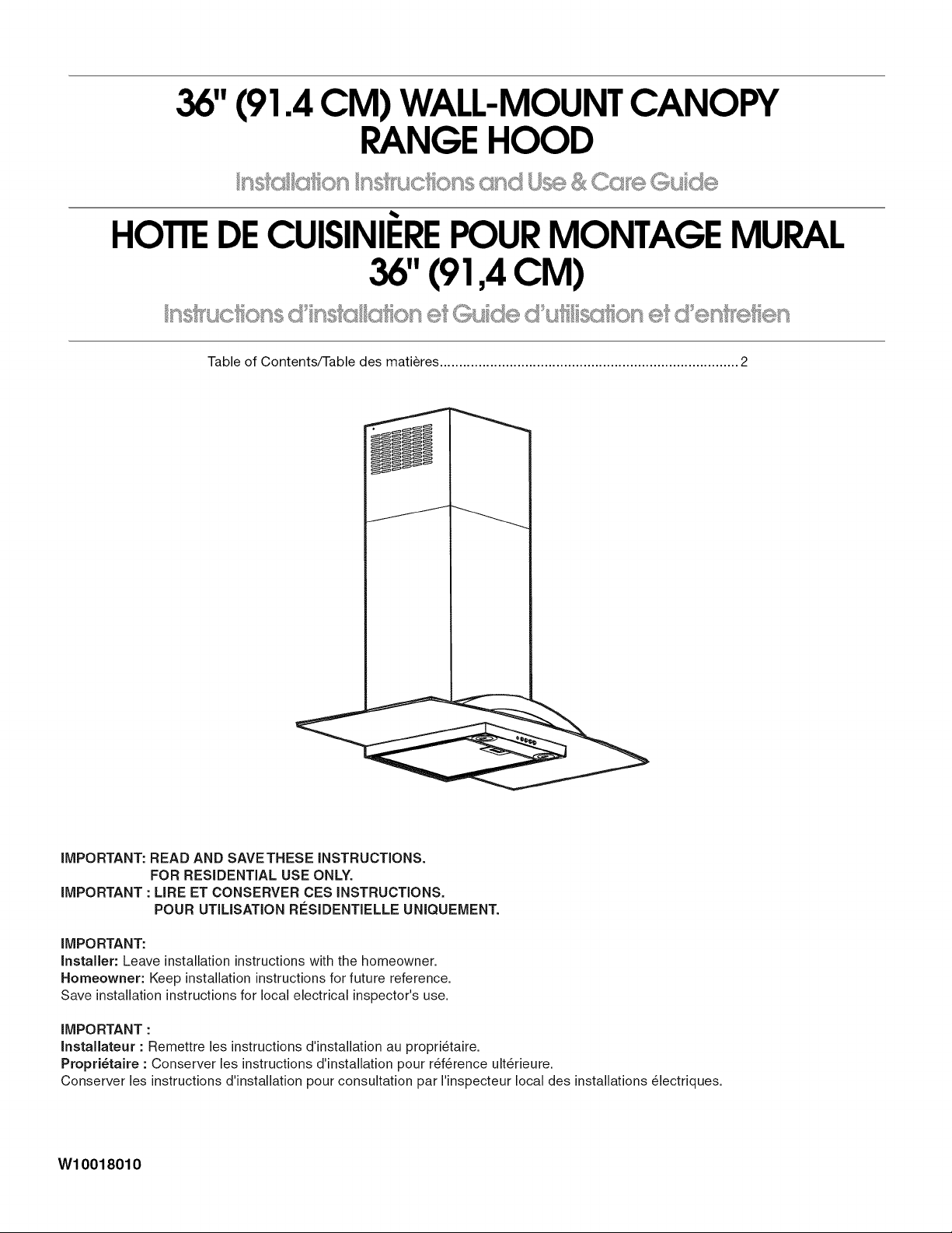
36"(91.4 CM) WALL-MOUNTCANOPY
RANGE HOOD
HOTTEDECUISINIEREPOURMONTAGE MURAL
36"(91,4 CM)
Table of Contents/Table des matieres ............................................................................. 2
IMPORTANT: READ AND SAVETHESE INSTRUCTIONS.
FOR RESIDENTIAL USE ONLY.
IMPORTANT : URE ET CONSERVER CES INSTRUCTIONS.
POUR UTILISATION RCSIDENTIELLE UNIQUEMENT.
IMPORTANT:
Installer: Leave installation instructions with the homeowner.
Homeowner: Keep installation instructions for future reference.
Save installation instructions for local electrical inspector's use.
IMPORTANT :
InstaJlateur : Remettre les instructions d'installation au propri_taire.
Propri_taire : Conserver les instructions d'installation pour r_f@ence ult@ieure.
Conserver les instructions d'installation pour consultation par I'inspecteur local des installations _lectriques.
W10018010
Page 2
TABLEOF CONTENTS
TABLEDESMATIERES
RANGE HOOD SAFETY ................................................................. 2
INSTALLATION REQUIREMENTS ................................................ 4
Tools and Parts ............................................................................ 4
Location Requirements ................................................................ 4
Venting Requirements .................................................................. 5
Electrical Requirements ............................................................... 6
INSTALLATION INSTRUCTIONS .................................................. 6
Prepare Location .......................................................................... 6
Install Range Hood ....................................................................... 7
Connect Vent System .................................................................. 8
Make Electrical Connection ......................................................... 8
Complete Installation ................................................................... 9
Install Filters ................................................................................ 10
Check Operation ........................................................................ 10
RANGE HOOD USE ...................................................................... 10
Operation .................................................................................... 10
RANGE HOOD CARE ................................................................... 11
Cleaning ...................................................................................... 11
WIRING DIAGRAM ...................................................................... 12
ASSISTANCE OR SERVICE ......................................................... 13
In the U.S.A................................................................................ 13
In Canada ................................................................................... 13
WAR RANTY .................................................................................. 14
SECURITE DE LA HOTTE DE CUlSINIERE ............................... 15
EXIGENCES D'INSTALLATION ................................................... 17
Outillage et pieces ...................................................................... 17
Exigences d'emplacement ......................................................... 17
Exigences concernant I'evacuation ........................................... 18
Specifications electriques .......................................................... 19
INSTRUCTIONS D'INSTALLATION ............................................. 20
Preparation de I'emplacement ................................................... 20
Installation de la hotte ............................................................... 21
Raccordement du circuit d'evacuation ...................................... 22
Raccordement electrique ........................................................... 22
Achever I'installation.................................................................. 23
Installation des filtres .................................................................. 24
Contr61e du fonctionnement ...................................................... 24
UTILISATION DE LA HOTTE ....................................................... 24
Fonctionnement ......................................................................... 24
ENTRETIEN DE LA Ho'n'E .......................................................... 25
Nettoyage ................................................................................... 25
SCHEMA DE C.&,BLAGE .............................................................. 26
ASSISTANCE OU SERVICE ......................................................... 27
GARANTIE .................................................................................... 28
RANGE HOOD SAFETY
Your safety and the safety of others are very important.
We have provided many important safety messages in this manual and on your appliance. Always read and obey all safety
messages.
This is the safety alert symbol.
This symbol alerts you to potential hazards that can kill or hurt you and others.
All safety messages will follow the safety alert symbol and either the word "DANGER" or "WARNING."
These words mean:
You can be killed or seriously injured if you don't immediately
follow instructions.
You can be killed or seriously injured if you don't follow
instructions.
All safety messages will tell you what the potential hazard is, tell you how to reduce the chance of injury, and tell you what can
happen if the instructions are not followed.
2
Page 3
iMPORTANT SAFETY iNSTRUCTiONS
WARNING: TO REDUCE THE RISK OF FIRE, ELECTRIC
SHOCK, OR INJURY TO PERSONS, OBSERVE THE
FOLLOWING:
[] Use this unit only in the manner intended by the
manufacturer. If you have questions, contact the
manufacturer.
[] Before servicing or cleaning the unit, switch the power off at
the service panel disconnecting means to prevent power
from being switched on accidentally. When the service
disconnecting means cannot be locked, securely fasten a
prominent warning device, such as a tag, to the service
panel.
[] Installation work and electrical wiring must be done by
qualified person(s) in accordance with all applicable codes
& standards, including fire-rated construction.
[] Sufficient air is needed for proper combustion and
exhausting of gases through the flue (chimney) of fuel
burning equipment to prevent backdrafting. Follow the
heating equipment manufacturer's guideline and safety
standards such as those published by the National Fire
Protection Association (NFPA), the American Society for
Heating, Refrigeration and Air Conditioning Engineers
(ASHRAE), and the local code authorities.
[] When cutting or drilling into wall or ceiling; do not damage
electrical wiring and other utilities.
[] Ducted systems must always be vented outdoors.
CAUTION: For general ventilating use only. Do not use
to exhaust hazardous or explosive materials and vapors.
CAUTION: To reduce risk of fire and to properly exhaust
air, be sure to duct air outside - do not vent exhaust air into
spaces within walls ceilings, attics, crawl spaces, or
garages.
WARNING: TO REDUCE THE RISK OF FIRE, USE ONLY
METAL DUCTWORK.
WARNING: TO REDUCE THE RISK OF A RANGE TOP
GREASE FIRE:
[] Never leave the surface units unattended at high settings.
Boilovers cause smoking and greasy spillovers that may
ignite. Heat oils slowly on low or medium settings.
[] Always turn hood ON when cooking at high heat or when
flambeing food (i.e. Crepes Suzette, Cherries Jubilee,
Peppercorn Beef Flamb6).
[] Clean ventilating fans frequently. Grease should not be
allowed to accumulate on fan or filter.
[] Use proper pan size. Always use cookware appropriate for
the size of the surface element.
WARNING: TO REDUCE THE RISK OF INJURY TO
PERSONS IN THE EVENT OF A RANGE TOP GREASE
FIRE, OBSERVE THE FOLLOWING: a
[] SMOTHER FLAMES with a close fitting lid, cookie sheet, or
other metal tray, then turn off the gas burner or electric
element. BE CAREFUL TO PREVENT BURNS. If the
flames do not go out immediately, EVACUATE AND CALL
THE FIRE DEPARTMENT.
[] NEVER PICK UP A FLAMING PAN - you may be burned.
[] DO NOT USE WATER, including wet dishcloths or towels -
a violent steam explosion will result.
[] Use an extinguisher ONLY if:
- You know you have a class ABC extinguisher, and you
already know how to operate it.
- The fire is small and contained in the area where it
started.
- The fire department is being called.
- You can fight the fire with your back to an exit.
aBased on "Kitchen Fire Safety Tips" published by NFPA.
[] WARNING: To reduce the risk of fire or electrical shock,
do not use this fan with any solid-state speed control
device.
SAVE THESE iNSTRUCTiONS
Page 4
INSTALLATIONREQUIREMENTS
Gather the required tools and parts before starting installation.
Read and follow the instructions provided with any tools listed
here.
Tools needed
• Level
• Drill with 1%" (3 cm), 3/8"(9.5 mm), %4" (2.75 mm) and
V8"(3 mm) drill bits
• Pencil
• Wire stripper or utility knife
• Tape measure or ruler
• Pliers
• Caulking gun and weatherproof caulking compound
• Vent clamps
• Jigsaw or keyhole saw
• Flat-blade screwdriver
• Metal snips
• Phillips screwdriver
Parts needed
• V2" conduit
• Two 1/2"(12.7 mm) UL listed or CSA approved strain reliefs
• 3 UL listed wire connectors
• 1 wall or roof cap
• Metal vent system
• Charcoal Filter Kit Part Number 4396850 - for non-vented
(recirculating) installations only. See "Assistance or Service"
section to order.
Parts supplied
Remove parts from packages. Check that all parts are included.
• Hood canopy assembly with ventilator, light bulbs and
transition with back draft dampers installed
• Deflector for non-vented (recirculating) installations
• Literature package
• Filter- installed in hood canopy
• 2-5x35mmscrews
• 4-4x8mmscrews
• 2-6x70mmscrews
• 6- 3.5 x 6.5 mm screws
• 4- 2.9 x 6.5 mm screws
• 3- M4 x 35 mm screws
• 2 - 10 x 70 drywall anchors
• Mounting template
• Lower support bracket
• Vent cover bracket
• 2- L-brackets
• 2- Mounting hooks
• 2-piece vent cover
• Aesthetic cover
• Rubber strip (1 or 2 to be cut as required)
IMPORTANT: Observe all governing codes and ordinances.
Have a qualified technician install the range hood. It is the
installer's responsibility to comply with installation clearances
specified on the model/serial rating plate. The model/serial rating
plate is located behind the filter on the rear wall of the range
hood.
Range hood location should be away from strong draft areas,
such as windows, doors and strong heating vents.
Cabinet opening dimensions that are shown must be used. Given
dimensions provide minimum clearance.
Grounded electrical outlet is required. See "Electrical
Requirements" section.
The range hood is factory set for venting through the roof or wall.
For non-vented (recirculating) installations see "Non-vented
(recirculating) Installations" in "Connect Vent System" section.
Charcoal Filter Kit Part Number 4396850 is available from your
dealer or an authorized parts distributor.
All openings in ceiling and wall where range hood will be installed
must be sealed.
For Mobile Home Installations
The installation of this range hood must conform to the
Manufactured Home Construction Safety Standards, Title 24
CFR, Part 328 (formerly the Federal Standard for Mobile Home
Construction and Safety, Title 24, HUD, Part 280) or when such
standard is not applicable, the standard for Manufactured Home
Installation 1982 (Manufactured Home Sites, Communities and
Setups) ANSI A225.1/NFPA 501A*, or latest edition, or with local
codes.
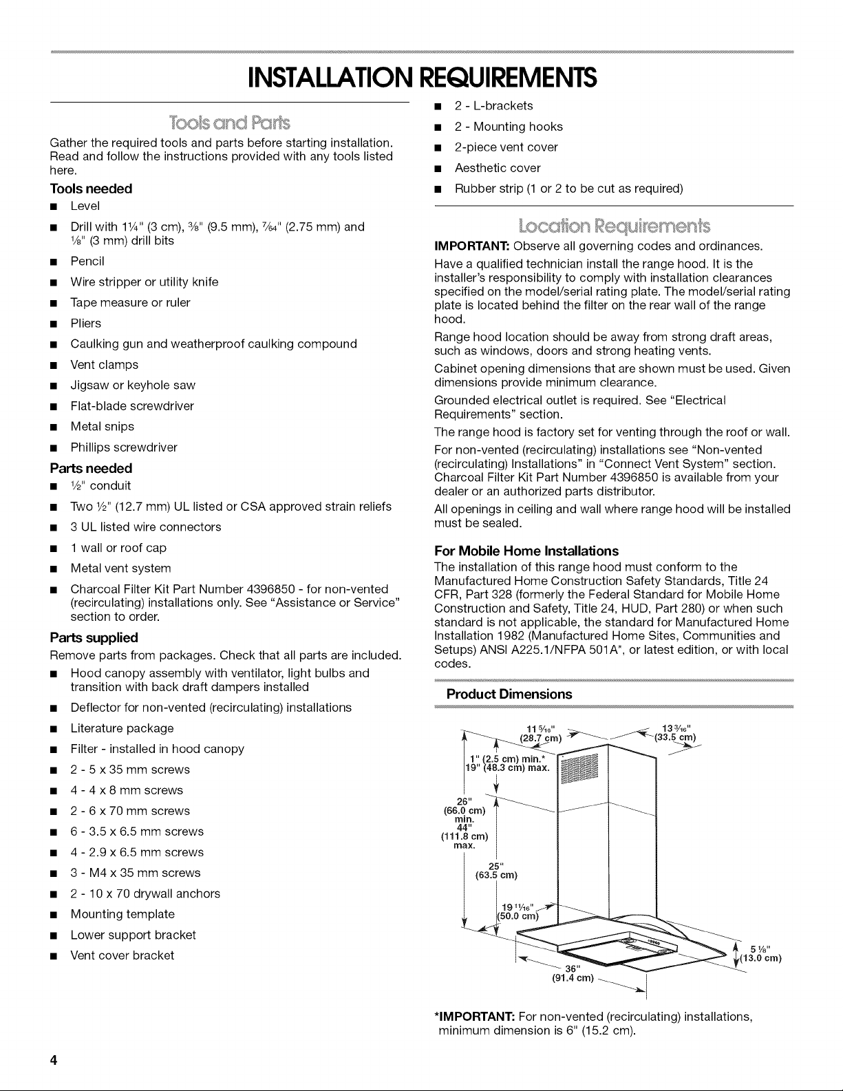
Product Dimensions
*IMPORTANT: For non-vented (recirculating) installations,
minimum dimension is 6" (15.2 cm).
Page 5
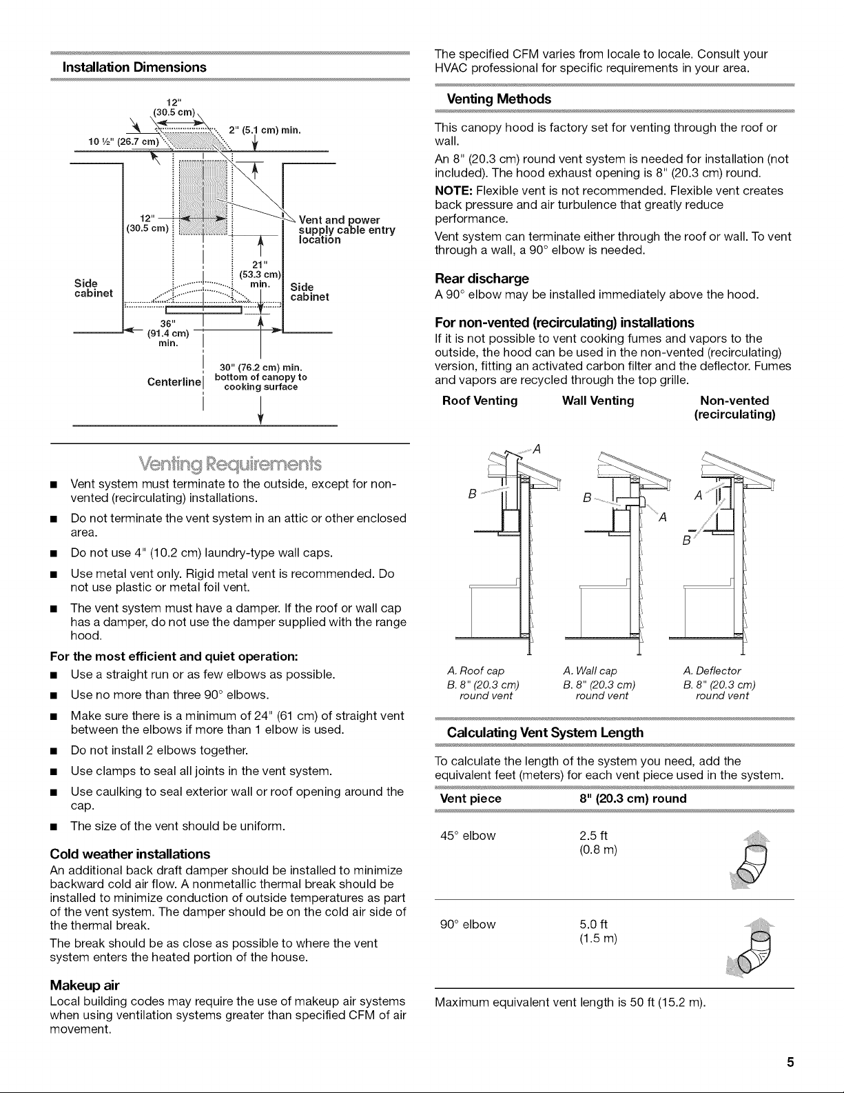
Installation Dimensions
The specified CFM varies from locale to locale. Consult your
HVAC professional for specific requirements in your area.
12"
10 1/2" (26.7 cm)
(30.5 cm)
Side
cabinet
--_ (91.4 cm) i --
36" I l
mJn.
J 30" (76.2 cm) rain.
Centerline I bottom of canopy to
cm) ram.
21"
i (s3.3cm)
cooking surface
30 power
supply cabJe entry
location
Side
cabinet
i
• Vent system must terminate to the outside, except for non-
vented (recirculating) installations.
• Do not terminate the vent system in an attic or other enclosed
area.
• Do not use 4" (10.2 cm) laundry-type wall caps.
• Use metal vent only. Rigid metal vent is recommended. Do
not use plastic or metal foil vent.
• The vent system must have a damper. If the roof or wall cap
has a damper, do not use the damper supplied with the range
hood.
For the most efficient and quiet operation:
• Use a straight run or as few elbows as possible.
• Use no more than three 90° elbows.
• Make sure there is a minimum of 24" (61 cm) of straight vent
between the elbows if more than 1 elbow is used.
• Do not install 2 elbows together.
• Use clamps to seal all joints in the vent system.
• Use caulking to seal exterior wall or roof opening around the
cap.
• The size of the vent should be uniform.
Cold weather installations
An additional back draft damper should be installed to minimize
backward cold air flow. A nonmetallic thermal break should be
installed to minimize conduction of outside temperatures as part
of the vent system. The damper should be on the cold air side of
the thermal break.
The break should be as close as possible to where the vent
system enters the heated portion of the house.
Venting Methods
This canopy hood is factory set for venting through the roof or
wall.
An 8" (20.3 cm) round vent system is needed for installation (not
included). The hood exhaust opening is 8" (20.3 cm) round.
NOTE: Flexible vent is not recommended. Flexible vent creates
back pressure and air turbulence that greatly reduce
performance.
Vent system can terminate either through the roof or wall. To vent
through a wall, a 90° elbow is needed.
Rear discharge
A 90° elbow may be installed immediately above the hood.
For non-vented (recirculating) installations
If it is not possible to vent cooking fumes and vapors to the
outside, the hood can be used in the non-vented (recirculating)
version, fitting an activated carbon filter and the deflector. Fumes
and vapors are recycled through the top grille.
Roof Venting Wall Venting Non-vented
(recirculating)
..........A
A ...........
J!
A. Roof cap A. Wall cap A. Deflector
B. 8" (20.3 cm) B. 8" (20.3 cm) B. 8" (20.3 cm)
round vent round vent round vent
Calculating Vent System Length
To calculate the length of the system you need, add the
equivalent feet (meters) for each vent piece used in the system.
Vent piece 8" (20.3 cm) round
45° elbow 2.5 ft
(0.8 m)
90° elbow 5.0 ft
(1.5 m)
Makeup air
Local building codes may require the use of makeup air systems
when using ventilation systems greater than specified CFM of air
movement.
Maximum equivalent vent length is 50 ft (15.2 m).
Page 6
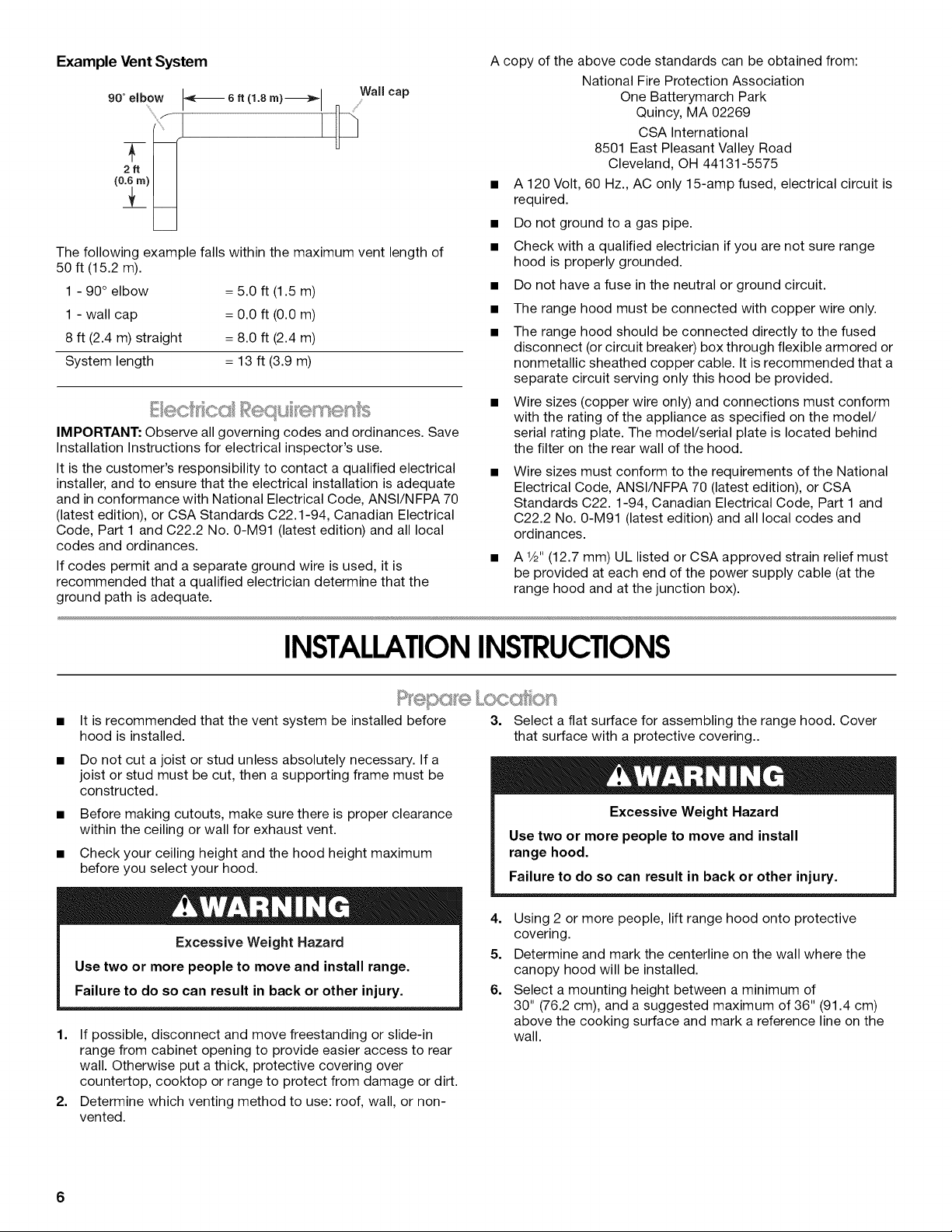
Example Vent System
,o ° elbow I-_-_ 6. (_.8m)-_,,_l Wall cap
The following example falls within the maximum vent length of
50 ft (15.2 m).
1 - 90° elbow
1 - wall cap
8 ft (2.4 m) straight
System length
IMPORTANT: Observe all governing codes and ordinances. Save
Installation Instructions for electrical inspector's use.
It is the customer's responsibility to contact a qualified electrical
installer, and to ensure that the electrical installation is adequate
and in conformance with National Electrical Code, ANSI/NFPA 70
(latest edition), or CSA Standards C22.1-94, Canadian Electrical
Code, Part 1 and C22.2 No. 0-M91 (latest edition) and all local
codes and ordinances.
If codes permit and a separate ground wire is used, it is
recommended that a qualified electrician determine that the
ground path is adequate.
= 5.0 ft (1.5 m)
= 0.0 ft (0.0 m)
= 8.0 ft (2.4 m)
= 13 ft (3.9 m)
A copy of the above code standards can be obtained from:
National Fire Protection Association
One Batterymarch Park
Quincy, MA 02269
CSA International
8501 East Pleasant Valley Road
Cleveland, OH 44131-5575
• A 120 Volt, 60 Hz., AC only 15-amp fused, electrical circuit is
required.
• Do not ground to a gas pipe.
• Check with a qualified electrician if you are not sure range
hood is properly grounded.
• Do not have a fuse in the neutral or ground circuit.
• The range hood must be connected with copper wire only.
• The range hood should be connected directly to the fused
disconnect (or circuit breaker) box through flexible armored or
nonmetallic sheathed copper cable. It is recommended that a
separate circuit serving only this hood be provided.
• Wire sizes (copper wire only) and connections must conform
with the rating of the appliance as specified on the model/
serial rating plate. The model/serial plate is located behind
the filter on the rear wall of the hood.
Wire sizes must conform to the requirements of the National
Electrical Code, ANSl/NFPA 70 (latest edition), or CSA
Standards C22.1-94, Canadian Electrical Code, Part 1 and
C22.2 No. 0-M91 (latest edition) and all local codes and
ordinances.
• A W' (12.7 mm) UL listed or CSA approved strain relief must
be provided at each end of the power supply cable (at the
range hood and at the junction box).
INSTALLATIONINSTRUCTIONS
It is recommended that the vent system be installed before
hood is installed.
Do not cut a joist or stud unless absolutely necessary. If a
joist or stud must be cut, then a supporting frame must be
constructed.
• Before making cutouts, make sure there is proper clearance
within the ceiling or wall for exhaust vent.
• Check your ceiling height and the hood height maximum
before you select your hood.
Excessive Weight Hazard
Use two or more people to move and install range.
Failure to do so can result in back or other injury.
1. If possible, disconnect and move freestanding or slide-in
range from cabinet opening to provide easier access to rear
wall. Otherwise put a thick, protective covering over
countertop, cooktop or range to protect from damage or dirt.
2. Determine which venting method to use: roof, wall, or non-
vented.
3. Select a flat surface for assembling the range hood. Cover
that surface with a protective covering..
Excessive Weight Hazard
Use two or more people to move and install
range hood.
Failure to do so can result in back or other injury.
4. Using 2 or more people, lift range hood onto protective
covering.
5. Determine and mark the centerline on the wall where the
canopy hood will be installed.
6. Select a mounting height between a minimum of
30" (76.2 cm), and a suggested maximum of 36" (91.4 cm)
above the cooking surface and mark a reference line on the
wall.
6
Page 7
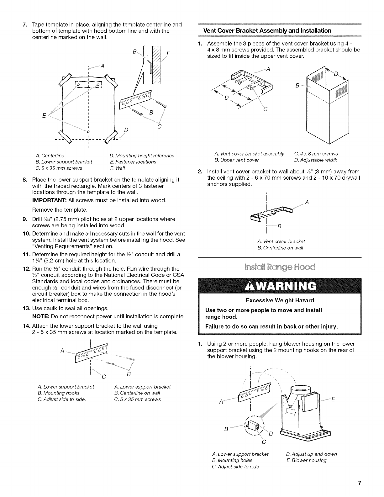
7,
Tape template in place, aligning the template centerline and
bottom of template with hood bottom line and with the
centerline marked on the wall.
¸%%¸¸¸ i/iF
Vent Cover Bracket Assembly and Installation
1. Assemble the 3 pieces of the vent cover bracket using 4 -
4 x 8 mm screws provided. The assembled bracket should be
sized to fit inside the upper vent cover.
I
J
D
A. Centerline
B. Lower support bracket
C. 5 x 35 mm screws
8=
Place the lower support bracket on the template aligning it
D. Mounting height reference
E. Fastener locations
F Wall
C
with the traced rectangle. Mark centers of 3 fastener
locations through the template to the wall.
IMPORTANT: All screws must be installed into wood.
Remove the template.
9. Drill %4" (2.75 mm) pilot holes at 2 upper locations where
screws are being installed into wood.
10. Determine and make all necessary cuts in the wall for the vent
system. Install the vent system before installing the hood. See
"Venting Requirements" section.
11. Determine the required height for the 1/2"conduit and drill a
11¼"(3.2 cm) hole at this location.
12. Run the 1/2"conduit through the hole. Run wire through the
1/2"conduit according to the National Electrical Code or CSA
Standards and local codes and ordinances. There must be
enough 1/2"conduit and wires from the fused disconnect (or
circuit breaker) box to make the connection in the hood's
electrical terminal box.
13. Use caulk to seal all openings.
NOTE: Do not reconnect power until installation is complete.
14. Attach the lower support bracket to the wall using
2 - 5 x 35 mm screws at location marked on the template.
A. Vent cover bracket assembly
B. Upper vent cover
2=
Install vent cover bracket to wall about 1/8"(3 mm) away from
C. 4 x 8 mm screws
D. Adjustable width
the ceiling with 2 - 6 x 70 mm screws and 2 - 10 x 70 drywall
anchors supplied.
i
i ...............................g
I
A. Vent cover bracket
B. Centerline on wall
Excessive Weight Hazard
Use two or more people to move and install
range hood.
Failure to do so can result in back or other injury.
A. Lower support bracket
B. Mounting hooks
C. Adjust side to side.
A. Lower support bracket
B. Centerline on wall
C. 5 x 35 mm screws
1,
Using 2 or more people, hang blower housing on the lower
support bracket using the 2 mounting hooks on the rear of
the blower housing.
A. Lower support bracket
B. Mounting holes
C. Adjust side to side
D.Adjust up and down
E. Blower housing
Page 8
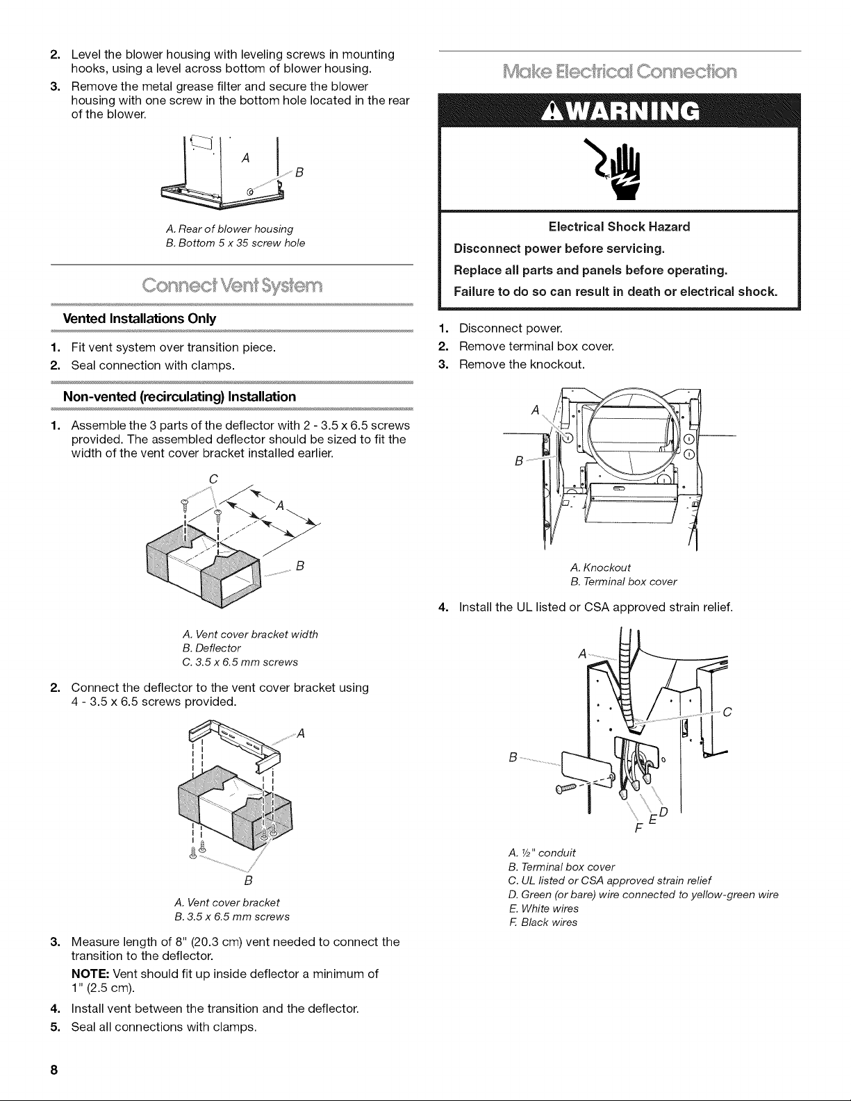
2. Level the blower housing with leveling screws in mounting
hooks, using a level across bottom of blower housing.
3. Remove the metal grease filter and secure the blower
housing with one screw in the bottom hole located in the rear
of the blower.
4_" Ac__, B
Mc <® Eecff ccl Connec on
A. Rear of blower housing
B. Bottom 5 x 35 screw hole
_,_,_o_F_s_'@C_@ _/s@_ +_
Vented Installations Only
1. Fit vent system over transition piece.
2. Seal connection with clamps.
Non-vented (recirculating} Installation
1. Assemble the 3 parts of the deflector with 2 - 3.5 x 6.5 screws
provided. The assembled deflector should be sized to fit the
width of the vent cover bracket installed earlier.
C
B
Electrical Shock Hazard
Disconnect power before servicing.
Replace all parts and panels before operating.
Failure to do so can result in death or electrical shock.
1. Disconnect power.
2. Remove terminal box cover.
3. Remove the knockout.
A
S ....
A. Knockout
B. Terminal box cover
4. Install the UL listed or CSA approved strain relief.
A. Vent cover bracket width
B. Deflector
C. 3.5 x 6.5 mm screws
2=
Connect the deflector to the vent cover bracket using
4 - 3.5 x 6.5 screws provided.
B
A. Vent cover bracket
B. 3.5 x 6.5 mm screws
3. Measure length of 8" (20.3 cm) vent needed to connect the
transition to the deflector.
NOTE: Vent should fit up inside deflector a minimum of
1" (2.5 cm).
4. Install vent between the transition and the deflector.
5. Seal all connections with clamps.
F
A. Y2"conduit
B. Terminal box cover
C. UL fisted or CSA approved strain relief
D. Green (or bare) wire connected to yellow-green wire
E. White wires
F. Black wires
8
Page 9
5. Run 3 wires, black, white and green (14 AWG), in 1/2"conduit
from service panel to terminal box.
6. Use UL listed wire connectors and connect black wires
together.
7. Use UL listed wire connectors and connect white wires
together.
Electrical Shock Hazard
Electrically ground blower.
Connect ground wire to green and yellow ground wire
in terminal box.
Failure to do so can result in death or electrical shock.
8. Connect ground wire to green and yellow ground wire in
terminal box using UL listed wire connectors.
9. Replace terminal box cover.
10. Check all light bulbs to make sure they are secure in their
sockets.
11. Reconnect power.
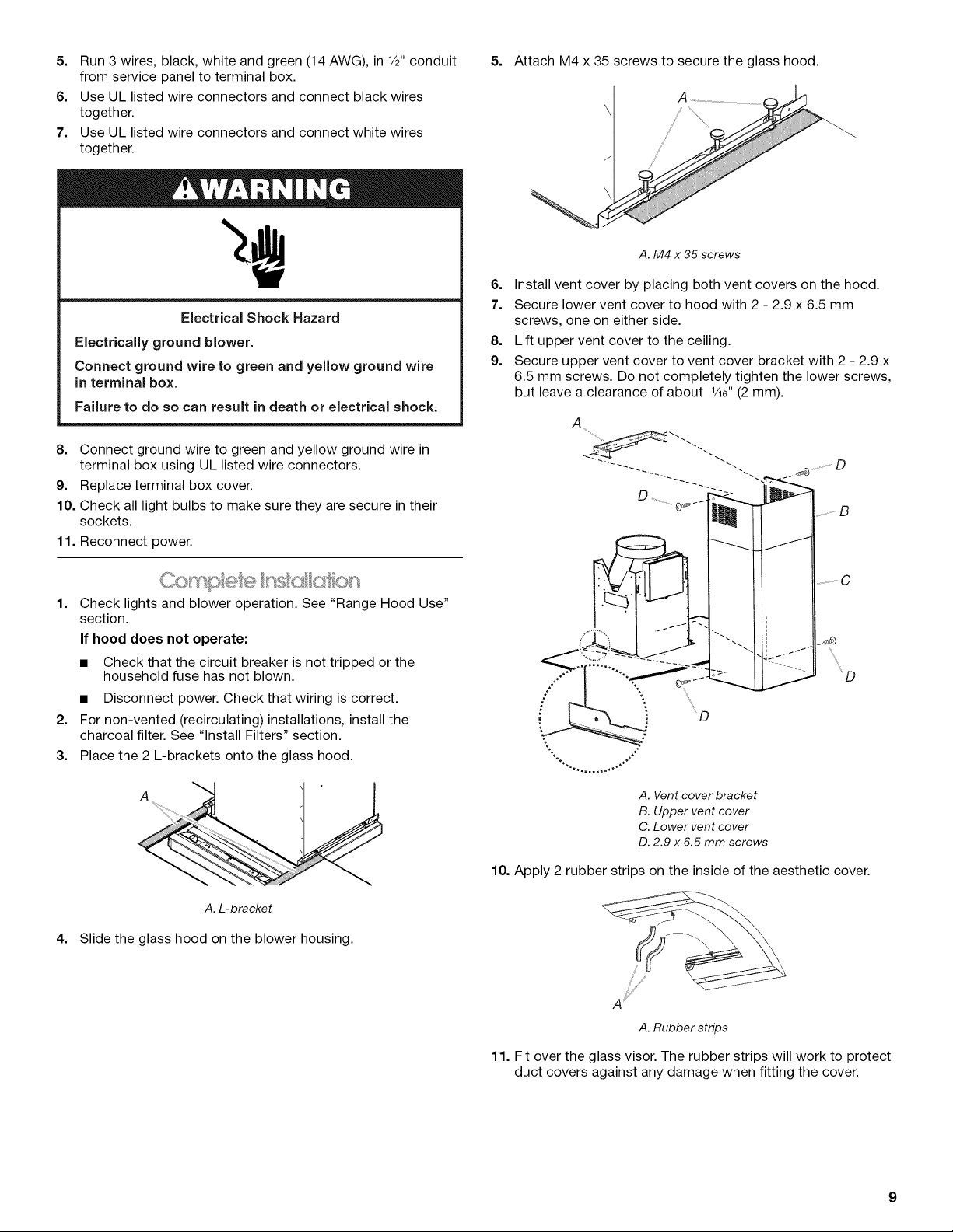
5. Attach M4 x 35 screws to secure the glass hood.
A
/
A. M4 x 35 screws
6. Install vent cover by placing both vent covers on the hood.
7. Secure lower vent cover to hood with 2 - 2.9 x 6.5 mm
screws, one on either side.
8. Lift upper vent cover to the ceiling.
9. Secure upper vent cover to vent cover bracket with 2 - 2.9 x
6.5 mm screws. Do not completely tighten the lower screws,
but leave a clearance of about V16"(2 mm).
A
1. Check lights and blower operation. See "Range Hood Use"
section.
If hood does not operate:
• Check that the circuit breaker is not tripped or the
household fuse has not blown.
• Disconnect power. Check that wiring is correct.
2. For non-vented (recirculating) installations, install the
charcoal filter. See "Install Filters" section.
3. Place the 2 L-brackets onto the glass hood.
A
A.L-bracket
4. Slide the glass hood on the blower housing.
A. Vent cover bracket
B. Upper vent cover
C. Lower vent cover
D. 2.9 x 6.5 mm screws
10. Apply 2 rubber strips on the inside of the aesthetic cover.
A _¸¸
A.Rubber strips
11. Fit over the glass visor. The rubber strips will work to protect
duct covers against any damage when fitting the cover.
Page 10

Whenfittingthecover,checkthatthesiderailsfitinthe
properhead-screws(thoseusedtofixthelowerventcoverto
thehood)ontherightandleftsideoftheduct.
Toreplacethemetalgreasefilters:
1. Insertbackedgeoffilterintorearchannelofthefilter
opening.
2. Pushhandletowardtherearandpushfilterup.
3. Pullfiltertowardthefrontandinsertintofrontchannel.
o ©@©@
B
/
/
C
A, Lower vent cover screws
B. Glass visor
C. Aesthetic cover
For non-vented (recirculating) installations
1. Turn off blower and lights. Check that halogen lamps are
cool.
2. Remove the metal grease filters by pushing handle toward
the rear and pull downward.
A B C D E
A. Indicator light
B. Light button
C. Low speed button
1. Press the "B" button. The light should turn on.
2. Press the "C" button. The blower should turn on at low
speed.
3. Press the "D" button for medium speed or the "E" button for
high speed.
4. Press the "B" button to turn off the light. Press the "C" button
to turn off blower
5. If range hood does not operate, check to see whether a
circuit breaker has tripped or a household fuse has blown.
6. Disconnect power supply.
7. Check that the wiring is correct.
8. Replace all parts and panels before operating.
9. Reconnect power.
NOTE: To get the most efficient use from your new range hood,
read the "Range Hood Use" section.
D. Medium speed button
E. High speed button
RANGE HOOD USE
3,
Pull filter toward front.
4.
Set the filter face down on a protective cover such as a towel.
5.
Install charcoal filter on rear of metal filter with metal wires
provided in filter packaging.
/
A. Metal wires
B. Charcoal filter
C. Metal filter
The canopy hood is designed to remove smoke, cooking vapors
and odors from the cooktop area. For best results, start the hood
before cooking and allow it to operate several minutes after the
cooking is complete to clear all smoke and odors from the
kitchen.
Range Hood Control Panel
The range hood controls are located on the underside of the
canopy.
o ©@©Q ]
A B C D E
A. Indicator light
B. Light button
C. Low speed button
Operating the light
1. Press the "B" button to turn on the light.
2. Press the "B" button again to turn off the light.
Operating the blower and adjusting blower speed
1. Press the "C" button for low speed, the "D" button for
medium speed or the "E" button for high speed.
2. Press the "C" button to turn off the blower.
D. Medium speed button
E. High speed button
10
Page 11

RANGE HOOD CARE
IMPORTANT: Clean the hood and grease filters frequently
according to the following instructions. Replace grease filters
before operating hood.
Check that lights are cool before cleaning the hood.
Exterior surfaces
Clean the range hood with a mild detergent and soft cloth. Do not
use abrasive cleanser or steel-wool pads.
Metal grease filters
The filters should be washed frequently. Place metal filters in
dishwasher or hot detergent solution to clean. Drain water
through edge holes and let each filter dry thoroughly before
replacing it.
To remove metal filters:
1. Turn off blower and lights. Check that the halogen lamp is
cool.
2. Push handle toward the rear and pull downward.
3. Pull filter toward the front.
To replace charcoal filter:
1. Turn off blower and lights. Check that range hood is off and
halogen lamp is cool.
2. Remove the metal grease filters by pushing handle toward
the rear and pull downward.
3. Pull filter toward front.
4. Set the filter face down on a protective cover such as a towel.
5. Remove metal wires and clean or discard charcoal filter.
6. Install cleaned or replacement charcoal filter on rear of metal
filter with metal wires provided in filter packaging.
To replace the metal grease filters:
1. Insert back edge of filter into rear track of the filter opening.
2. Push handle toward the rear and push filter up.
3. Pull filter toward the front and insert into front track.
Replacing a halogen lamp
Turn off the range hood and allow the halogen lamps to cool.
Replace bulb by using a tissue to handle bulb or while wearing
cotton gloves. Do not touch bulb with bare fingers.
If new lights do not operate, make sure the lamps are inserted
correctly before calling service.
1. Disconnect power.
2. Use a flat-blade screwdriver and gently pry the light cover
loose.
To replace the metal grease filter:
1. Insert back edge of filter into rear channel of the filter
opening.
2. Push handle toward the rear and push filter up.
3. Pull filter toward the front and insert into front channel.
Charcoal Filters - For non-vented (recirculating)
installations
The charcoal filters capture unpleasant cooking odors. They can
be cleaned and reactivated. With normal use the filter should be
cleaned every second month (when using the hood 2.5 hours per
day, on average).
Clean the filter in the dishwasher using normal detergent and
choosing the highest temperature setting. Wash the filter
separately. To reactivate the filter, the filter should be dried in
an oven for 10 minutes with a maximum temperature of
210°F (100°C).
After approximately 3 years of use, the charcoal filter should be
replaced. See "Assistance or Service" section to order
replacement charcoal filters.
3. Remove the lamp and replace with a 12-volt, 20-watt
maximum, halogen lamp made for a G-4 base.
4. Replace the light cover.
5. Reconnect power.
11
Page 12

WIRING DIAGRAM
SW1 SW2 SW3 SW4
L N $ Light OFF 0 x x x
___ Vel 1 x 1 0 0
Light ON 1 x x x
Vel 2 x 1 1 0
Vel 3 x 1 x 1
oNE]N N
SW1 SW2 SW3 SW4
BE07AA
W
SWx
[]
_iI O _Ol_l • 1-3 3-5
=
y
MOTOR
SPEED
1
2
3
4
CONNECTION
TO TERMINAL
blue(3)-white(7)
blue(3)-red(6)
blue(3(-green(5)
blue(3)-blank(4)
t YB
OHM RESISTANCE (Ohm)
BETWEEN TERMINALS
from 5.6 to 11.8 ohm
BK
BK
BU
Y Y
BR
12
Page 13

ASSISTANCEOR SERVICE
When calling for assistance or service, please know the purchase
date and the complete model and serial number of your
appliance. This information will help us to better respond to your
request.
If you need replacement parts
If you need to order replacement parts, we recommend that you
use only factory specified parts. Factory specified parts will fit
right and work right because they are made with the same
precision used to build every new appliance. To locate factory
specified parts replacement parts in your area, call us or your
nearest Whirlpool designated service center.
!_ _ _'_E _ _ _
f" USA
Call the Whirlpool Customer eXperience Center
toll free: 1-800-253-1301.
Our consultants provide assistance with:
• Features and specifications on our full line of appliances.
• Installation information.
• Use and maintenance procedures.
• Accessory and repair parts sales.
• Specialized customer assistance (Spanish speaking, hearing
impaired, limited vision, etc.).
• Referrals to local dealers, repair parts distributors and service
companies. Whirlpool designated service technicians are
trained to fulfill the product warranty and provide after-
warranty service, anywhere in the United States.
To locate the Whirlpool designated service company in your
area, you can also look in your telephone directory Yellow
Pages.
For further assistance
If you need further assistance, you can write to Whirlpool
Corporation with any questions or concerns at:
Whirlpool Brand Home Appliances
Customer eXperience Center
553 Benson Road
Benton Harbor, MI 49022-2692
Please include a daytime phone number in your correspondence.
Accessories List
Charcoal Filter Kit
Part Number 4396850
Call the Whirlpool Canada LP Customer Interaction Centre toll
free: 1-800-807-6777.
Our consultants provide assistance with:
• Features and specifications on our full line of appliances.
• Use and maintenance procedures.
• Accessory and repair parts sales.
• Referrals to local dealers, repair parts distributors, and
service companies. Whirlpool Canada LP designated service
technicians are trained to fulfill the product warranty and
provide after-warranty service, anywhere in Canada.
For further assistance
If you need further assistance, you can write to Whirlpool
Canada LP with any questions or concerns at:
Customer Interaction Centre
Whirlpool Canada LP
1901 Minnesota Court
Mississauga, Ontario L5N 3A7
Please include a daytime phone number in your correspondence.
13
Page 14

WHIRLPOOLCORPORATIONMAJOR APPLIANCEWARRANTY
ONE YEAR LIMITED WARRANTY
For one year from the date of purchase, when this major appliance is operated and maintained according to instructions attached to or
furnished with the product, Whirlpool Corporation or Whirlpool Canada LP (hereafter "Whirlpool") will pay for Factory Specified Parts
and repair labor to correct defects in materials or workmanship. Service must be provided by a Whirlpool designated service company.
This limited warranty applies only when the major appliance is used in the country in which it was purchased.
ITEMS WHIRLPOOL WILL NOT PAY FOR
1. Service calls to correct the installation of your major appliance, to instruct you how to use your major appliance, to replace or repair
house fuses or to correct house wiring or plumbing.
2. Service calls to repair or replace appliance light bulbs, air filters or water filters. Those consumable parts are excluded from warranty
coverage.
3. Repairs when your major appliance is used for other than normal, single-family household use.
4. Damage resulting from accident, alteration, misuse, abuse, fire, flood, acts of God, improper installation, installation not in
accordance with electrical or plumbing codes, or use of products not approved by Whirlpool.
5. Any food loss due to refrigerator or freezer product failures.
6. Replacement parts or repair labor costs for units operated outside the United States or Canada.
7. Pickup and delivery. This major appliance is designed to be repaired in the home.
8. Repairs to parts or systems resulting from unauthorized modifications made to the appliance.
9. Expenses for travel and transportation for product service in remote locations.
10. The removal and reinstallation of your appliance if it is installed in an inaccessible location or is not installed in accordance with
published installation instructions.
11. Replacement parts or repair labor costs when the major appliance is used in a country other than the country in which it was
purchased.
DISCLAIMER OF IMPLIED WARRANTIES; LIMITATION OF REMEDIES
CUSTOMER'S SOLE AND EXCLUSIVE REMEDY UNDER THIS LIMITED WARRANTY SHALL BE PRODUCT REPAIR AS PROVIDED
HEREIN. IMPLIED WARRANTIES, INCLUDING WARRANTIES OF MERCHANTABILITY OR FITNESS FOR A PARTICULAR PURPOSE,
ARE LIMITED TO ONE YEAR OR THE SHORTEST PERIOD ALLOWED BY LAW. WHIRLPOOL SHALL NOT BE LIABLE FOR
INCIDENTAL OR CONSEQUENTIAL DAMAGES. SOME STATES AND PROVINCES DO NOT ALLOW THE EXCLUSION OR LIMITATION
OF INCIDENTAL OR CONSEQUENTIAL DAMAGES, OR LIMITATIONS ON THE DURATION OF IMPLIED WARRANTIES OF
MERCHANTABILITY OR FITNESS, SO THESE EXCLUSIONS OR LIMITATIONS MAY NOT APPLY TO YOU. THIS WARRANTY GIVES
YOU SPECIFIC LEGAL RIGHTS AND YOU MAY ALSO HAVE OTHER RIGHTS, WHICH VARY FROM STATE TO STATE OR PROVINCE
TO PROVINCE.
Outside the 50 United States and Canada, this warranty does not apply. Contact your authorized Whirlpool dealer to determine if
another warranty applies.
If you need service, first see the "Troubleshooting" section of the Use & Care Guide. After checking "Troubleshooting," additional help
can be found by checking the "Assistance or Service" section or by calling Whirlpool. In the U.S.A., call 1-800-253-1301. In Canada,
call 1-800-807-6777. 12/05
Keep this book and your sales slip together for future
reference. You must provide proof of purchase or installation
date for in-warranty service.
Write down the following information about your major appliance
to better help you obtain assistance or service if you ever need it.
You will need to know your complete model number and serial
number. You can find this information on the model and serial
number label located on the product.
Dealer name
Address
Phone number
Model number
Serial number
Purchase date
14
Page 15

SECURITEDELA HOTTEDECUlSlNIERE
Votre securite et celle des autres est tres importante.
Nous donnons de nombreux messages de s_curit_ importants dans ce manuel et sur votre appareil m_nager. Assurez-vous de
toujours lire tousles messages de s_curit_ et de vous y conformer.
Ce symbole d'alerte de s_curit_ vous signale les dangers potentiels de d_c_s et de blessures graves & vous
et & d'autres.
Voici le symbole d'alerte de s_curit&
Tousles messages de s_curit_ suivront le symbole d'alerte de s_curit_ et le mot "DANGER" ou
"AVERTISSEMENT". Ces mots signifient •
Risque possible de d_cbs ou de blessure grave si vous ne
suivez pas imm_diatement les instructions.
Risque possible de d_cbs ou de blessure grave si vous
ne suivez pas les instructions.
Tous les messages de s_curit_ vous diront quel est le danger potentiel et vous disent comment r_duire le risque de blessure et
ce qui peut se produire en cas de non-respect des instructions.
15
Page 16

iMPORTANTES iNSTRUCTiONS DE SECURITE
AVERTISSEIVlENT : POUR REDUIRE LE RISQUE
D'INCENDIE, CHOC ¢:LECTRIQUE OU DOMMAGES
CORPORELS, RESPECTER LES INSTRUCTIONS
SUIVANTES :
m Utiliser cet appareil uniquement dans les applications
envisag6es par le fabricant. Pour toute question, contacter
le fabricant.
m Avant d'entreprendre un travail d'entretien ou de nettoyage,
interrompre I'alimentation de la hotte au niveau du tableau
de disjoncteurs, et verrouiller le tableau de disjoncteurs
pour emp6cher tout r6tablissement accidentel de
I'alimentation du circuit. Lorsqu'il n'est pas possible de
verrouiller le tableau de disjoncteurs, placer sur le tableau
de disjoncteurs une 6tiquette d'avertissement pro6minente
interdisant le r6tablissement de I'alimentation.
m Tout travail d'installation ou c&blage 61ectrique doit 6tre
r6alis6 par une personne qualifi6e, dans le respect des
prescriptions de tous les codes et normes applicables, y
compris les codes du b&timent et de protection contre les
incendies.
m Une source d'air de d6bit suffisant est n6cessaire pour le
fonctionnement correct de tout appareil & gaz (combustion
et 6vacuation des gaz & combustion par la chemin6e), pour
qu'il n'y ait pas de reflux des gaz de combustion. Respecter
les directives du fabricant de 1'6quipement de chauffage et
les prescriptions des normes de s6curit6 - comme celles
publi6es par la National Fire Protection Association (NFPA)
et I'American Society for Heating, Refrigeration and Air
Conditioning Engineers (ASHRAE), et les prescriptions des
autorit6s r6glementaires locales.
m Lors d'op6rations de d6coupage et de perqage dans un mur
ou un plafond, veiller & ne pas endommager les c&blages
61ectriques ou canalisations qui peuvent s'y trouver.
m Les syst_mes d'6vacuation doivent toujours d6charger I'air
&I'ext6rieur.
IVilSE EN GARDE : Cet appareil est con_:u uniquement
pour la ventilation g6n6rale. Ne pas I'utiliser pour I'extraction
de mati_res ou vapeurs dangereuses ou explosives.
MISE EN GARDE : Pour minimiser le risque d'incendie
et 6vacuer ad6quatement les gaz, veiller & acheminer I'air
aspir6 par un conduit jusqu'& I'ext6rieur - ne pas d6charger
I'air aspir6 dans un espace vide du b&timent comme une
cavit6 murale, un plafond, un grenier, un vide sanitaire ou
un garage.
AVERTISSEMENT : POUR R¢:DUIRE LE RISQUE
D'INCENDIE, UTILISER UNIQUEMENT DES CONDUITS
MI2TALLIQUES.
AVERTISSEIVIENT : POUR MINIMISER LE RISQUE
D'UN FEU DE GRAISSE SUR LA CUISINIF:RE :
[] Ne jamais laisser un 616ment de surface fonctionner &
puissance de chauffage maximale sans surveillance. Un
renversement/d6bordement de mati@e graisseuse pourrait
provoquer une inflammation et la g6n6ration de fum6e.
Utiliser une puissance de chauffage moyenne ou basse
pour le chauffage d'huile.
[] Veiller & toujours faire fonctionner le ventilateur de la hotte
Iors de la cuisson avec une puissance de chauffage 61ev6e
ou Iors de la cuisson d'un mets & flamber (& savoir cr6pes
Suzette, cerise jubil6e, steak au poivre flamb6).
[] Nettoyer fr6quemment les ventilateurs d'extraction. Veiller &
ne pas laisser la graisse s'accumuler sur les surfaces du
ventilateur ou des filtres.
[] Utiliser toujours un ustensile de taille appropri6e. Utiliser
toujours un ustensile adapt6 & la taille de 1'616ment
chauffant.
AVERTISSEMENT : POUR REDUIRE LE RISQUE DE
DOMMAGES CORPORELS APRF:S LE DECLENCHEMENT
D'UN FEU DE GRAISSE SUR LA CUISINIt_RE, APPLIQUER
LES RECOMMANDATIONS SUIVANTES :a
[] Placer sur le r6cipient un couvercle bien ajust6, une t61e &
biscuits ou un plateau m6tallique POUR ¢:TOUFFER LES
FLAMMES, puis 6teindre le brt_leur &gaz ou 61ectrique.
VEILLER A EVITER LES BRULURES. Si les flammes ne
s'6teignent pas imm6diatement, EVACUER LA PIt_CE ET
APPELER LES POMPIERS.
[] NE JAMAIS PRENDRE EN MAIN UN RECIPIENT
ENFLAMME - vous risquez de vous brQler.
[] NE PAS UTILISER D'EAU, ni un torchon humide - ceci
pourrait provoquer une explosion de vapeur brQlante.
[] Utiliser un extincteur SEULEMENT si:
- II s'agit d'un extincteur de classe ABC, dont on connaft le
fonctionnement.
- II s'agit d'un petit feu encore limit6 & I'endroit oQ il s'est
d6clar6.
- Les pompiers ont @6 contact6s.
- II est possible de garder le dos orient6 vers une sortie
pendant I'op6ration de lutte contre le feu.
aRecommandations tir6es des conseils de s6curit6 en cas
d'incendie de cuisine publi6s par la NFPA.
[] AVERTISSEMENT : Pour r6duire le risque d'incendie
ou de choc 61ectrique, ne pas utiliser ce ventilateur avec un
quelconque dispositif de r6glage de lavitesse & semi-
conducteurs.
16
CONSERVEZ CES iNSTRUCTiONS
Page 17

EXIGENCESD'INSTALLATION
Ou c g® ®
Rassembler les outils et pieces necessaires avant de commencer
I'installation. Lire et suivre les instructions fournies avec les outils
indiques ici.
Outillage n_cessaire
• Niveau
• Perceuse avec forets de 11¼"(3 cm), 3/8"(9,5 mm),
%4" (2,75 mm) et 1/8"(3 mm)
• Crayon
• Pince a denuder ou couteau utilitaire
• Metre-ruban ou regle
• Pince
• Pistolet a calfeutrage et compose de calfeutrage resistant
aux intemperies
• Brides pour conduit d'evacuation
• Scie sauteuse ou scie a guichet
• Tournevis a lame plate
• Cisaille de ferblantier
• Tournevis Phillips
Pi_ces n_cessaires
• Conduit de dia. 1/2"
• Deux serre-c&ble de 1/2"(12,7 mm) - homologation UL
ou CSA
• 3 connecteurs de fils homologues UL
• 1 bouche de decharge (decharge a travers lemur ou
travers le toit)
• Conduit d'evacuation metallique
• Ensemble de filtre a charbon (piece n° 4396850) - seulement
pour une installation sans decharge a I'exterieur (recyclage).
Voir la section "Assistance ou service" pour placer une
commande.
Pi_ces fournies
Retirer les pieces des emballages. Verifier que toutes les pieces
sont presentes.
• Hotte avec ventilateur, lampes et raccord de transition avec
clapets anti-reflux installes
• Deflecteur pour installation sans decharge a I'exterieur
(recyclage)
• Sachet de documents
• Filtre- installe sur la hotte
• 2visde5x35mm
• 4visde4x8mm
• 2visde6x70mm
• 6 vis de 3,5 x 6,5 mm
• 4 vis de 2,9 x 6,5 mm
• 3visdeM4x35mm
• 2 chevilles d'ancrage de diametre 10 x 70
• Gabarit de montage
• Bride de support inferieure
• Bride de cache-conduit
• 2 cornieres
• 2 crochets de montage
• Cache-conduit- 2 pieces
• Garniture esthetique
• Bandes de caoutchouc (1 ou 2, coupees selon le besoin)
• 4 pitons de caoutchouc
IMPORTANT • Observer les dispositions de tous les codes et
reglements en vigueur.
Confier I'installation de la hotte & un technicien qualifie. C'est
I'installateur qu'incombe la responsabilite de respecter les
distances de separation exigees, specifiees sur la plaque
signaletique de I'appareil. La plaque signaletique de I'appareil est
situee derriere le filtre, sur la paroi arriere de la hotte.
On doit toujours installer la hotte a distance des sources de
courant d'air (fenatres, portes et bouches de chauffage).
Respecter les dimensions indiquees pour les ouvertures
decouper dans les placards; ces dimensions tiennent compte
des valeurs minimales des degagements de separation.
On doit disposer d'une prise de courant electrique reliee a la
terre. Voir la section "Specifications electriques".
La hotte est configuree a I'usine pour la decharge a travers le toit
ou un mur.
Pour une installation sans decharge a I'exterieur (recyclage), voir
"Installation sans decharge a I'exterieur (recyclage)" a la section
"Raccordement du circuit d'evacuation". L'ensemble Filtre
charbon (piece numero 4396850) est disponible chez votre
marchand ou chez un distributeur de pieces autorise.
On doit assurer I'etancheite au niveau de chaque ouverture
decoupee dans le plafond ou un mur traverse par I'equipement
de la hotte.
Installation dans une r_sidence mobile
L'installation de cette hotte doit satisfaire aux exigences de la
norme Manufactured Home Construction Safety Standards, Titre
24 CFR, partie 328 (anciennement Federal Standard for Mobile
Home Construction and Safety, Titre 24, HUD, partie 280);
Iorsque cette norme n'est pas applicable, I'installation doit
satisfaire aux criteres de la plus recente edition de la norme
Manufactured Home Installation 1982 (Manufactured Home
Sites, Communities and Setups) ANSI A225.1/NFPA 501A*, ou
des codes et reglements Iocaux.
17
Page 18

Dimensions du produit
-._ 11%o" __ _ 13%6"
_ (28,7 crn) >v _ (33,5 c m)
1" (2,5 crn) rnin.* |._._ I
(111,6cm) I I I I
max.
I_ 36" _ (13cm)
(91,4 crn) _._.
*IMPORTANT : Pour une installation sans decharge & I'exterieur
(recyclage), la dimension minimale est de 6" (15,2 cm).
Dimensions & respecter Iors de I'installation
12"
10 W' (26,7 crn)".
du cable passage
d'alimentation et
du conduit
d'_vacuation
i (63,_"cm)
Placard
lateral
I 30" (76,2 crn) rnin.
Axe central
I entre mabase de mahotte
I
et la surface de cuisson
• Le systeme d'evacuationdoitdechargerl'aira l'exterieur,
exceptepour lesinstallationssans decharge a l'exterieur
(recyclage).
• Ne pas terminer le conduit d'evacuation dans un grenier ou
dans un autre espace ferm&
• Ne pas utiliser une bouche de decharge murale de
4" (10,2 cm) normalement utilisee pour un equipement de
buanderie.
Utiliser un conduit m_tallique uniquement. Un conduit en
m_tal rigide est recommand& Ne pas utiliser de conduit de
plastique ou de metal tr_s m_nce.
Le systeme d'evacuation doit comporter un clapet. Si la
bouche de decharge murale ou par le toit comporte un
clapet, ne pas utiliser le clapet fourni avec la hotte de
cuisiniere.
Pour un fonctionnement efficace et silencieux :
• Utiliser autant que possible des sections droites et minimiser
le nombre de coudes.
Ne pas utiliser plus de trois coudes &90°.
Veiller & ce qu'il y ait une section droite de conduit de
24" (61 cm) ou plus entre deux coudes, si on doit utiliser plus
de un raccord coud&
• Ne pas installer 2 coudes ensemble.
• Au niveau de chaque jointure du conduit de decharge,
assurer I'etancheite avec des brides.
• Autour de la bouche de decharge & I'exterieur, assurer
I'etancheite avec un produit de calfeutrage.
• La taille du conduit doit _tre uniforme.
Installations pour r_gions _ climat froid
On doit installer un clapet anti-reflux additionnel pour minimiser
le reflux d'air froid. Un element non m_tallique d'isolation
thermique doit _tre installe pour minimiser la conduction des
temperatures exterieures par I'interm_diaire du conduit
d'evacuation. Le clapet anti-reflux doit _tre place du c6te air froid
par rapport & I'element d'isolation thermique.
L'element d'isolation thermique doit _tre aussi proche que
possible de I'endroit oQ le systeme d'evacuation s'introduit dans
la partie chauffee de la maison.
Renouvellement de rair
Le code du b&timent local peut exiger I'emploi d'un systeme de
renouvellement de I'air/introduction d'air d'appoint, Iors de
I'utilisation d'un systeme d'aspiration de debit superieur &une
valeur (pieds cubes par minute) specifiee. Le debit specifie, pieds
cubes par minute, est variable d'une juridiction & une autre.
Consulter un professionnel des installations de chauffage
ventilation/climatisation au sujet des exigences specifiques
applicables dans la juridiction locale.
M_thodes d'_vacuation
Cette hotte est configuree a I'usine pour la decharge de I'air
aspire & travers le toit ou & travers un mur.
Pour I'installation, on doit utiliser un conduit de diam_tre
8" (20,3 cm) (pas fourni). La hotte comporte une ouverture de
sortie de diam_tre 8" (20,3 cm).
REMARQUE : On deconseille I'emploi d'un conduit flexible. Un
conduit flexible peut causer une retro-pression et des
turbulences de I'air, ce qui reduit considerablement la
performance.
La sortie a I'exterieur du circuit d'evacuation peut se faire &
travers le toit ou & travers un mur. Pour la sortie & travers un mur,
on doit employer un raccord coude &90°.
D_charge par I'arri_re
Le raccord coude a 90 ° peut _tre installe imm_diatement au-
dessus de la hotte.
Installation sans d_charge & I'ext_rieur (recyclage)
S'il n'est pas possible d'evacuer lee futures et vapeurs de
cuisson & I'exterieur, on peut employer la version "installation
sans decharge & I'exterieur (recyclage)" de la hotte dotee d'un
filtre &charbon actif et du deflecteur. Les vapeurs/fum_es sont
alors recyclees &travers la grille superieure.
18
Page 19

D_charge
travers le toit
A. Bouche de A. Bouche de A. D_flecteur
d_charge sur toit d_charge murale B. Conduit dia.
B. Conduit dia. B. Conduit dia. 8" (20,3 cm)
8" (20,3 cm) 8" (20,3 cm)
Calcul de la Iongueur effective du circuit d'_vacuation
Pour calculer la Iongueur effective du circuit d'evacuation
necessaire, additionner les Iongueurs equivalentes (pieds/metres)
de tous les composants utilises dans le systeme.
Composant Conduit dia. 8" (20,3 cm)
coude a 45 ° 2,5 pi (0,8 m)
coude & 90 ° 5 pi (1,5 m)
La Iongueur equivalente maximum du conduit est de
50 pi (15,2 cm).
Exemple de syst_me de d_charge
Coude _ 90° murale
D_charge
travers le mur
.... A
B
Installation sans
d_charge
I'ext_rieur
(recyclage)
Bouche de
............op, d ohar o
IMPORTANT : Observer les dispositions de tousles codes et
reglements en vigueur. Conserver les instructions d'installation
pour consultation par I'inspecteur des installations electriques.
C'est au client qu'incombe la responsabilite de contacter un
electricien qualifie et de veiller & ce que I'installation electrique
soit adequate et realisee en conformite avec les prescriptions de
la plus recente edition de la norme National Electrical Code,
ANSI/NFPA 70, ou de la norme CSA C22.1-94, Code canadien de
I'electricite, partie 1 et C22.2 N° 0-M91, et de tousles codes et
reglements Iocaux en vigueur.
Si les codes le permettent et si on utilise un conducteur distinct
de liaison & la terre, il est recommande qu'un electricien qualifie
verifie la qualite de la liaison & la terre.
Pour obtenir un exemplaire de la norme des codes ci-dessus,
contacter :
National Fire Protection Association
One Batterymarch Park
Quincy, MA 02269
CSA International
8501 East Pleasant Valley Road
Cleveland, OH 44131-5575
• L'appareil doit _tre alimente par un circuit de 120 V, 60 Hz,
CA seulement, 15 amperes, protege par fusible.
• Ne pas utiliser une tuyauterie de gaz pour le raccordement &
la terre.
• En cas de doute quanta la qualite de la liaison & la terre de la
hotte de la cuisiniere, consulter un electricien qualifi&
• Ne pas installer un fusible dans le conducteur neutre ou le
conducteur de liaison & la terre.
• La hotte doit _tre raccordee au reseau electrique uniquement
avec des conducteurs de cuivre.
• La hotte doit _tre raccordee directement au coupe-circuit
avec fusible ou au disjoncteur par I'intermediaire de c&ble &
conducteurs de cuivre, & blindage metallique flexible ou &
gaine non-metallique. IIest recommande de raccorder la
hotte sur un circuit distinct exclusif & cet appareil.
• Le calibre des conducteurs (cuivre seulement) et les
connexions doivent _tre compatibles avec la demande de
courant de I'appareil specifiee sur la plaque signaletique. La
plaque signaletique de I'appareil est situee derriere le filtre,
sur la paroi arriere de la hotte.
• Le calibre des conducteurs doit satisfaire les exigences de la
plus recente edition de la norme National Electrical Code,
ANSI/NFPA 70, ou de la norme CSA C22.1-94, Code
canadien de I'electricite, partie 1 et C22.2 N° 0-M91 et de
tous les codes et reglements en vigueur.
• Un serre-c&ble de Y_" (12,7 mm) (homologation UL ou CSA)
doit _tre installe & chaque extremite du c&ble d'alimentation
(sur la hotte et sur le boftier de distribution).
La Iongueur maximale du circuit ne doit pas depasser
50 pi (15,2 metres), ce qui est le cas pour I'exemple suivant.
1-coudea90 ° =5pi(1,5m)
1 - bouche de decharge murale = 0 pi (0 m)
section droite de 8 pi (2,4 m) = 8 pi (2,4 m)
Longueur totale = 13 pi (3,9 m)
19
Page 20

INSTRUCTIONSD'INSTALLATION
On recommande que le circuit d'evacuation soit installe avant
I'installation de la hotte.
On ne dolt couper un poteau de colombage ou une solive
que si c'est absolument necessaire. Dans ce cas, on devra
construire une structure de support appropriee.
Avant d'executer les decoupages, verifier la disponibilite d'un
espace de passage suffisant dans le plafond ou lemur pour
le conduit d'evacuation.
Avant de selectionner la hotte & installer, mesurer la hauteur
libre sous plafond et la hauteur maximum disponible sous la
hotte.
Risque du poids excessif
Utiliser deux ou plus de personnes pour d_placer et
installer la cuisini_re.
Le non=respect de cette instruction peut causer
une blessure au dos ou d'autre blessure.
1. Si possible, deconnecter la cuisiniere autonome ou
encastree, et deplacer celle-ci hors de I'espace d'installation
entre les placards, pour faciliter I'acces au mur arriere. Sinon,
placer une epaisse couverture de protection sur le plan de
travail, la cuisiniere ou la table de cuisson pour la protection
contre les dommages ou souillures.
2. Determiner la methode d'extraction & utiliser : decharge
travers lemur ou le toit, ou recyclage.
3. Selectionner une surface plane pour I'assemblage de la
hotte. Recouvrir cette surface d'un materiau de protection.
Risque du poids excessif
Utiliser deux ou plus de personnes pour d_placer et
installer la hotte de la cuisini_re.
Le non=respect de cette instruction peut causer
une blessure au dos ou d'autre blessure.
4. A I'aide de deux personnes ou plus, soulever la hotte de la
cuisiniere et la poser sur une surface de protection.
5. Determiner et marquer la position de I'axe central sur le mur
oQ la hotte sera installee.
6. Choisir une hauteur de montage - minimum 30" (76,2 cm) et
maximum suggere 36" (91,4 cm) - au-dessus de la surface de
cuisson et tracer une ligne de reference sur lemur.
7. Fixer le gabarit en place avec du ruban adhesif; aligner I'axe
central du gabarit et le bas du gabarit avec la ligne
correspondant au bas de la hotte, et avec I'axe central dej&
trace sur lemur.
F
E
/
C
/D
A. Axe central
B. Bride de support inf_rieure
C. Vis de 5 x 35 mm
D. Ligne de r_f_rence - hauteur de montage
E. Emplacements des organes de fixation
F. Mur
8. Placer la bride de support inferieure sur le gabarit; aligner la
bride avec le rectangle trace. Marquer sur le mur &travers le
gabarit la position du centre des 3 organes de fixation.
IMPORTANT : Chaque vis dolt etre vissee dans du bois.
Enlever le gabarit.
9. Percer des avant-trous de %4" (2,75 mm) aux 2
emplacements superieurs pour la pose des vis dans du bois.
10. Determiner et marquer toutes les lignes de decoupage
necessaires sur lemur pour le passage du circuit
d'evacuation. Installer lesysteme d'evacuation avant la hotte.
Voir la section "Exigences concernant I'evacuation".
11. Determiner la hauteur appropriee pour le conduit de 1/2";
percer un trou de 1W' (3,2 cm) a cet endroit.
12. Faire passer leconduit de 1/2"a travers le trou. Faire passer le
c&blage dans le conduit de 1/2"- respecter les prescriptions
des codes en vigueur (Code national de I'electricite, normes
CSA ou codes/reglements Iocaux); il faut que la Iongueur du
conduit de 1/2"et des conducteurs soit suffisante depuis le
tableau de distribution (avec fusibles ou disjoncteurs) pour
realiser facilement le raccordement dans le boffier de
connexion de la hotte.
13. Utiliser un calfeutrant pour assurer I'etancheite au niveau de
chaque ouverture.
REMARQUE : Ne pas remettre le systeme sous tension avant
d'avoir completement termine I'installation.
20
Page 21

14. Fixer la bride de support inferieure sur le mur - utiliser 2 vis de
5 x 35 mm - & I'emplacement marqu6 a I'aide du gabarit.
A ........................... .....
I....................c b
A. Bride de support inf_rieure
B.Axe central sur lemur
C. Vis de 5 x 35 mm
Assemblage et installation de la bride du cache-conduit
1. Assembler les 3 composants de la bride du cache-conduit;
utiliser les 4 vis de 4 x 8 mm fournies. La taille de la bride
assemblee dolt correspondre & la dimension interne de la
section superieure du cache-conduit.
"L
S ............
/
Risque du poids excessif
Utiliser deux ou plus de personnes pour d_placer et
installer la hotte de la cuisini_re.
Le non=respect de cette instruction peut causer
une blessure au dos ou d'autre blessure.
1=
A I'aide de deux personnes ou plus, suspendre le carter du
ventilateur sur la bride de support inferieure - utiliser les deux
crochets de montage a I'arriere du carter du ventilateur
J
A. Bride de cache-conduit
B. Cache-conduit - section sup_rieure
C. Vis de 4 x 8 mm
D. Largeur r_glable
2= Installer la bride du cache-conduit sur lemur environ &
1/8"(3 mm) du plafond - utiliser 2 vis de 6 x 70 et 2 chevilles
d'ancrage de diametre 10 x 70 fournies.
i
i ............A
i ..............................S
I
A. Bride de cache-conduit
B. Axe central sur lemur
/
A. Bride de support inf_rieure
B. Crochets de montage
C. Vis de r_glage pour positionnement lateral.
D. Vis de r_glage pour positionnement vertical.
E. Carter du ventilateur
2. €:tablir I'aplomb du carter du ventilateur avec les vis de
reglage de I'aplomb associees aux crochets de montage -
pour le contr61e, placer un niveau en travers du bas du carter
de ventilateur.
3. Retirer le filtre a graisse m6tallique; fixer le carter du
ventilateur avec une vis placee dans le trou du bas, & I'arriere
du ventilateur.
t A
A.Arriere du carter du ventilateur
B. Trouinf_rieur pour visde 5x 35
21
Page 22

Installation avec d_charge _ I'ext_rieur seulement
1. Connecter le circuit d'evacuation sur le raccord de transition.
2. Utiliser des brides pour assurer I'etanch6it6 des jointures.
Installation sans d_charge _ I'ext_rieur (recyclage)
1,
Utiliser 2 vis de 3,5 x 6,5 mm fournies pour assembler les
3 parties du deflecteur. La largeur du deflecteur assemble
dolt correspondre a la largeur de la bride de cache-conduit
dej& installee.
C
B
A. Largeur de la bride de cache-conduit
B. D_flecteur
C. Vis de 3,5 x 6,5 mm
2=
Utiliser 4 vis de 3,5 x 6,5 mm fournies pour fixer le deflecteur
sur la bride de cache-conduit.
B_C_CCOC®_S"t:®_,__® ®C_f_q_,®
Risque de choc _lectrique
D_connecter la source de courant 61ectrique avant
rentretien.
Replacer pi_ces et panneaux avant de faire la rernise
en rnarche.
Le non=respect de ces instructions peut causer
un d_c_s ou un choc 61ectrique.
1. Deconnecter la source de courant electrique.
2. 0ter le couvercle de la bofte de connexion.
3. Enlever I'opercule arrachable.
A ....... ol
......s ¸A
I
I
B
A. Bride de cache-conduit
B. Vis de 3,5 x 6,5 mm
3. Mesurer la Iongueur de conduit de 8' (20,3 cm) necessaire
pour le raccordement entre le raccord de transition et le
deflecteur.
REMARQUE • Le conduit d'evacuation dolt _tre inser6 d'au
moins 1" (2,5 cm) a I'interieur du deflecteur.
4. Installer le conduit d'evacuation entre le raccord de transition
et le deflecteur.
5. Utiliser des brides pour assurer I'etanch6ite de toutes les
connexions.
B
A. Opercule arrachable
B. Couvercle de la bo#e de connexion
4. Installer un serre-c&ble (homologation UL ou CSA).
A. Conduit de _/_"
B. Couvercle de la bo_te de connexion
C. Serre-c#ble (homologation UL ou CSA)
D. Conducteur vert (ou nu) connect_ au conducteur
jaune/verte
E. Conducteurs blancs
F. Conducteurs noirs
22
5,
Acheminer 3 conducteurs de calibre 14 (noir, blanc et vert)
dans un conduit de Y2"entre le tableau de distribution et la
boite de connexion.
Page 23

6. Connecter ensemble les conducteurs noirs - utiliser un
connecteur de ills (homologation UL).
7. Connecter ensemble les conducteurs blancs - utiliser un
connecteur de ills (homologation UL).
Risque de choc _lectrique
Relier le ventilateur a la terre.
Brancher le fil reli_ a la terre au fil vert et jaune reli_
la terre clans la boite de la borne.
Le non=respect de ces instructions peut causer un
d_c_s ou un choc 61ectrique.
8. Brancher le conducteur de liaison & la terre au conducteur de
liaison & la terre vert et jaune dans la bofte de connexion avec
des connecteurs de fils (homologu6s UL).
9. Reinstaller le couvercle de la bofte de connexion.
10. Inspecter chaque lampe; verifier que chaque lampe est bien
inser6e dans sa douille.
11. Reconnecter la source de courant electrique.
A. Vis M4 x 35
6. Installer le cache-conduit : placer les deux sections du
cache-conduit sur la hotte.
7. Fixer la section inferieure du cache-conduit sur la hotte avec
deux vis de 2,9 x 6,5 mm - une de chaque c6te.
8. Soulever la section superieure du cache-conduit jusqu'au
plafond.
9. Fixer le cache-conduit superieur & la bride de cache-conduit
& I'aide de 2 vis de 2,9 x 6,5 mm. Ne pas serrer
completement les vis inferieures - laisser un espace d'environ
X6" (2 mm).
A
..............@'_-- •......................B
Ache i ns 4x o
1. Contr61er le fonctionnement des lampes et du ventilateur. Voir
la section "Utilisation de la hotte".
Si la hotte ne fonctionne pas :
• Verifier si le disjoncteur s'est declench6 ou si un fusible
est grill&
• Deconnecter la source de courant electrique. Verifier que
le c&blage est correct.
2. Pour une installation sans decharge & I'exterieur (recyclage),
installer le filtre & charbon. Voir la section "Installation des
filtres".
3. Placer les 2 cornieres sur I'element de verre de la hotte.
A
A. Corniere
4. Faire glisser I'element de verre de la hotte sur le carter du
ventilateur.
5. Fixer les vis M4 x 35 pour immobiliser I'element de verre de la
hotte.
I ......._ C
A. Bride de cache-conduit
B. Cache-conduit - section
sup_rieure
C. Cache-conduit- section
inf_rieure
D. Vis de 2,g x 6,5 mm
10. Appliquer 2 bandes de caoutchouc sur la face interne de la
garniture esthetique.
A. Bandesdecaoutchouc
11. Ajuster la garniture esthetique sur la vitre. La fonction des
bandes de caoutchouc est de proteger le cache-conduit
contre tout dommage Iors de I'installation du couvercle.
Durant I'ajustement de la garniture, verifier que chaque rail
lateral s'insere sur les vis appropriees (les vis utilisees pour
fixer le cache-conduit inferieur sur lahotte) sur le c6te gauche
et le c6te droit du conduit.
23
Page 24
R_installation des filtres a graisse m_talliques :
1. Inserer le bord arriere du filtre dans la rainure arriere de
I'ouverture d'installation du filtre.
2. Pousser la manette vers I'arriere et pousser le filtre vers le
haut.
3. Tirer le filtre vers I'avant pour I'inserer dans la rainure avant.
o ©@©@ ]
A B C D E
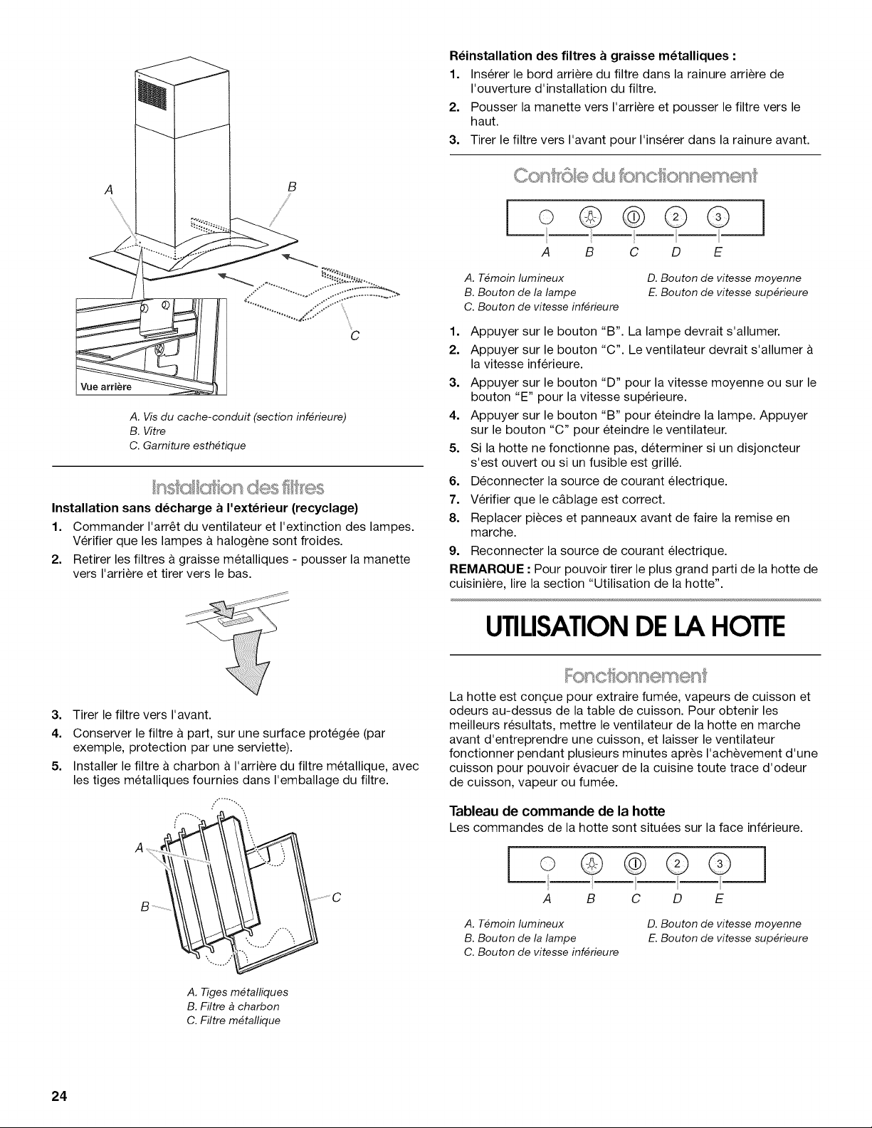
C
A. Vis du cache-conduit (section inf_rieure)
B. Vitre
C. Garniture esth_tique
n @on des
Installation sans d_charge a I'ext_rieur (recyclage)
1. Commander I'arr_t du ventilateur et I'extinction des lampes.
Verifier que les lampes a halogene sont froides.
2. Retirer les filtres a graisse m6talliques - pousser la manette
vers I'arriere et tirer vers le bas.
A. T_moin lumineux
B. Bouton de la lampe
C. Bouton de vitesse inf_rieure
1. Appuyer sur le bouton "B". La lampe devrait s'allumer.
2. Appuyer sur le bouton "C". Le ventilateur devrait s'allumer
la vitesse inferieure.
3. Appuyer sur le bouton "D" pour la vitesse moyenne ou sur le
bouton "E" pour la vitesse superieure.
4. Appuyer sur le bouton "B" pour eteindre la lampe. Appuyer
sur le bouton "C" pour eteindre le ventilateur.
5. Si la hotte ne fonctionne pas, determiner si un disjoncteur
s'est ouvert ou si un fusible est grill&
6. Deconnecter la source de courant electrique.
7. Verifier que le c&blage est correct.
8. Replacer pieces et panneaux avant de faire la remise en
marche.
9. Reconnecter la source de courant electrique.
REMARQUE • Pour pouvoir tirer le plus grand parti de la hotte de
cuisiniere, lire la section "Utilisation de la hotte".
D. Bouton de vitesse moyenne
E.Bouton de vitesse sup_rieure
UTILISATIONDELA HOTTE
3. Tirer le filtre vers I'avant.
4. Conserver le filtre a part, sur une surface protegee (par
exemple, protection par une serviette).
5. Installer le filtre & charbon & I'arriere du filtre metallique, avec
les tiges metalliques fournies dans I'emballage du filtre.
A. Tigesm_talliques
B.Filtre _ charbon
C.Filtre m_tallique
24
La hotte est congue pour extraire fumee, vapeurs de cuisson et
odeurs au-dessus de la table de cuisson. Pour obtenir les
meilleurs resultats, mettre le ventilateur de la hotte en marche
avant d'entreprendre une cuJsson, et laisser le ventilateur
fonctionner pendant plusieurs minutes apr@sI'achevement d'une
cuisson pour pouvoir evacuer de la cuisine toute trace d'odeur
de cuisson, vapeur ou fum@e.
Tableau de commande de la hotte
Les commandes de la hotte sont situ_es sur la face inferieure.
o ©@
A B C
A. T_moin lumineux
B. Bouton de la lampe
C. Bouton de vitesse inf_rieure
©@
D E
D. Bouton de vitesse moyenne
E.Bouton de vitesse sup_rieure
Page 25

Commande de la lampe
1. Appuyer sur le bouton "B" pour I'allumage.
2. Appuyer de nouveau sur le bouton "B" pour I'extinction.
ENTRETIENDELA HOTTE
Ventilateur - mise en marche et s_lection de la vitesse
1. Appuyer sur le bouton "C" pour la vitesse minimale; appuyer
sur le bouton "D" pour la vitesse moyenne; appuyer sur le
bouton "E" pour la vitesse superieure.
2. Appuyer de nouveau sur le bouton "C" pour commander
I'arr_t du ventilateur.
IMPORTANT : Nettoyer la hotte et les filtres & graisse
regulierement en suivant les instructions suivantes. Remettre en
place les filtres a graisse avant de mettre en marche la hotte.
Avant d'entreprendre le nettoyage de la hotte, verifier que les
lampes ont refroidi.
Surfaces externes
Nettoyer la hotte avec un detergent doux et un chiffon doux. Ne
pas utiliser un produit de nettoyage abrasif ou un tampon de laine
d'acier.
Filtres & graisse m_talliques
Laver frequemment les filtres. Placer les filtres metalliques dans
un lave-vaisselle ou une solution de detergent chaude. Laisser
I'eau s'ecouler a travers les trous des bords de chaque filtre et
secher parfaitement chaque filtre avant de le reinstaller.
D_pose des filtres m_talliques :
1. Commander I'arr_t du ventilateur et I'extinction des lampes.
Verifier que la lampe a halogene est froide.
2. Pousser la manette vers I'arriere et tirer vers le bas.
3. Tirer le filtre vers I'avant.
R_installation des filtres a graisse m_talliques :
1. Inserer le bord arriere du filtre dans la rainure arriere de
I'ouverture d'installation du filtre.
2. Pousser la manette vers I'arriere et pousser le filtre vers le
haut.
3. Tirer le filtre vers I'avant pour I'inserer dans la rainure avant.
Remplacement des filtres a charbon :
1. Commander I'arr_t du ventilateur et I'extinction des lampes.
Verifier que la hotte est eteinte et que la lampe a halogene est
froide.
2. Retirer les filtres a graisse metalliques - pousser la manette
vers I'arriere et tirer vers le bas.
3. Tirer le filtre vers I'avant.
4. Conserver le filtre a part, sur une surface protegee (par
exemple, protection par une serviette).
5. Enlever les fils metalliques et nettoyer ou jeter le filtre
charbon.
6. Installer le nouveau filtre a charbon (neuf ou nettoye)
I'arriere du filtre metallique, avec les fils metalliques fournis
dans I'emballage du filtre.
R_installation des filtres a graisse m_talliques :
1. Inserer le bord arriere du filtre metallique dans la rainure
arriere de I'ouverture d'installation du filtre.
2. Pousser la manette vers I'arriere et pousser le filtre vers le
haut.
3. Tirer le filtre vers I'avant et inserer lefiltre dans la rainure
avant.
Remplacement d'une lampe _ halog_ne
Interrompre I'alimentation de la hotte; attendre le refroidissement
des lampes a halogene. Remplacer I'ampoule en la manipulant
avec un mouchoir de papier ou des gants de coton. Ne pas
toucher I'ampoule avec les doigts nus.
Si les nouvelles lampes ne fonctionnent pas, verifier que chaque
lampe est correctement inseree dans sa douille avant de
demander I'intervention d'un depanneur.
1. Deconnecter la source de courant electrique.
2. A I'aide d'un tournevis a lame plate, degager doucement la
garniture de lampe.
Filtres & charbon - Installation sans d_charge _ I'ext_rieur
(recyclage)
Les filtres a charbon retiennent les composes responsables des
odeurs de cuisson. On peut nettoyer et reactiver ces filtres
charbon. Dans le contexte d'une utilisation normale (utilisation de
la hotte 2 h 30 par jour en moyenne), on doit nettoyer le filtre
intervalle de deux mois.
Nettoyer le filtre dans un lave-vaisselle avec un detergent normal
(selectionner la temperature la plus elevee). Laver le filtre
separement. Pour la reactivation du filtre, secher le filtre dans un
four pendant 10 minutes a une temperature maximum de
210°F (100°C).
On doit remplacer le filtre a charbon apres environ 3 annees
d'utilisation. Pour la commande d'un filtre a charbon neuf, voir la
section "Assistance ou service".
3. Enlever la lampe. Installer une lampe a halogene neuve de
12 V/20 W maximum, a culot de type G-4.
4. Reinstaller la garniture de lampe.
5. Reconnecter la source de courant electrique.
25
Page 26

SCHI MA DECABLAGE
_N_
Z
SWl SW2 SW3 SW4
_ampe allum_e I X X X
_ampe _teinte 0 X x X
Vel 1 x 1 0 0
Vel 2 x t 1 0
Vel 3 x 1 x 1
oDE]lID
__ SWl SW2 SW3 SW4
BE07AA
BL
SWx
[]
__........_l°_°l_°................°_ i_-3 4_-_
i
GRIS
R
BL
BU
JA
JA
@@@@
VlTESSE
DE MOTEUR
1
2
3
4
IHYB
BROCHES DE RESISTANCE (Ohms)
CONNEXION ENTRE LES BROCHES
Bleu(3)-blanc(7)
Bleu(3)-rouge(6) de 5,6 a 11,8 ohms
Bleu(3)-vert(5)
IBleu(3)-vide(4)
N
N
BU
JA
MAR
JA
26
Page 27

ASSISTANCEOU SERVICE
Lors d'un appel pour assistance ou service, veuillez connaYtre la
date d'achat, le numero de modele et le numero de serie au
complet de I'appareil. Ces renseignements nous aideront & mieux
repondre a votre demande.
Si vous avez besoin de pieces de rechange
Si vous avez besoin de commander des pieces de rechange,
nous vous recommandons d'employer uniquement des pieces
specifiees par I'usine. Les pieces specifiees par I'usine
conviendront et fonctionneront bien parce qu'elles sont
fabriquees avec la m_me precision utilisee dans la fabrication de
chaque nouvel appareil. Pour Iocaliser des pieces specifiees par
I'usine dans votre region, nous appeler ou telephoner au centre
de service designe le plus proche.
Veuillez appeler sans frais le Centre d'interaction avec la clientele
de Whirlpool Canada LP au : 1-800-807-6777.
Nos consultants vous renseigneront sur les sujets suivants •
• Caracteristiques et specifications sur toute notre gamme
d'appareils electromenagers.
• Consignes d'utilisation et d'entretien.
• Ventes d'accessoires et pieces de rechange.
• References aux marchands Iocaux, aux distributeurs de
pieces de rechange et aux compagnies de service. Les
techniciens de service designes par Whirlpool Canada LP
sont formes pour remplir la garantie des produits et fournir un
service apres la garantie, partout au Canada.
Pour plus d'assistance
Si vous avez besoin de plus d'assistance, vous pouvez
soumettre par ecrit toute question ou preoccupation & Whirlpool
Canada LP a I'adresse suivante :
Centre d'interaction avec la clientele
Whirlpool Canada LP
1901 Minnesota Court
Mississauga, Ontario L5N 3A7
Veuillez inclure dans votre correspondance un numero de
telephone oQ on peut vous joindre dans la journee.
Liste d'accessoires
Ensemble Filtre _ charbon
Piece n° 4396850
27
Page 28

GARANTIEDESGROS APPAREILSMENAGERS
WHIRLPOOLCORPORATION
GARANTIE LIMITleE DE UN AN
Pendant un an a compter de la date d'achat, Iorsque ce gros appareil menager est utilise et entretenu conformement aux instructions
jointes a ou fournies avec le produit, Whirlpool Corporation ou Whirlpool Canada LP (ci-apres designees "Whirlpool") paiera pour les
pieces specifiees par I'usine et la main-d'oeuvre pour corriger les vices de materiaux ou de fabrication. Le service doit etre fourni par
une compagnie de service designee par Whirlpool. Cette garantie limitee s'applique exclusivement Iorsque I'appareil est utilise dans le
pays oQ il a ete achet&
WHIRLPOOL NE PRENDRA PAS EN CHARGE
1. Les visites de service pour rectifier I'installation du gros appareil menager, montrer a I'utilisateur comment utiliser I'appareil,
remplacer ou reparer des fusibles ou rectifier le c&blage ou la plomberie du domicile.
2. Les visites de service pour reparer ou remplacer les ampoules electriques de I'appareil, les filtres a air ou les filtres a eau. Ces
pieces consomptibles ne sont pas couvertes par la garantie.
3. Les reparations Iorsque le gros appareil menager est utilise a des fins autres que I'usage unifamilial normal.
4. Les dommages imputables a : accident, modification, usage impropre ou abusif, incendie, inondation, actes de Dieu, installation
fautive ou installation non conforme aux codes d'electricite ou de plomberie, ou I'utilisation de produits non approuves par
Whirlpool.
5. Toute perte d'aliments due a une defaillance du refrigerateur ou du congelateur.
6. Le coot des pieces de rechange et de la main-d'ceuvre pour les appareils utilises hors des 12tats-Unis ou du Canada.
7. Le ramassage et la livraison. Ce gros appareil menager est con£;u pour etre repare & domicile.
8. Les reparations aux pieces ou systemes resultant d'une modification non autorisee faite a I'appareil.
9. Les frais de transport pour le service d'un produit dans les regions eloignees.
10. La depose et la reinstallation de votre appareil si celui-ci est installe dans un endroit inaccessible ou n'est pas installe
conformement aux instructions d'installation fournies.
11. Le coot des pieces de rechange et de la main-d'ceuvre Iorsque I'appareil est utilise dans un pays autre que le pays oQ il a ete
achet&
CLAUSE D'EXONI=RATION DE RESPONSABILITI= AU TITRE DES GARANTIES IMPLICITES; LIMITATION DES RECOURS
LE SEUL ET EXCLUSlF RECOURS DU CLIENT DANS LE CADRE DE LA PRI2SENTE GARANTIE LIMITI2E CONSlSTE EN LA
RI_PARATION PRI_VUE CI-DESS.US. LES GARANTIES IMPLICITES, Y COMPRIS LES GARANTIES APPLICABLES DE QUALITI_
MARCHANDE ET D'APTITUDE A UN USAGE PARTICULIER, SONT LIMITI_ES A UN AN OU A LA PLUS COURTE PI_RIODE AUTORISI_E
PAR LA LOI. WHIRLPOOL N'ASSUME AUCUNE RESPONSABILITI_ POUR LES DOMMAGES FORTUITS OU INDIRECTS. CERTAINES
JURIDICTIONS NE PERMETTENT PAS L'EXCLUSlON OU LA LIMITATION DES DOMMAGES FORTUITS OU INDIRECTS, OU LES
LIMITATIONS DE LA DURI2E DES GARANTIES IMPLICITES DE QUALITI 2 MARCHANDE OU D'APTITUDE A UN USAGE PARTICULIER,
DE SORTE QUE CES EXCLUSIONS OU LIMITATIONS PEUVENT NE PAS S'APPLIQUER DANS VOTRE CAS. CE-i-i-E GARANTIE VOUS
CONF#RE DES DROITS JURIDIQUES SPI2CIFIQUES ET VOUS POUVEZ 12GALEMENT JOUIR D'AUTRES DROITS QUI PEUVENT
VARIER D'UNE JURIDICTION A UNE AUTRE.
A I'exterieur du Canada et des 50 12tatsdes 12tats-Unis, cette garantie ne s'applique pas. Contacter votre marchand Whirlpool autorise
pour determiner si une autre garantie s'applique.
Si vous avez besoin de service, voir d'abord lasection "Depannage" du Guide d'utilisation et d'entretien. Apres avoir verifie la section
"Depannage", de I'aide supplementaire peut etre trouvee en verifiant la section "Assistance ou service" ou en appelant Whirlpool. Aux
E.-U., composer le 1-800-253-1301. Au Canada, composer le 1-800-807-6777. 12/05
Conservez ce manuel et votre regu de vente ensemble pour
r_f_rence ult_rieure. Pour le service sous garantie, vous
devez presenter un document prouvant la date d'achat ou
d'installation.
Inscrivez les renseignements suivants au sujet de votre gros
appareil menager pour mieux vous aider a obtenir assistance ou
service en cas de besoin. Vous devrez connaitre le numero de
modele et le numero de serie au complet. Vous trouverez ces
renseignements sur la plaque signaletique situee sur le produit.
Nom du marchand
Adresse
Numero de t_lephone
Numero de module
Numero de serie
Date d'achat
W10018010
© 2006.
All rights reserved.
Tous droits reserves.
5/06
Printed in Italy
Imprime en Italie
 Loading...