

Page 1

INSTALLATION INSTRUCTIONS
IMPORTANT:
Sa
IMPOR
À conser
.
SLIDE‑INELECTRIC RANGES
INSTRUCTIONS D’INSTALLATION
DESCUISINIÈRES ÉLECTRIQUES
ENCASTRABLES
Table of Contents/Table des matières
RANGE SAFETY .............................................................................2
INSTALLATION REQUIREMENTS .................................................3
Tools and Parts .............................................................................3
Location Requirements ................................................................3
Electrical Requirements - U.S.A. Only .........................................6
Electrical Requirements - Canada Only .......................................7
INSTALLATION INSTRUCTIONS ...................................................8
Unpack Range..............................................................................8
Install Anti-Tip Bracket .................................................................8
Adjust Leveling Legs ....................................................................9
Level Range ................................................................................10
Electrical Connection - U.S.A. Only ...........................................10
Verify Anti-Tip Bracket Is Installed and Engaged .....................15
Remove/Replace Drawer ...........................................................16
Oven Door ..................................................................................16
Complete Installation .................................................................17
SÉCURITÉ DE LA CUISINIÈRE ...................................................18
EXIGENCES D’INSTALLATION ...................................................19
Outillage et pièces ......................................................................19
Exigences d’emplacement .........................................................19
Spécifications électriques – Canada seulement .......................22
INSTRUCTIONS D’INSTALLATION .............................................23
Déballage de la cuisinière ..........................................................23
Installation de la bride antibasculement ....................................23
Réglage des pieds de nivellement .............................................24
Réglage de l’aplomb de la cuisinière .........................................25
Vérifier que la bride antibasculement
est bien installée et engagée ....................................................25
Dépose et réinstallation du tiroir ................................................26
Porte du four ..............................................................................26
Achever l’installation ..................................................................27
ve for local electrical inspector's use.
W11047691A
TANT :
ver pour consultation par l'inspecteur local des installations électriques
Page 2
RANGE SAFETY
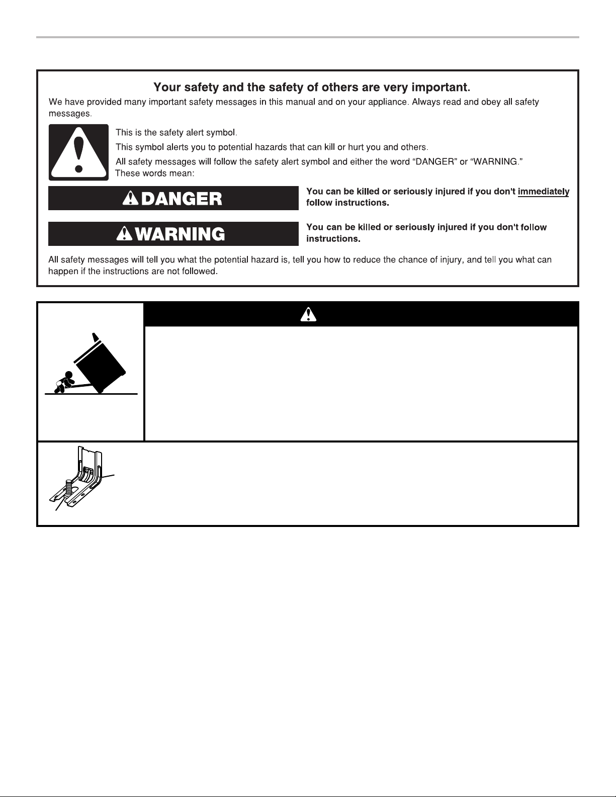
WARNING
Tip Over Hazard
A child or adult can tip the range and be killed.
Install anti-tip bracket to floor or wall per installation instructions.
Slide range back so rear range foot is engaged in the slot of the anti-tip bracket.
Re-engage anti-tip bracket if range is moved.
Do not operate range without anti-tip bracket installed and engaged.
Failure to follow these instructions can result in death or serious burns to children and adults.
Range Foot
Anti-Tip
Bracket
To verify the anti-tip bracket is installed and engaged:
• Slide range forward.
• Look for the anti-tip bracket securely attached to floor or wall.
• Slide range back so rear range foot is under anti-tip bracket.
• See installation instructions for details.
2
Page 3

INSTALLATION REQUIREMENTS
Tools and Parts
Gather the required tools and parts before starting installation.
Read and follow the instructions provided with any tools listed
here.
Tools Needed
■ Tape measure
■ Flat-blade screwdriver
■ Phillips screwdriver
■ Level
■ Hand or electric drill
■ Wrench or pliers
■ Marker or pencil
■ Masking tape
Parts Supplied
Check that all parts are included.
■ 10-32 hex nuts (attached to terminal block) (3)
■ Direct wire lugs (3)
■ #10 x 1
■ Anti-tip bracket (inside oven cavity)
■ Oven racks (2)
5
/8" (4.1 cm) screws (for mounting anti-tip bracket) (2)
Anti-tip bracket must be securely mounted to the back wall
or floor. Thickness of flooring may require longer screws to
anchor bracket to subfloor. Longer screws are available from
your local hardware store.
1
■
/4" (6.4 mm) drive ratchet
1
■
/4" (6.4 mm) nut driver
3
■
/8" (9.5 mm) and 5/16"
(8 mm) nut driver
1
■
/8" (3.2 mm) drill bit (for
wood floors)
■ Tin snips or large wire
cutters (for cutting ground
strap if necessary)
Parts Needed
If using a power supply cord kit:
■ A UL Listed power supply cord kit marked for use with
ranges. The cord should be rated at 250 volts minimum,
40 amps or 50 amps, that is marked for use with nominal
13/8" (3.5 cm) diameter connection opening and must end in
ring terminals or open-end spade terminals with upturned
ends.
■ A UL Listed strain relief.
Check local codes. Check existing electrical supply. See the
appropriate “Electrical Requirements” section.
It is recommended that all electrical connections be made by a
licensed, qualified electrical installer.
Optional Parts
To purchase these or any other accessories, please reference the
“Accessories” section of the User Guide for contact information.
■ Side Trim Kits:
5
/8" (1.7 cm) White - Order Part Number W10675027
5
/8" (1.7 cm) Black - Order Part Number W10675026
5
/8" (1.7 cm) Stainless Steel - Order Part Number W10675028
11/8" (2.9 cm) White - Order Part Number W10731885
11/8" (2.9 cm) Black - Order Part Number W10731886
11/8" (2.9 cm) Stainless Steel - Order Part Number
W10731887
■ Backsplash Kits:
High 6" (15.2 cm) White - Order Part Number W10655448
High 6" (15.2 cm) Black - Order Part Number W10655449
High 6" (15.2 cm) Stainless Steel - Order Part Number
W10655450
3
Page 4
Location Requirements
A
IMPORTANT: Observe all governing codes and ordinances.
■ It is the installer’s responsibility to comply with installation
clearances specified on the model/serial/rating plate. The
model/serial/rating plate is located behind the oven door on
the top right-hand side of the oven frame.
■ The range should be located for convenient use in the
kitchen.
■ Recessed installations must provide complete enclosure of
the sides and rear of the range.
■ All openings in the wall or floor where range is to be installed
must be sealed.
■ Cabinet opening dimensions that are shown must be used.
Given dimensions are minimum clearances.
■ The anti-tip bracket must be installed. To install the anti-tip
bracket shipped with the range, see the “Install Anti-Tip
Bracket” section.
■ Grounded electrical supply is required. See the appropriate
“Electrical Requirements” section.
■ Contact a qualified floor covering installer to check that the
floor covering can withstand at least 200°F (93°C).
■ Use an insulated pad or
installing range over carpeting.
IMPORTANT: To avoid damage to your cabinets, check with
your builder or cabinet supplier to make sure that the materials
used will not discolor, delaminate, or sustain other damage. This
oven has been designed in accordance with the requirements
of UL and CSA International and complies with the maximum
allowable wood cabinet temperatures of 194°F (90°C).
Mobile Home - Additional Installation Requirements
The installation of this range must conform to the Manufactured
Home Construction and Safety Standard, Title 24 CFR,
Part 3280 (formerly the Federal Standard for Mobile Home
Construction and Safety, Title 24, HUD Part 280). When such
standard is not applicable, use the Standard for Manufactured
Home Installations, ANSI A225.1/NFPA 501A or local codes.
In Canada, the installation of this range must conform with the
current standards CAN/CSA-A240-latest edition, or local codes.
Mobile Home Installations Require:
■ When this range is installed in a mobile home, it must be
secured to the floor during transit. Any method of securing
the range is adequate as long as it conforms to the
standards listed above.
■ Four-wire power supply cord or cable must be used in a
mobile home installation.
1
/4" (0.64 cm) plywood under range if
Product Dimensions
This manual covers several models. Your model may appear
different from the models depicted. Dimensions given are
maximum dimensions across all models.
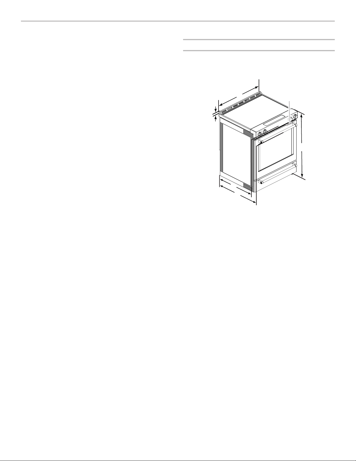
Model KSEB900E
B
E
F
A. 1³/16" (3.0 cm) height from
cooktop to top of vent
7
B. 29
/8" (75.9 cm)
C. Model/serial/rating plate
(located behind the oven door
on the top right-hand side of
the oven frame)
D. 36" (91.4 cm) height to top of
cooktop edge with leveling
legs screwed in all the way*
E. 28
from front of console to back
of range
F. 28
from handle to back of range
IMPORTANT: Range must be level after installation. Follow the
instructions in the “Level Range” section. Using the cooktop as a
reference for leveling the range is not recommended.
* Range can be raised approximately 1" (2.5 cm) by adjusting
the leveling legs.
C
D
5
/16" (71.9 cm) max. depth
7
/8" (73.3 cm) max. depth
4
Page 5
Cabinet Dimensions
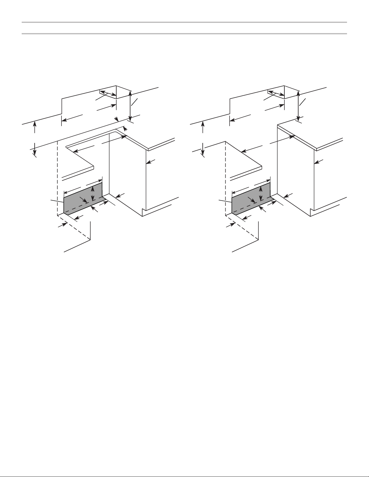
Cabinet opening dimensions shown are for 25" (64.0 cm) countertop depth, 24" (61.0 cm) base cabinet depth and 36" (91.4 cm)
countertop height.
IMPORTANT: If installing a range hood or microwave hood combination above the range, follow the range hood or microwave hood
combination installation instructions for dimensional clearances above the cooktop surface.
Range may be installed next to combustible walls with zero clearance.
NOTE: When installed in a slide-in cutout, the front of oven door may protrude beyond the base cabinet.
Slide-In Cutout Freestanding Cutout
D
B
C
B
C
D
L
A
E
K
G
H
I
F
J
I
A. 18" (45.7 cm) upper side cabinet to countertop
B. 13" (33 cm) max. upper cabinet depth
C. 30" (76.2 cm) min. opening width
D. For minimum clearance to top of cooktop, see NOTE*.
E. 30" (76.2 cm) min. opening width
F. The shaded area is recommended for installation of grounded
outlet.
1
G. 13
/8" (33.3 cm)
11
H. 7
/16" (19.5 cm)
13
I. 4
/16" (12.2 cm)
11
J. 3
/16" (9.4 cm) plus measurement of L
K. Cabinet door or hinges should not extend into the cutout.
L. Remaining counter depth should not exceed 2
1
/4" (5.7 cm).
A
E
K
G
H
I
F
J
I
A. 18" (45.7 cm) upper side cabinet to countertop
B. 13" (33 cm) max. upper cabinet depth
C. 30" (76.2 cm) min. opening width
D. For minimum clearance to top of cooktop, see NOTE*.
E. 30" (76.2 cm) min. opening width
F. The shaded area is recommended for installation of grounded
outlet.
1
G. 13
/8" (33.3 cm)
11
H. 7
/16" (19.5 cm)
13
I. 4
/16" (12.2 cm)
11
J. 3
/16" (9.4 cm)
K. Cabinet door or hinges should not extend into the cutout.
* NOTE: 24" (61.0 cm) minimum when bottom of wood or metal cabinet is shielded by not less than 1/4" (0.64 cm) flame retar-
dant millboard covered with not less than No. 28 MSG sheet steel, 0.015" (0.4 mm) stainless steel, 0.024" (0.6 mm) aluminum or
0.020" (0.5 mm) copper.
30" (76.2 cm) minimum clearance between the top of the cooking platform and the bottom of an uncovered wood or metal cabinet.
5
Page 6
Electrical Requirements ‑ U.S.A. Only
If codes permit and a separate ground wire is used, it is
recommended that a qualified electrical installer determine that
the ground path and wire gauge are in accordance with local
codes.
Do not use an extension cord.
Be sure that the electrical connection and wire size are adequate
and in conformance with the National Electrical Code, ANSI/
NFPA 70-latest edition and all local codes and ordinances.
A copy of the above code standards can be obtained from:
National Fire Protection Association
WARNING: Improper connection of the equipment-grounding
conductor can result in a risk of electric shock. Check with a
qualified electrician or service technician if you are in doubt as to
whether the appliance is properly grounded. Do not modify the
power supply cord plug. If it will not fit the outlet, have a proper
outlet installed by a qualified electrician.
Electrical Connection
To properly install your range, you must determine the type of
electrical connection you will be using and follow the instructions
provided for it here.
■ Range must be connected to the proper electrical voltage
and frequency as specified on the model/serial/rating plate.
The model/serial/rating plate is located behind the oven door
on the top right-hand side of the oven frame.
■ This range is manufactured with the neutral terminal
connected to the cabinet. Use a 3-wire, UL Listed, 40- or
50-amp power supply cord (pigtail). See the following Range
Rating chart. If local codes do not permit ground through the
neutral, use a 4-wire power supply cord rated at 250 volts,
40- or 50-amps and investigated for use with ranges.
Range Rating*
120/240 Volts 120/208 Volts Amps
8.8 - 16.5 KW 7.8 - 12.5 KW 40 or 50**
16.6 - 22.5 KW 12.6 - 18.5 KW 50
* The NEC calculated load is less than the total connected load
listed on the model/serial/rating plate.
** If connecting to a 50-amp circuit, use a 50-amp rated cord
with kit. For 50-amp rated cord kits, use kits that specify use
with a nominal 13/8" (3.5 cm) diameter connection opening.
■ A circuit breaker is recommended.
■ The range can be connected directly to the circuit breaker
box (or fused disconnect) through flexible or nonmetallic
sheathed, copper or aluminum cable. See the “Electrical
Connection - U.S.A. Only” section.
■ Allow at least 6 ft (1.8 m) of slack in the line so that the range
can be moved if servicing is ever necessary.
■ A UL Listed conduit connector must be provided at each end
of the power supply cable (at the range and at the junction
box).
■ Wire sizes and connections must conform with the rating of
the range.
■ The tech sheet and wiring diagram are located on the back
of the range in a plastic bag.
If Connecting to a 3-Wire System:
1 Batterymarch Park
Quincy, MA 02169-7471
Specified Rating of
Power Supply Cord Kit
and Circuit Protection
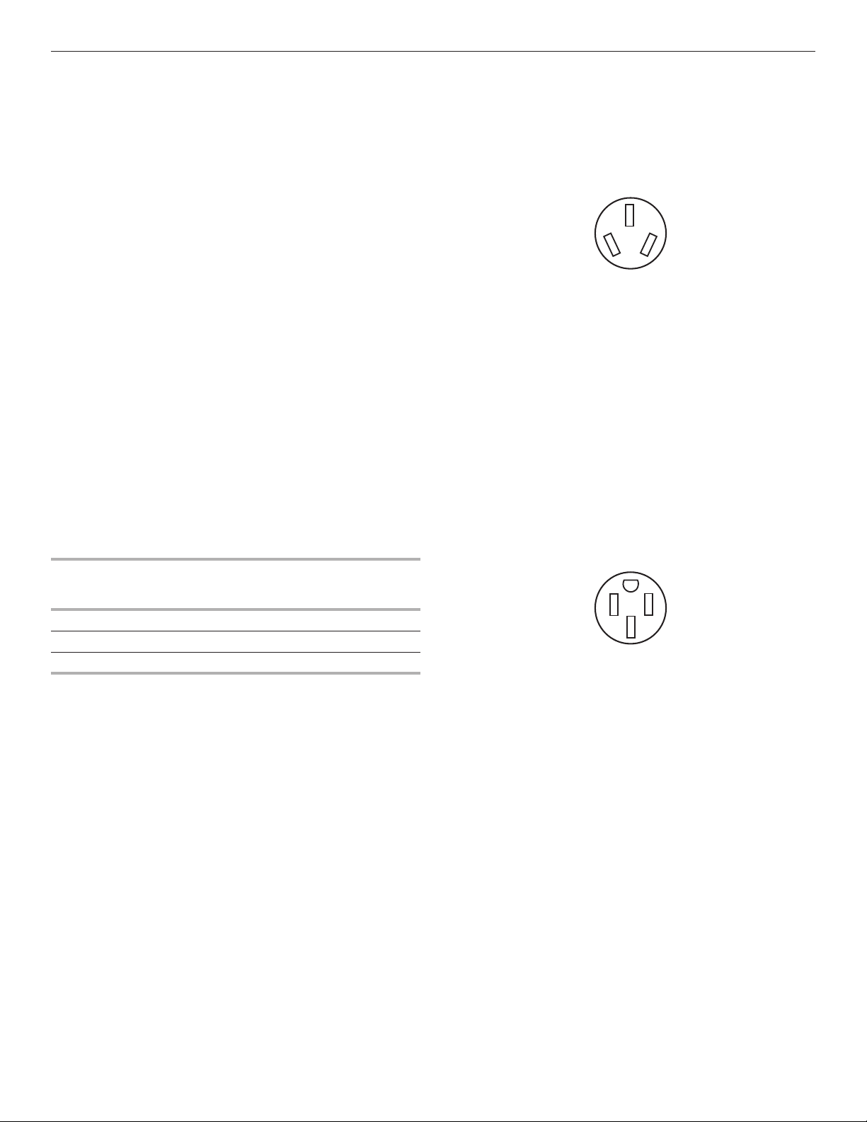
Local codes may permit the use of a UL Listed, 3-wire, 250-volt,
40- or 50-amp range power supply cord (pigtail). This cord
contains 3 copper conductors with ring terminals or open-end
spade terminals with upturned ends, terminating in a NEMA Type
10-50P plug on the supply end. Connectors on the appliance
end must be provided at the point the power supply cord enters
the appliance. This uses a 3-wire receptacle of NEMA Type
10-50R.
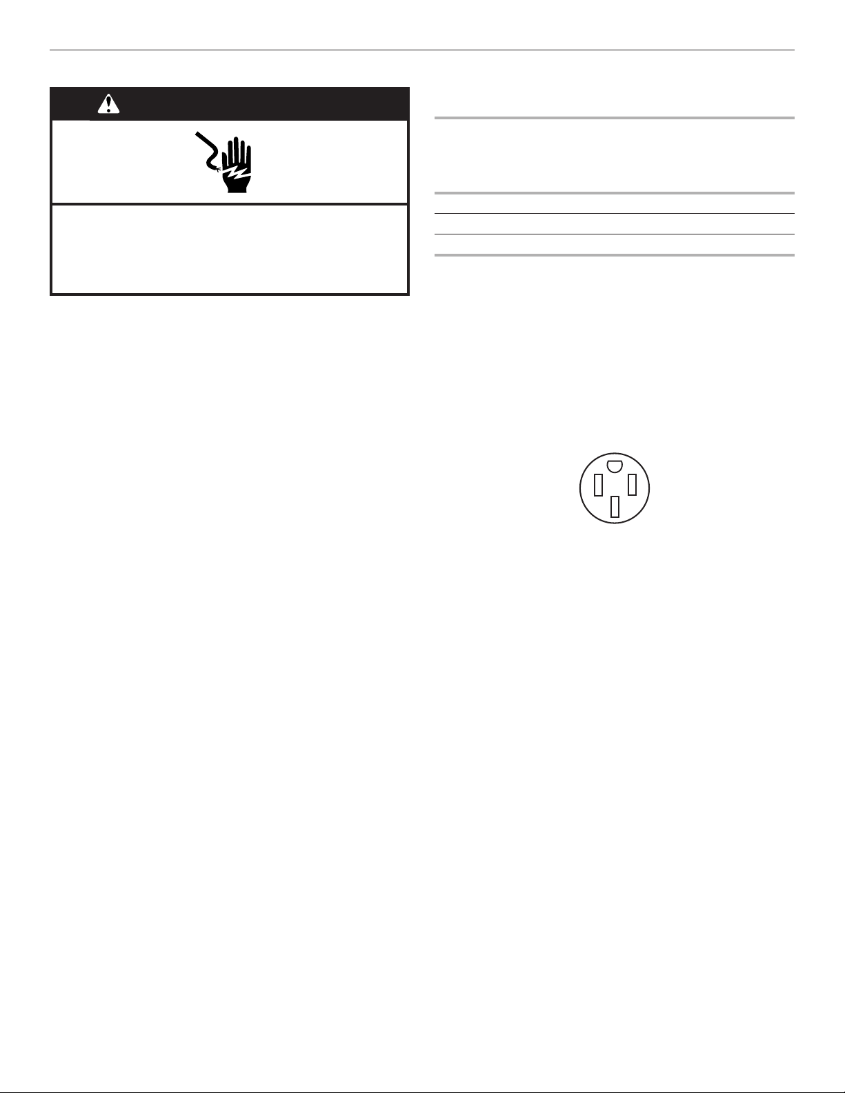
3-wire receptacle (10-50R)
If Connecting to a 4-Wire System:
This range is manufactured with the ground connected to the
neutral by a link. The ground must be revised so the green
ground wire of the 4-wire power supply cord is connected to the
cabinet. See the “Electrical Connection - U.S.A. Only” section.
Grounding through the neutral conductor is prohibited for new
branch-circuit installations (1996 NEC), mobile homes, and
recreational vehicles, or an area where local codes prohibit
grounding through the neutral conductor.
When a 4-wire receptacle of NEMA Type 14-50R is used, a
matching UL Listed, 4-wire, 250-volt, 40- or 50-amp, range
power supply cord (pigtail) must be used. This cord contains
4 copper conductors with ring terminals or open-end spade
terminals with upturned ends, terminating in a NEMA Type
14-50P plug on the supply end.
The fourth (grounding) conductor must be identified by a green
or green/yellow cover and the neutral conductor by a white
cover. Cord should be Type SRD or SRDT with a UL Listed strain
relief and be at least 4 ft (1.22 m) long.
4-wire receptacle (14-50R)
The minimum conductor sized for the copper 4-wire power
cord are:
40-amp circuit
2 No.-8 conductors
1 No.-10 white neutral
1 No.-10 green grounding
6
Page 7
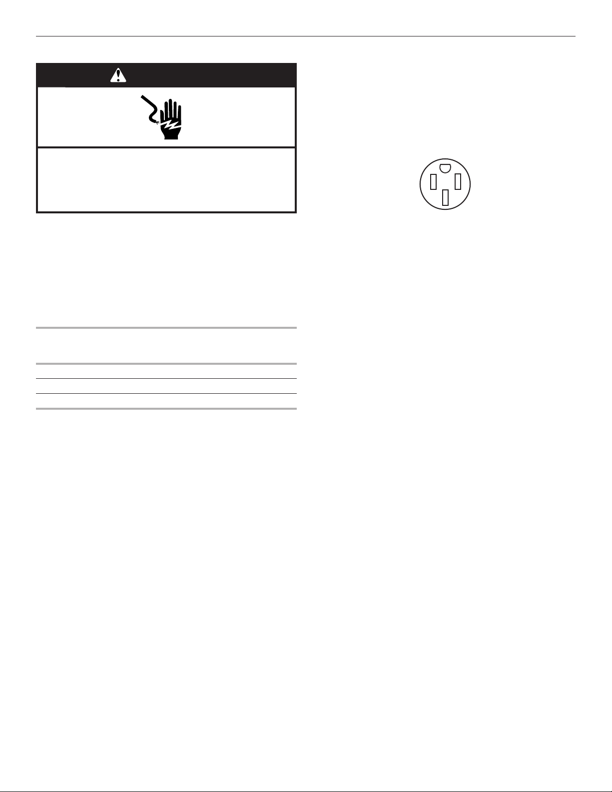
Electrical Requirements ‑ Canada Only
WARNING
Electrical Shock Hazard
Electrically ground range.
Failure to do so can result in death, fire, or
electrical shock.
■ When a 4-wire, single phase 250 volt, 60 Hz., AC only
electrical supply is available, a 40-amp minimum circuit
protection is required on 30" (76.2 cm) ranges, fused on
both sides of the line.
■ A time-delay fuse or circuit breaker is recommended.
■ This range is equipped with a UL or CSA International
Certified Power Cord intended to be plugged into a standard
14-50R wall receptacle. Be sure the wall receptacle is within
reach of range’s final location.
Be sure that the electrical connection and wire size are adequate
and in conformance with CSA Standard C22.1, Canadian
Electrical Code, Part 1 - latest edition, and all local codes
and ordinances.
A copy of the above code standards can be obtained from:
Canadian Standards Association
178 Rexdale Blvd.
Toronto, ON M9W 1R3 CANADA
■ Check with a qualified electrical installer if you are not sure
the range is properly grounded.
Range Rating*
120/240 Volts 120/208 Volts Amps
8.8 - 16.5 KW 7.8 - 12.5 KW 40 or 50**
16.6 - 22.5 KW 12.6 - 18.5 KW 50
* The NEC calculated load is less than the total connected load
listed on the model/serial/rating plate.
** If connecting to a 50-amp circuit, use a 50-amp rated cord
with kit. For 50-amp rated cord kits, use kits that specify use
with a nominal 13/8" (34.9 mm) diameter connection opening.
Specified Rating of
Power Supply Cord Kit
and Circuit Protection
■ Do not use an extension cord.
■ The wiring diagram is located on the back of the range or in
a clear plastic bag.
7
Page 8
INSTALLATION INSTRUCTIONS
Unpack Range
WARNING
Excessive Weight Hazard
Use two or more people to move and install range.
Failure to do so can result in back or other injury.
1. Remove shipping materials, tape and film from the range.
Keep cardboard bottom under range. Do not dispose of
anything until the installation is complete.
2. Remove oven racks and parts package from oven and
shipping materials.
3. To remove cardboard bottom, first take 4 cardboard
corners from the carton. Stack one cardboard corner on
top of another. Repeat with the other 2 corners. Place them
lengthwise on the floor behind the range to support the
range when it is laid on its back.
4. Using 2 or more people, firmly grasp the range and gently lay
it on its back on the cardboard corners.
5. Remove cardboard bottom.
The leveling legs can be adjusted while the range is on its back.
See the “Adjust Leveling Legs” section.
NOTE: To place range back up into a standing position, put a
sheet of cardboard or hardboard on the floor in front of range to
protect the flooring. Using 2 or more people, stand range back
up onto the cardboard or hardboard.
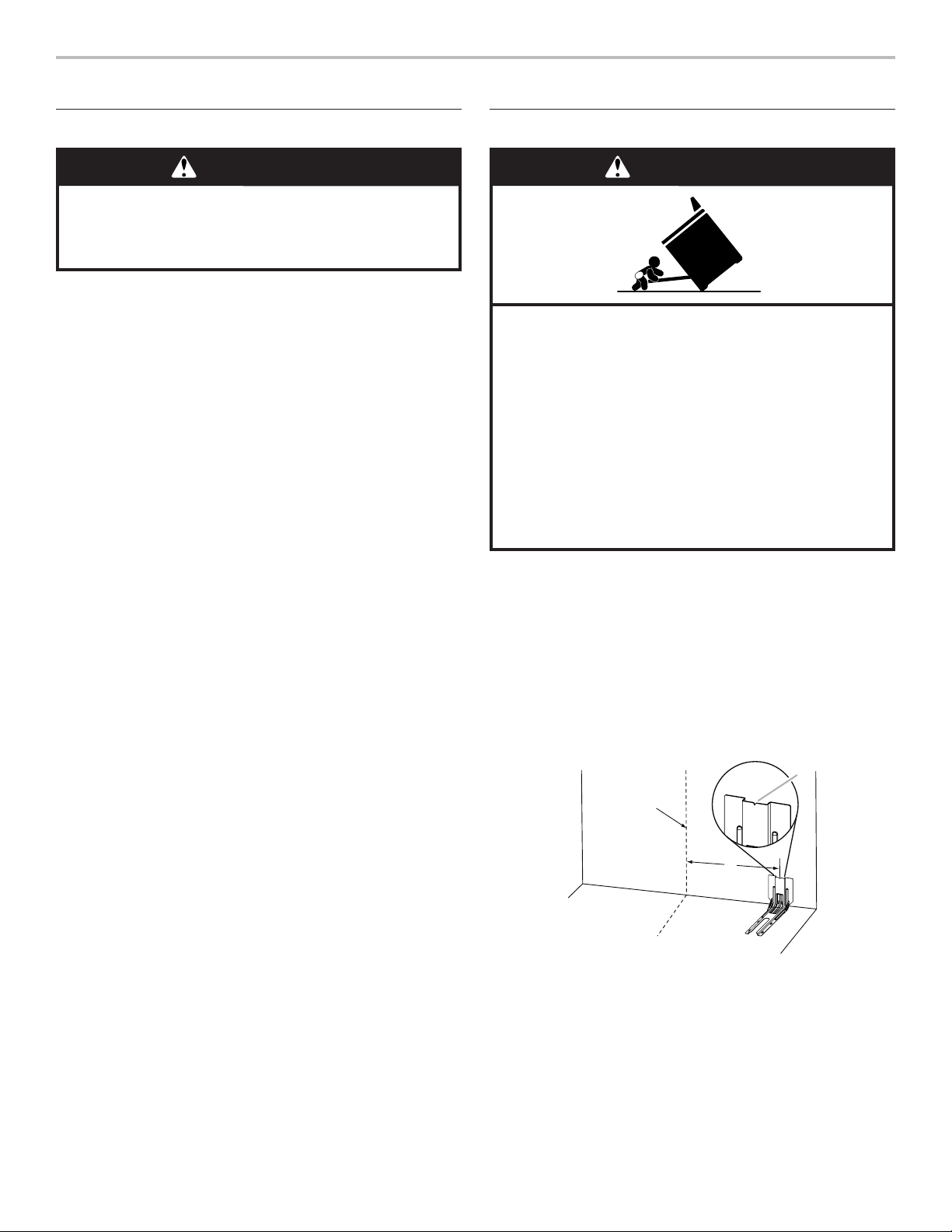
Install Anti‑Tip Bracket
WARNING
Tip Over Hazard
A child or adult can tip the range and be killed.
Install anti-tip bracket to floor or wall per installation
instructions.
Slide range back so rear range foot is engaged in the
slot of the anti-tip bracket.
Re-engage anti-tip bracket if range is moved.
Do not operate range without anti-tip bracket installed
and engaged.
Failure to follow these instructions can result in death
or serious burns to children and adults.
1. Remove the anti-tip bracket from the inside of the oven.
2. Determine which mounting method to use: floor or wall.
If you have a stone or masonry floor, you can use the wall
mounting method. If you are installing the range in a mobile
home, you must secure the range to the floor.
This anti-tip bracket and screws can be used with wood or
metal studs.
3. Determine and mark centerline of the cutout space. The
mounting bracket can be installed on either the left-hand or
right-hand side of the cutout. Position mounting bracket
against the wall in the cutout so that the V-notch of the
bracket is 121/2" (31.8 cm) from centerline, as shown.
B
Centerline
A
A. 121/2" (31.8 cm)
B. Bracket V-notch
8
Page 9
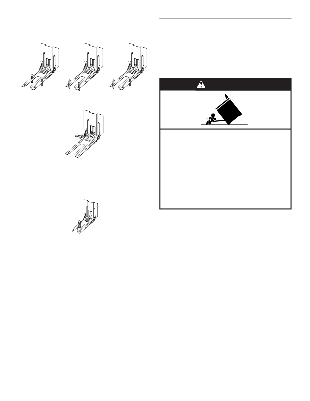
4. Drill two 1/8" (3 mm) holes that correspond to the bracket
holes of the determined mounting method. See the following
illustrations.
Floor Mounting
Rear position Front position Diagonal (2 options)
Wall Mounting
5. Using the two #10 x 15/8" (4.1 cm) Phillips-head screws
provided, mount anti-tip bracket to the wall or floor.
6. Move range close enough to opening to allow for final
electrical connections. Remove shipping base, cardboard or
hardboard from under range.
7. Move range into its final location, making sure rear leveling
leg slides into anti-tip bracket.
Adjust Leveling Legs
1. If range height adjustment is necessary, use a wrench or
pliers to loosen the 4 leveling legs.
This may be done with the range on its back or with the
range supported on 2 legs after the range has been placed
back to a standing position.
NOTE: To place range back up into a standing position, put
a sheet of cardboard or hardboard in front of range. Using 2
or more people, stand range back up onto the cardboard or
hardboard.
WARNING
Tip Over Hazard
A child or adult can tip the range and be killed.
Install anti-tip bracket to floor or wall per installation
instructions.
Slide range back so rear range foot is engaged in the
slot of the anti-tip bracket.
Re-engage anti-tip bracket if range is moved.
Do not operate range without anti-tip bracket installed
and engaged.
Failure to follow these instructions can result in death
or serious burns to children and adults.
8. Move range forward onto shipping base, cardboard or
hardboard to continue installing the range, using the
following installation instructions.
2. Measure the distance from the top of the counter to the floor.
3. Measure the distance from the top of the cooktop to the
bottom of the leveling legs. This distance should be the
same. If it is not, adjust the leveling legs to the correct
height. The leveling legs can be loosened to add up to
a maximum of 1" (2.5 cm). A minimum of 3/16" (5 mm) is
needed to engage the anti-tip bracket.
NOTE: If height adjustment is made when range is standing,
tilt the range back to adjust the front legs, and then tilt
forward to adjust the rear legs.
4. When the range is at the correct height, check that there is
adequate clearance under the range for the anti-tip bracket.
Before sliding range into its final location, check that the
antitip bracket will slide under the range and onto the rear
leveling leg prior to anti-tip bracket installation.
NOTE: If a Trim Kit will be used, the top of the cooktop
should be higher than the counter. See the Installation
Instructions included with the Trim Kit for the correct height.
9
Page 10
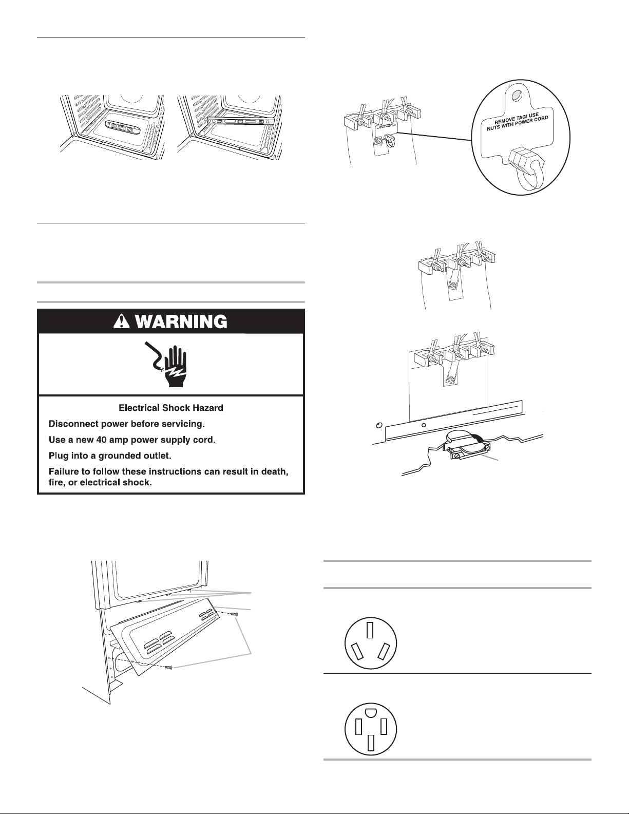
Level Range
A
B
C
1. Place level on the oven bottom, as indicated in one of the 2
figures below, depending on the size of the level. Check with
the level side to side and front to back.
2. If range is not level, use a wrench or pliers to adjust leveling
legs up or down until the range is level.
NOTE: Range must be level for satisfactory baking
performance and best cleaning results using AquaLift®
Self-Clean Technology.
Electrical Connection ‑ U.S.A. Only
If your home has a 3- or 4-wire receptacle, continue with “Install
Using a Power Supply Cord.” If your home has a 3- or 4-wire
direct connection, go to “Install Using Direct Wire.”
Install Using a Power Supply Cord
3. Depending on your model, remove plastic tag holding three
10-32 hex nuts from the middle post of the terminal block.
Remove the top 10-32 hex nut from each of the 3 terminal
blocks and set aside.
OR
Remove the top 10-32 hex nut from each of the 3 terminal
blocks and set aside.
4. Assemble a UL Listed strain relief in the opening.
Power Supply Cord Strain Relief
1. Disconnect power.
2. Remove the lower access cover screws located on the back
of the range. Pull the bottom of the cover toward you and out
to remove cover from range.
A. Mounting tabs (3)
B. Lower access cover
C. Screws (2)
A
A. UL Listed strain relief
5. Complete installation following instructions for your type of
electrical connection:
4-wire (recommended)
3-wire (if 4-wire is not available)
Electrical Connection Options
If your home has:
3-wire receptacle
(NEMA type 10-50R)
4-wire receptacle
(NEMA type 14-50R)
And you will be
connecting to:
A UL Listed,
250-volt minimum,
40- or 50-amp,
range power supply
cord
A UL Listed,
250-volt minimum,
40- or 50-amp,
range power supply
cord
Go to section:
3-Wire
Connection:
Power Supply
Cord
4-Wire
Connection:
Power Supply
Cord
10
Page 11
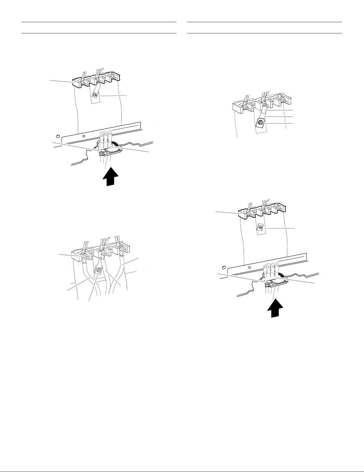
3-Wire Connection: Power Supply Cord
A
D
A
C
E
A
B
C
A
D
4-Wire Connection: Power Supply Cord
Use this method only if local codes permit connecting chassis
ground conductor to neutral wire of power supply cord.
1. Feed the power supply cord through the strain relief on the
cord/conduit plate on bottom of range. Allow enough slack
to easily attach the wiring to the terminal block.
B
C
A. Terminal block
B. Ground-link screw
C. UL Listed strain relief
D. Power supply cord wires - large opening
2. Use a 3/8" (1.0 cm) nut driver to connect the neutral (white)
wire to the center terminal block post with one of the 10-32
hex nuts.
Use this method for:
■ New branch-circuit installations (1996 NEC)
■ Mobile homes
■ Recreational vehicles
■ In an area where local codes prohibit grounding through the
neutral
1. Cut out and remove part of metal ground strap, as shown.
A Metal ground strap
B. Discard
C. Ground-link screw
2. Use a Phillips screwdriver to remove the ground-link screw
from the back of the range. Save the ground-link screw and
the end of the ground link under the screw.
3. Feed the power supply cord through the strain relief on the
cord/conduit plate on bottom of range. Allow enough slack
to easily attach the wiring to the terminal block.
B
C
B
A. 10-32 hex nut
B. Line 2 (red) wire
C. Ground-link screw
D. Neutral (white) wire
E. Line 1 (black) wire
D
A. Terminal block
B. Ground-link screw
C. UL Listed strain relief
D. Power supply cord wires
3. Connect line 2 (red) and line 1 (black) wires to the outer
terminal block posts with 10-32 hex nuts.
4. Firmly tighten hex nuts.
NOTE: For power supply cord replacement, use only a
power cord rated at 250 volts minimum, 40- or 50-amps,
that is marked for use with nominal 13/8" (3.5 cm) diameter
connection opening, with ring terminals and marked for use
with ranges.
5. Tighten strain relief screws.
IMPORTANT: Verify the tightness of the hex nuts.
6. Replace lower access cover.
11
Page 12
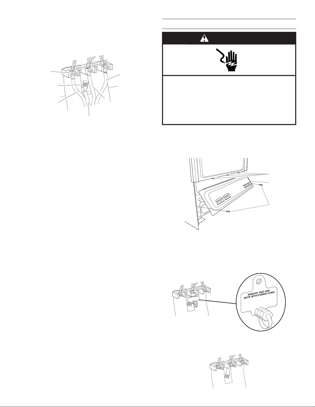
4. Use a Phillips screwdriver to connect the green ground wire
A
F
D
A
B
C
from the power supply cord to the range with the groundlink screw and ground-link section. The ground wire must be
attached over the ground-link section.
5. Use 3/8" (1.0 cm) nut driver to connect the neutral (white) wire
to the center terminal block post with one of the 10-32
hex nuts.
Install Using Direct Wire
WARNING
B
C
A. 10-32 hex nut
B. Ground-link screw
C. Line 2 (red) wire
6. Connect line 2 (red) and line 1 (black) wires to the outer
terminal block posts with 10-32 hex nuts.
7. Firmly tighten hex nuts.
NOTE: For power supply cord replacement, use only a
power cord rated at 250 volts minimum, 40- or 50-amps,
that is marked for use with nominal 13/8" (3.5 cm) diameter
connection opening, with ring terminals and marked for use
with ranges.
8. Tighten strain relief screws.
IMPORTANT: Verify the tightness of the hex nuts.
9. Replace lower access cover.
D. Green ground wire
E. Neutral (white) wire
F. Line 1 (black) wire
E
Electrical Shock Hazard
Disconnect power before servicing.
Use 8 gauge copper or 6 gauge aluminum wire.
Electrically ground range.
Failure to follow these instructions can result in death,
fire, or electrical shock.
Direct Wire Strain Relief
1. Disconnect power.
2. Remove the lower access cover screws located on the back
of the range. Pull the bottom of the cover toward you and out
to remove cover from range.
A. Mounting tabs (3)
B. Lower access cover
C. Screws (2)
3. Depending on your model, remove plastic tag holding three
10-32 hex nuts from the middle post of the terminal block.
Remove the top 10-32 hex nut from each of the 3 terminal
blocks and set aside.
OR
Remove the top 10-32 hex nut from each of the 3 terminal
blocks and set aside.
12
Page 13
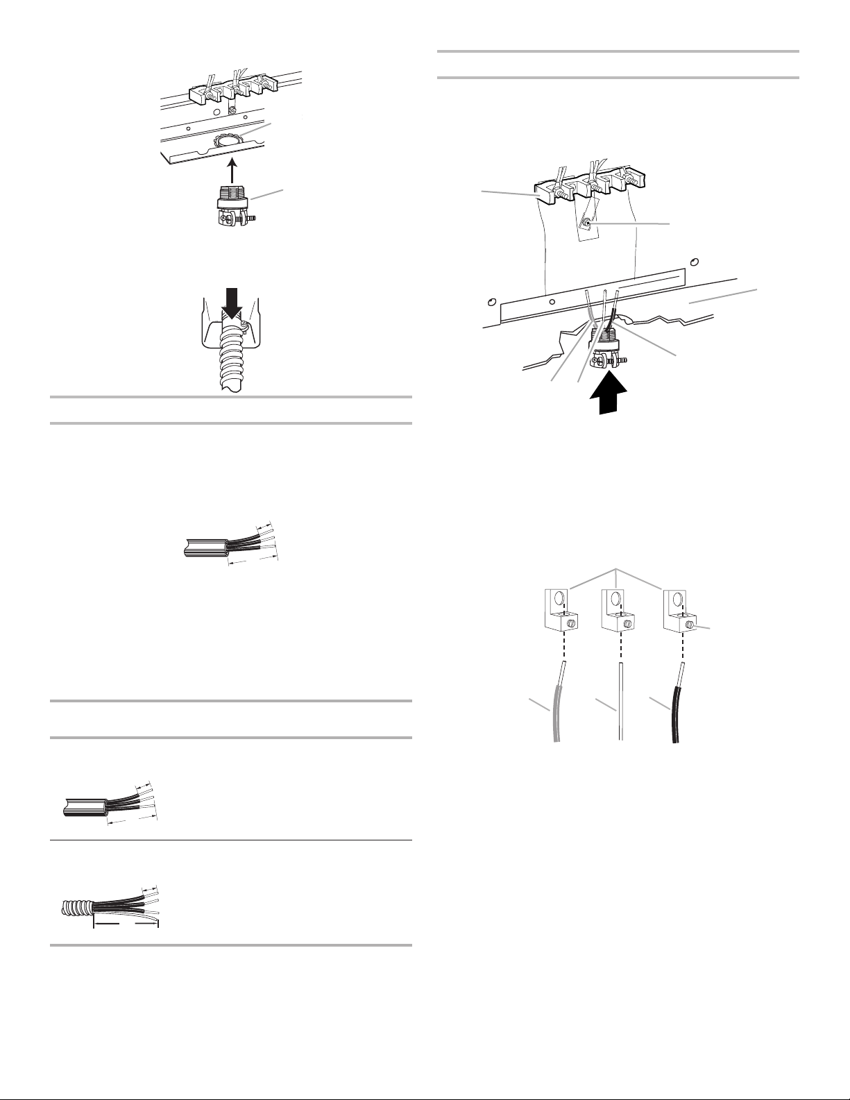
4. Assemble a UL Listed conduit connector in the opening.
(7.6 cm)
"
(12.7 cm)
"
(7.6 cm)
"
A
C
A
B
C
A
B
A. Removable retaining nut
B. Conduit
5. Tighten strain relief screw against the flexible conduit.
Direct Wire Installation: Copper or Aluminum Wire
This range may be connected directly to the fuse disconnect or
circuit breaker box. Depending on your electrical supply, make
the required 3-wire or 4-wire connection.
1. Strip outer covering back 3" (7.6 cm) to expose wires. Strip
the insulation back 3/8" (1.0 cm) from the end of each wire.
³⁄₈
(1.0 cm)
3"
3-Wire Connection: Direct Wire
Use this method only if local codes permit connecting ground
conductor to neutral supply wire.
1. Pull the wires through the conduit on cord/conduit plate on
bottom of range. Allow enough slack to easily attach the
wiring to the terminal block.
B
F
D
E
A. Terminal block
B. Ground-link screw
C. Cord/conduit plate
2. Attach terminal lugs to line 2 (red), bare (green) ground, and
line 1 (black) wires. Loosen (do not remove) the setscrew on
the front of the terminal lug and insert exposed wire end
through bottom of terminal lugs. Securely tighten setscrew to
torque as shown in the following Bare Wire Torque
Specifications chart.
D. Line 2 (red) wire
E. Bare (green) ground wire
F. Line 1 (black) wire
2. Allow enough slack in the wire to easily attach the wiring
terminal block.
3. Complete installation following instructions for your type of
electrical connection:
4-wire (recommended)
3-wire (if 4-wire is not available)
Electrical Connection Options
If your home has:
3-wire direct A circuit breaker
³⁄₈
(1.0 cm)
3"
4-wire direct A circuit breaker
³⁄₈
(1.0 cm)
5"
And you will be
connecting to:
box or fused
disconnect
box or fused
disconnect
Go to section:
3-Wire Connection:
Direct Wire
4-Wire Connection:
Direct Wire
DE
A. Terminal lug
B. Setscrew
C. Line 2 (red) wire
D. Bare (green) ground wire
E. Line 1 (black) wire
13
Page 14
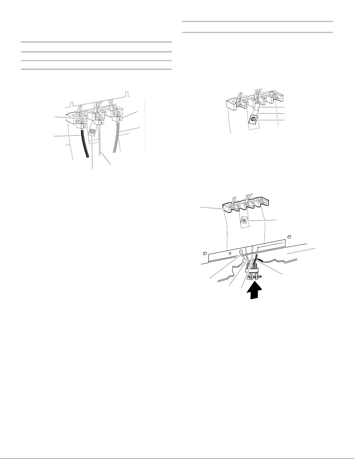
Bare Wire Torque Specifications
B
E
A
B
C
A
C
Attaching terminal lugs to the terminal block - 20 lbs-in.
(2.3 N-m)
Wire Awg Torque
8 gauge copper 25 lbs-in. (2.8 N-m)
6 gauge aluminum 35 lbs-in. (4.0 N-m)
3. Use 3/8" (1.0 cm) nut driver to connect the bare (green)
ground wire to the center terminal block post with one of the
10-32 hex nuts.
4-Wire Connection: Direct Wire
Use this method for:
■ New branch-circuit installations (1996 NEC)
■ Mobile homes
■ Recreational vehicles
■ In an area where local codes prohibit grounding through the
neutral
1. Cut out and remove part of metal ground strap, as shown.
A
F
D
A. 10-32 hex nut
B. Line 2 (red) wire
C. Ground-link screw
D. Bare (green) ground wire
E. Line 1 (black) wire
F. Terminal lug
4. Connect line 2 (red) and line 1 (black) wires to the outer
terminal block posts with 10-32 hex nuts.
5. Firmly tighten hex nuts.
IMPORTANT: Verify the tightness of the hex nuts.
6. Replace lower access cover.
A. Metal ground strap
B. Discard
C. Ground-link screw
2. Use a Phillips screwdriver to remove the ground-link screw
from the back of the range. Save the ground-link screw and
the end of the ground link under the screw.
3. Pull the wires through the strain relief on bottom of range.
Allow enough slack to easily attach wiring to the terminal
block.
B
D
E
F
G
A. Terminal block
B. Ground-link screw
C. Cord/conduit plate
D. Bare (green) ground wire
E. Line 2 (red) wire
F. Neutral (white) wire
G. Line 1 (black) wire
14
Page 15
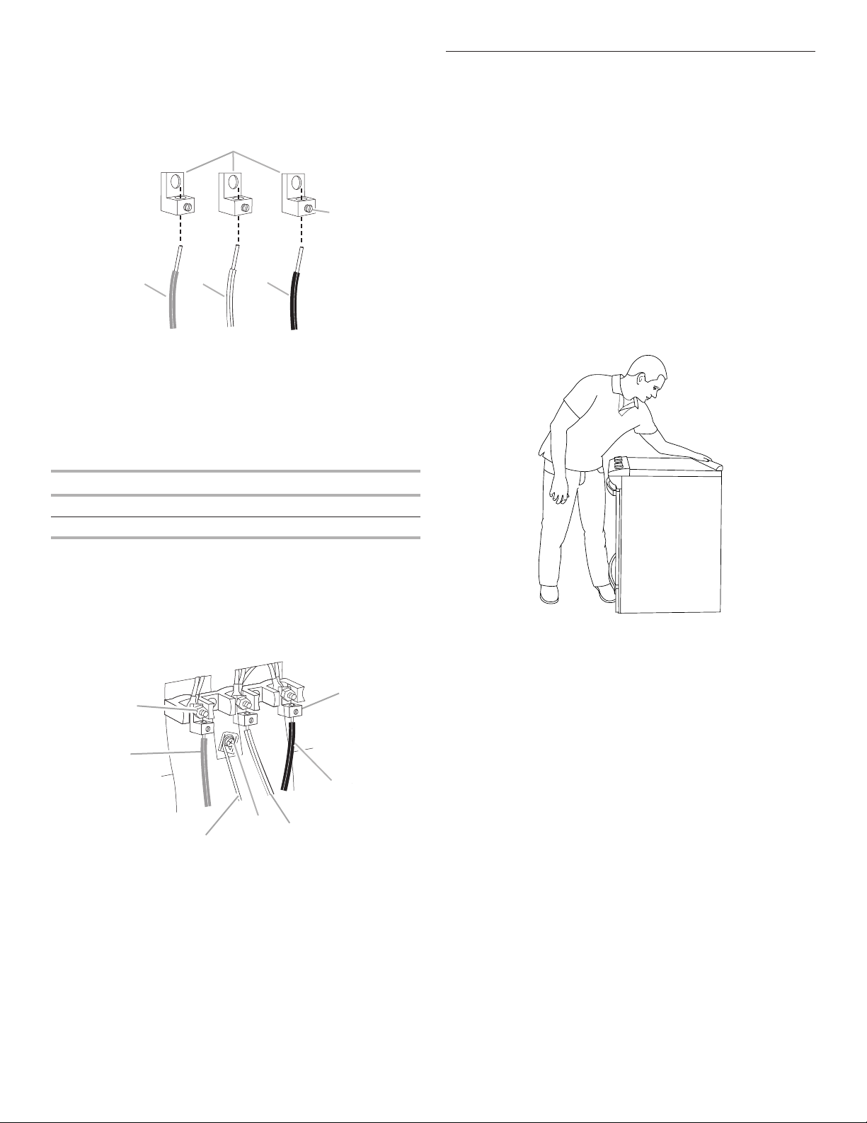
4. Attach terminal lugs to line 1 (black), neutral (white), and line
A
B
C
B
G
C
2 (red) wires. Loosen (do not remove) the setscrew on the
front of the terminal lug and insert exposed wire end through
bottom of terminal lugs. Securely tighten setscrew to torque
as shown in the following Bare Wire Torque Specifications
chart.
DE
A. Terminal lug
B. Setscrew
C. Line 2 (red) wire
D. Neutral (white) wire
E. Line 1 (black) wire
Bare Wire Torque Specifications
Attaching terminal lugs to the terminal block - 20 lbs-in.
(2.3 N-m)
Verify Anti‑Tip Bracket Is Installed
andEngaged
On Ranges Equipped with a Premium Storage Drawer:
1. Slide range into final location, making sure rear leveling leg
slides into anti-tip bracket.
2. Remove the premium storage drawer. See the “Remove/
Replace Drawer” section.
3. Use a flashlight to look underneath the bottom of the range.
4. Visually check that the rear range foot is inserted into the slot
of the anti-tip bracket.
On Ranges Equipped with a Warming Drawer or
Baking Drawer:
1. Slide range into final location, making sure rear leveling leg
slides into anti-tip bracket. Leave a 1" (2.5 cm) gap between
the back of the range and the back wall.
2. Place the outside of your foot against the bottom front of the
warming drawer or baking drawer to keep the range from
moving, and then grasp the back of the range, as shown.
Wire Awg Torque
8 gauge copper 25 lbs-in. (2.8 N-m)
6 gauge aluminum 35 lbs-in. (4.0 N-m)
5. Use a hex or Phillips screwdriver to connect the bare (green)
ground wire to the range with the ground-link screw and
ground-link section. The ground wire must be attached over
the ground-link section and must not contact any other
terminal.
6. Use 3/8" (1.0 cm) nut driver to connect the neutral (white) wire
to the center terminal block post with one of the 10-32 hex
nuts.
A
F
D
E
A. 10-32 hex nut
B. Line 2 (red) wire
C. Bare (green) ground wire
D. Ground-link screw
7. Connect line 2 (red) and line 1 (black) wires to the outer
8. Firmly tighten hex nuts.
9. Replace lower access cover.
terminal block posts with 10-32 hex nuts.
IMPORTANT: Verify the tightness of the hex nuts.
E. Neutral (white) wire
F. Line 1 (black) wire
G. Terminal lug
3. Slowly attempt to tilt the range forward.
If you encounter immediate resistance, the range foot is
engaged in the anti-tip bracket. Go to Step 8.
4. If the rear of the range lifts more than 1/2" (1.3 cm) off the
floor without resistance, stop tilting the range and lower it
gently back to the floor. The range foot is not engaged in the
anti-tip bracket.
IMPORTANT: If there is a snapping or popping sound when
lifting the range, the range may not be fully engaged in the
bracket. Check to see if there are obstructions keeping
the range from sliding to the wall or keeping the range foot
from sliding into the bracket. Verify that the bracket is held
securely in place by the mounting screws.
5. Slide the range forward, and verify that the anti-tip bracket is
securely attached to the floor or wall.
6. Slide range back so the rear range foot is inserted into the
slot of the anti-tip bracket.
7. Repeat steps 1 and 2 to ensure that the range foot is
engaged in the anti-tip bracket.
If the rear of the range lifts more than 1/2" (1.3 cm) off the
floor without resistance, the anti-tip bracket may not be
installed correctly. Do not operate the range without antitip bracket installed and engaged. Please reference the
“Warranty” section of the User Guide to contact service.
8. Move the range into its final location. Check that the range
is level by placing a level on the oven bottom. See the “Level
Range” section.
IMPORTANT: If the range is moved to adjust the leveling
legs, verify that the anti-tip bracket is engaged by repeating
steps 1 to 8.
15
Page 16
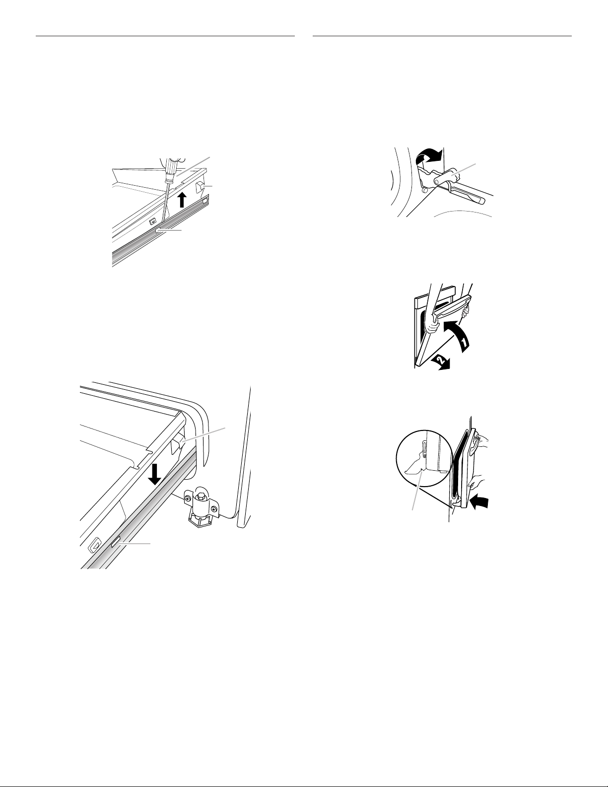
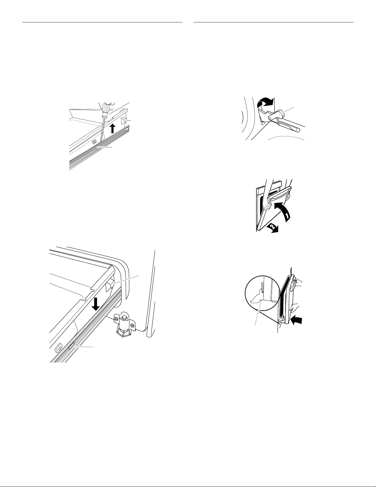
Remove/Replace Drawer
A
B
Remove all items from inside the baking drawer, and then allow
the range to cool completely before attempting to remove the
drawer.
To Remove:
1. Open the drawer to its fully open position.
2. Using a flat-blade screwdriver, gently loosen the drawer
from the glide alignment notch, and then lift up the drawer
alignment tab from the glide.
Oven Door
For normal range use, it is not suggested to remove the oven
door. However, if removal is necessary, make sure the oven is
off and cool. Then, follow these instructions. The oven door
is heavy.
To Remove:
1. Open oven door all the way.
2. Pinch the hinge latch between two fingers and pull forward.
Repeat on other side of oven door.
A
C
A. Flat-blade screwdriver
B. Drawer alignment tab
C. Drawer glide notch
3. Repeat Step 2 on the other side. The drawer is no longer
attached to the drawer glides. Using both hands, pick up the
drawer to complete the removal.
To Replace:
1. Align the forward drawer notches with the notches in the
drawer glides on both sides. Place the rear alignment tabs
into the drawer glides on both sides.
A
A. Hinge latch
3. Close the oven door as far as it will shut.
4. Lift the oven door while holding both sides.
Continue to push the oven door closed and pull it away from
the oven door frame.
To Replace:
1. Insert both hanger arms into the door. Be sure that the hinge
notches are engaged in the oven door frame.
B
A. Drawer alignment tab
B. Drawer glide notch
2. Push the drawer in all the way.
3. Gently open and close the drawer to ensure it is seated
properly on the glides on both sides.
16
A
A. Hinge notch
2. Open the oven door.
The door should be able to open all the way.
3. Move the hinge levers back to the locked position. Check
that the door is free to open and close and is level while
closed. If it is not, repeat the removal and installation
procedures.
Page 17

Complete Installation
1. Check that all parts are now installed. If there is an extra
part, go back through the steps to see which step was
skipped.
2. Check that you have all of your tools.
3. Check that you have all of the range accessories, especially
oven racks. These accessories may be in the range
packaging.
4. Dispose of/recycle all packaging materials.
5. Check that the range is level. See the “Level Range” section.
6. Use a mild solution of liquid household cleaner and warm
water to remove waxy residue caused by shipping material.
Dry thoroughly with a soft cloth. For more information, see
the “Range Care” section of the User Guide.
7. Read the User Guide.
8. Plug power cord into a grounded outlet. Turn power on.
9. Turn on surface burners and oven. See the User Guide for
specific instructions on range operation.
NOTE: Odors and smoke are normal when the oven is used
the first few times.
If Range Does Not Operate, Check the Following:
■ Household fuse is intact and tight, or circuit breaker has not
tripped.
■ Range is plugged into a grounded outlet.
■ Electrical supply is connected.
IMPORTANT: If the range control displays an “F9” or
“F9, E0” error code, the electrical outlet in the home may
be miswired. Disconnect power and contact a qualified
electrician to verify the electrical supply.
10. When the range has been on for 5 minutes, check for heat.
If the range is cold, turn off the range and contact a qualified
electrician.
If You Need Assistance or Service:
Please reference the “Warranty” section of the User Guide to
contact service.
17
Page 18
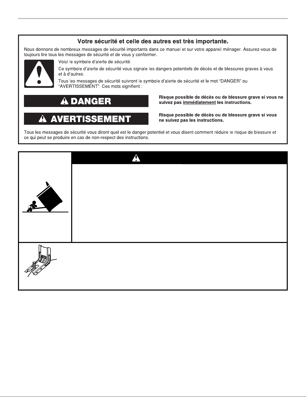
SÉCURITÉ DE LA CUISINIÈRE
AVERTISSEMENT
Risque de basculement
Un enfant ou une personne adulte peut faire basculer la cuisinière, ce qui peut causer un
décès.
Fixer la bride antibasculement au plancher ou au mur, conformément aux instructions
d'installation.
Faire glisser de nouveau la cuisinière de façon à ce que le pied arrière de la cuisinière se
trouve dans la fente de la bride antibasculement.
Réengager la bride antibasculement si la cuisinière a été déplacée.
Ne pas faire fonctionner la cuisinière si la bride antibasculement n'est pas installée et engagée.
Le non-respect de ces instructions peut causer un décès ou des brûlures graves aux enfants et
aux adultes.
Pied de
la cuisinière
18
Bride
antibasculement
Pour vérifier que la bride antibasculement est bien installée et engagée :
• Faire glisser la cuisinière vers l'avant.
• Vérifier que la bride antibasculement est bien fixée au plancher ou au mur.
• Faire de nouveau glisser la cuisinière vers l'arrière de sorte que le pied de la cuisinière
se trouve sous la bride antibasculement.
• Voir les instructions d'installation pour plus de détails.
Page 19

EXIGENCES D’INSTALLATION
Outillage et pièces
Rassembler les outils et pièces nécessaires avant d’entreprendre
l’installation. Lire et observer les instructions fournies avec
chacun des outils de la liste ci-dessous.
Outils nécessaires
■ Mètre-ruban
■ Tournevis à lame plate
■ Tournevis Phillips
■ Niveau
■ Perceuse manuelle ou
électrique
■ Clé ou pince
■ Marqueur ou crayon
■ Ruban adhésif de
■ Tourne-écrou de
(6,4 mm)
■ Tourne-écrou de
(9,5 mm) et
■ Foret de
1
planchers en bois)
■ Cisaille de ferblantier
ou coupe-fils de gros
diamètre (pour couper la
tresse de mise à la terre le
cas échéant)
masquage
■ Clé à cliquet de
1
/4"
(6,4 mm)
Pièces fournies
Vérifier que toutes les pièces sont présentes.
■ Écrous hexagonaux de 10-32 (fixés au bornier) (3)
■ Cosses pour câblage direct (3)
■ Vis n° 10 x 1
antibasculement) (2)
■ Bride antibasculement (à l’intérieur de la cavité du four)
La bride antibasculement doit être solidement fixée à la
cloison arrière ou au plancher. La profondeur du plancher
peut nécessiter des vis plus longues pour l’ancrage de
la bride dans le sous-plancher. Des vis plus longues sont
disponibles auprès de votre quincaillerie locale.
■ Grilles du four (2)
5
/8" (4,1 cm) (pour le montage de la bride
1
/4"
3
/8"
5
/16" (8 mm)
/8" (3 mm) (pour
Pièces nécessaires
En cas d’utilisation d’un ensemble de cordon d’alimentation
électrique :
■ Cordon d’alimentation (homologation UL) conçu pour
l’utilisation avec une cuisinière. Pour service 250 volts
minimum, 40 A ou 50 A, compatible avec une ouverture
de diamètre nominal 13/8" (3,5 cm) pour le raccordement,
et avec cosses rondes ou en fourche à pointes relevées à
l’extrémité de chaque conducteur.
■ Un serre-câble (homologation UL).
Consulter les codes locaux. Vérifier l’alimentation électrique
existante. Voir la section “Spécifications électriques”
correspondante.
Il est recommandé de faire réaliser tous les raccordements
électriques par un électricien qualifié agréé.
Pièces facultatives
Pour acheter ces accessoires ou d’autres, se reporter à la
section “Accessoires” du guide d’utilisation pour les informations
de contact.
■ Trousses de garnitures latérales :
5
/8" (1,7 cm) Blanc - Commander la pièce numéro
W10675027
5
/8" (1,7 cm) Noir - Commander la pièce numéro W10675026
5
/8" (1,7 cm) Acier inoxydable - Commander la pièce numéro
W10675028
11/8" (2,9 cm) Blanc - Commander la pièce numéro
W10731885
11/8" (2,9 cm) Noir - Commander la pièce numéro
W10731886
11/8" (2,9 cm) Acier inoxydable - Commander la pièce
numéro W10731887
■ Panneaux anti-éclaboussures :
Hauteur 6" (15,2 cm), blanc : commander la pièce numéro
W10655448
Hauteur 6" (15,2 cm), noir : commander la pièce numéro
W10655449
Hauteur 6" (15,2 cm), acier inoxydable : commander la pièce
numéro W10655450
19
Page 20
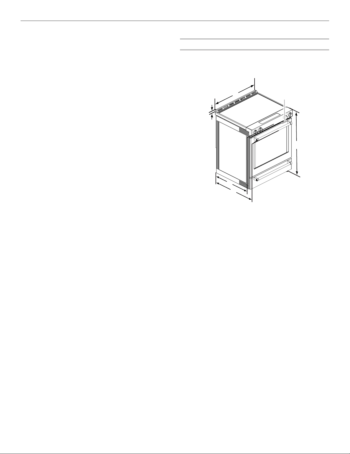
Exigences d’emplacement
A
IMPORTANT : Observer les dispositions de tous les codes et
règlements en vigueur. Ne pas obstruer le flux de combustion
et de ventilation.
■ C’est à l’installateur qu’incombe la responsabilité de
respecter les distances de séparation spécifiées sur la
plaque signalétique. La plaque signalétique se trouve
derrière la porte du four, dans le coin supérieur droit du
châssis.
■ La cuisinière doit être installée à un endroit pratique dans
la cuisine.
■ Dans le cas d’une cuisinière encastrée, l’enceinte doit
recouvrir complètement les côtés et l’arrière de la cuisinière.
■ Toutes les ouvertures dans le mur ou le plancher de
l’emplacement d’installation de la cuisinière doivent être
scellées.
■ Respecter les dimensions indiquées pour les ouvertures à
découper dans les meubles. Ces dimensions constituent
les valeurs minimales des dégagements.
■ La bride antibasculement doit être installée. Pour
l’installation de la bride antibasculement fournie avec
la cuisinière, voir la section “Installation de la bride
antibasculement”.
■ Une source d’électricité avec liaison à la terre est nécessaire.
Voir la section “Spécifications électriques” correspondante.
■ Contacter un installateur de revêtement de sol qualifié, qui
pourra déterminer si le revêtement de sol peut résister à une
température d’au moins 200°F (93°C).
■ Dans le cas de l’installation de la cuisinière sur une
moquette, placer sous la cuisinière un tapis isolant ou une
plaque de contreplaqué de 1/4" (0,64 cm).
IMPORTANT : Afin d’éviter d’endommager les placards,
consulter l’installateur ou le fabricant des placards pour
déterminer si les matériaux utilisés peuvent subir une
décoloration, une déstratification ou d’autres dommages. Ce
four a été conçu conformément aux exigences des normes UL
et CSA International et respecte les températures maximales
permises de 194°F (90°C) pour les placards en bois.
Résidence mobile – Spécifications additionnelles à
respecter lors de l’installation
L’installation de cette cuisinière doit être conforme aux
dispositions de la norme Manufactured Home Construction
and Safety Standard, Title 24 CFR, Part 3280 (anciennement
Federal Standard for Mobile Home Construction and Safety, Title
24, HUD Part 280). Lorsque cette norme n’est pas applicable,
l’installation doit satisfaire aux critères de la norme Standard for
Manufactured Home Installations, ANSI A225.1/NFPA 501A ou
aux dispositions des codes locaux.
Au Canada, l’installation de cette cuisinière doit satisfaire aux
stipulations de la version la plus récente de la norme CAN/
CSAA240 ou des codes locaux en vigueur.
Autres critères à respecter pour une installation en
résidence mobile :
■ Dans le cas de l’installation de cette cuisinière dans une
résidence mobile, la cuisinière doit être fixée au plancher
durant tout déplacement du véhicule. Toute méthode de
fixation de la cuisinière est adéquate dans la mesure où elle
satisfait aux critères des normes mentionnées ci-dessus.
■ Pour une installation en résidence mobile, un câble ou
cordon d’alimentation à quatre conducteurs doit être utilisé.
Le câblage de l’appareil devra être révisé. Voir la section
“Raccordement électrique”.
Dimensions du produit
Ce manuel concerne plusieurs modèles. Votre modèle peut
différer de ceux illustrés. Les dimensions indiquées sont les
dimensions maximales sur tous les modèles.
Modèle KSEB900
B
E
F
A. 13/16" (3,0 cm) de la table de
cuisson au sommet de l’évent
7
B. 29
/8" (75,9 cm)
C. Plaque signalétique (située
derrière la porte du four, dans
le coin supérieur droit du
châssis)
D. 36" (91,4 cm) jusqu’à la
bordure de la table de
cuisson, pieds de nivellement
complètement rétractés*
E. 28
F. 28
IMPORTANT : La cuisinière doit être d’aplomb après
l’installation. Suivre les instructions de la section “Réglage de
l’aplomb de la cuisinière”. Il n’est pas recommandé d’utiliser la
table de cuisson comme référence pour établir l’aplomb de la
cuisinière.
* La cuisinière peut être surélevée d’environ 1" (2,5 cm) en
ajustant les pieds de nivellement.
C
D
5
/16" (71,9 cm) de
profondeur maximale de
l’avant de la console à
l’arrière de la cuisinière
7
/8" (73,3 cm) de
profondeur maximale
entre la poignée et
l’arrière de la cuisinière
20
Page 21
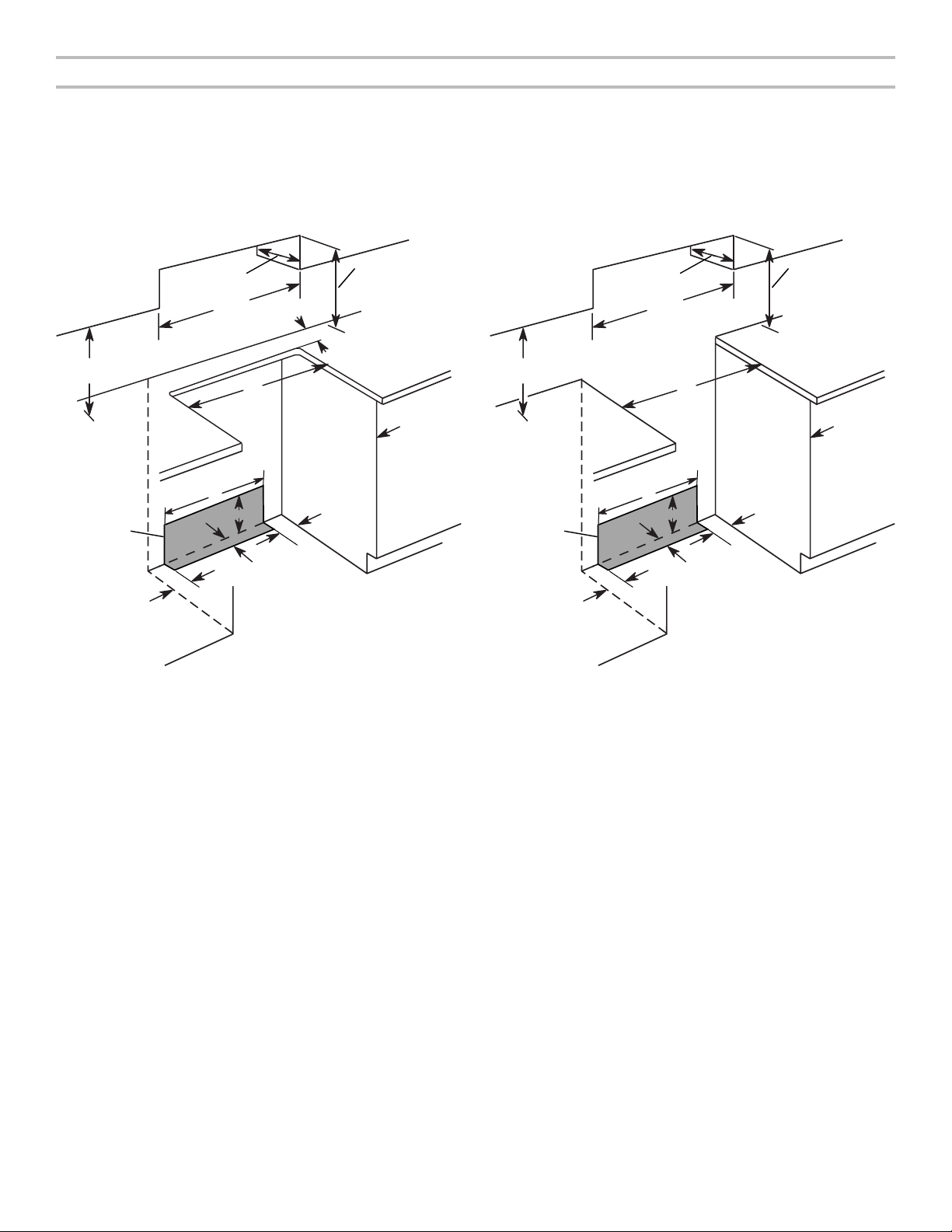
Dimensions du placard
Les dimensions de l’ouverture entre les placards correspondent à une installation entre des placards de 25" (64,0 cm) de profondeur,
avec plan de travail de 24" (61,0 cm) de profondeur et de 36" (91,4 cm) de hauteur.
IMPORTANT : En cas d’installation d’une hotte ou d’un ensemble hotte/four à micro-ondes au-dessus de la cuisinière, suivre les
instructions fournies avec ces appareils concernant les dégagements à respecter au-dessus de la surface de la table de cuisson.
Une cuisinière peut être installée à côté de parois combustibles sans aucun espace.
REMARQUE : Lorsqu’une cuisinière encastrée est glissée dans une ouverture prévue à cet effet, l’avant de la porte du four peut
dépasser du meuble.
Découpe pour cuisinière encastrée Découpe pour cuisinière autoportante
B
D
C
L
A
E
K
G
H
I
F
J
I
A. 18" (45,7 cm) entre le placard latéral supérieur et le plan de travail
B. 13" (33 cm) de profondeur maximale du placard supérieur
C. 30" (76,2 cm) de largeur min. d’ouverture
D. Pour le dégagement minimum par rapport au dessus de la table
de cuisson, voir la REMARQUE*.
E. Largeur min. d’ouverture 30" (76,2 cm)
F. Il est recommandé d’effectuer l’installation de la canalisation de
gaz rigide et de la prise reliée à la terre dans cette zone grisée.
1
G. 13
/8" (33,3 cm)
11
H. 7
/16" (19,5 cm)
13
I. 4
/16" (12,2 cm)
11
J. 3
/16" (9,4 cm) plus la mesure de L
K. La porte du placard ou ses charnières ne doit pas dépasser à
l’intérieur de l’ouverture.
L. La profondeur restante du plan de travail ne doit pas dépasser
1
2
/4" (5,7 cm).
B
D
C
A
E
K
G
H
I
F
J
I
A. 18" (45,7 cm) entre le placard latéral supérieur et le plan de travail
B. 13" (33 cm) de profondeur maximale du placard supérieur
C. 30" (76,2 cm) de largeur min. d’ouverture
D. Pour le dégagement minimum par rapport au dessus de la table de
cuisson, voir la REMARQUE*.
E. Largeur min. d’ouverture 30” (76,2 cm)
F. Il est recommandé d’effectuer l’installation de la canalisation de
gaz rigide et de la prise reliée à la terre dans cette zone grisée.
1
G. 13
/8" (33,3 cm)
11
H. 7
/16" (19,5 cm)
13
I. 4
/16" (12,2 cm)
11
J. 3
/16" (9,4 cm)
K. La porte du placard ou ses charnières ne doit pas dépasser à
l’intérieur de l’ouverture.
* REMARQUE : Distance de séparation de 24" (61,0 cm) ou plus lorsque le fond d’un placard de bois ou de métal est protégé par
une planche ignifugée d’au moins 1/4" (0,64 cm) recouverte d’une feuille métallique d’épaisseur égale ou supérieure à : acier calibre
28 MSG, acier inoxydable 0,015" (0,4 mm), aluminium 0,024" (0,6 mm) ou cuivre 0,020" (0,5 mm).
Distance de séparation minimale de 30" (76,2 cm) entre le dessus de la table de cuisson et le fond d’un placard de bois ou de métal
non protégé.
21
Page 22
Spécications électriques – Canada seulement
AVERTISSEMENT
Risque de choc électrique
Relier la cuisinière à la terre.
Le non-respect de cette instruction peut causer
un décès, un incendie ou un choc électrique.
Si l’on utilise un conducteur distinct de liaison à la terre lorsque
les codes le permettent, il est recommandé qu’un électricien
qualifié vérifie que la liaison à la terre est adéquate et la section
des fils conforme aux codes locaux.
Vérifier que le raccordement à la source d’électricité et le
calibre des conducteurs sont conformes aux prescriptions de
la plus récente édition de la norme CSA C22.1, partie 1 – Code
canadien de l’électricité, et de tout code ou règlement local en
vigueur.
Pour obtenir un exemplaire des normes des codes ci-dessus,
contacter :
Canadian Standards Association
178 Rexdale Blvd.
Toronto, ON M9W 1R3 CANADA
■ En cas de doute quant à la qualité de la liaison à la terre de
lacuisinière, consulter un électricien qualifié.
Intensité nominale
Puissance nominale de la
cuisinière*
120/240 volts 120/208 volts Ampères
8,8 à 16,5 kW 7,8 à 12,5 kW 40 ou 50**
16,6 à 22,5 kW 12,6 à 18,5 kW 50
* La charge NEC calculée est inférieure à la charge totale
con-ectée indiquée sur la plaque signalétique.
** En cas de raccordement à un circuit de 50 A, utiliser un cordon
de 50 A nominaux avec son nécessaire. Pour les ensembles
avec cordon de 50 A nominaux, utiliser des ensembles conçus
pour être utilisés avec une ouverture de raccord d’un diamètre
nominal de 13/8" (3,5 cm).
■ L’emploi d’un disjoncteur est recommandé.
■ Cette cuisinière est équipée d’un cordon électrique
homologué par la CSA International à brancher dans une
prise murale standard 14-50R. Veiller à ce que la prise
murale se trouve à proximité de l’emplacement définitif de
la cuisinière.
spécifiée de l’ensemble
du cordon d’alimentation
et de la protection du
circuit
■ Ne pas utiliser de rallonge.
■ La fiche technique et le schéma de câblage sont situés à
l’arrière de la cuisinière, dans un sachet plastique.
22
Page 23
INSTRUCTIONS D’INSTALLATION
Déballage de la cuisinière
AVERTISSEMENT
Risque du poids excessif
Utiliser deux ou plus de personnes pour déplacer et
installer la cuisinière.
Le non-respect de cette instruction peut causer
une blessure au dos ou d'autre blessure.
1. Ôter les matériaux d’emballage, le ruban adhésif et la
pellicule protectrice de la cuisinière. Garder la base de carton
sous la cuisinière. Ne rien jeter avant d’avoir complètement
terminé l’installation.
2. Retirer les grilles de four et le sachet de pièces du four et
des matériaux d’emballage.
3. Pour retirer le fond en carton, prendre d’abord les 4 coins
en carton de la caisse. Empiler l’un des coins sur un autre.
Répéter avec les 2 autres coins. Les disposer sur le plancher
dans le sens de la longueur derrière la cuisinière, à titre de
support de la cuisinière lorsque celle-ci est placée sur sa
partie postérieure.
4. À 2 personnes au moins, saisir fermement la cuisinière et la
déposer délicatement sur sa partie postérieure, sur les coins
en carton.
5. Retirer le fond en carton.
Les pieds de nivellement peuvent être réglés pendant que
la cuisinière repose sur sa partie postérieure. Voir la section
“Réglage des pieds de nivellement”.
REMARQUE : Pour relever la cuisinière en position verticale,
placer un carton ou un panneau de fibres dur au sol devant la
cuisinière pour protéger le plancher. À 2 personnes au moins,
redresser la cuisinière et la placer sur le carton ou le panneau
de fibres dur.
Installation de la bride antibasculement
AVERTISSEMENT
Risque de basculement
Un enfant ou une personne adulte peut faire basculer la
cuisinière, ce qui peut causer un décès.
Fixer la bride antibasculement au plancher ou au mur,
conformément aux instructions d'installation.
Faire glisser de nouveau la cuisinière de façon à ce que
le pied arrière de la cuisinière se trouve dans la fente
de la bride antibasculement.
Réengager la bride antibasculement si la cuisinière a
été déplacée.
Ne pas faire fonctionner la cuisinière si la bride
antibasculement n'est pas installée et engagée.
Le non-respect de ces instructions peut causer un
décès ou des brûlures graves aux enfants et aux
adultes.
1. Sortir la bride antibasculement de l’intérieur du four.
2. Déterminer la méthode de montage à utiliser : au plancher ou
au mur.
Pour un plancher en pierre ou en briquetage, on peut utiliser
la méthode de montage au mur. En cas d’installation de la
cuisinière dans une résidence mobile, il est impératif de fixer
la cuisinière au sol.
Cette bride antibasculement et les vis peuvent servir avec
des goujons en métal ou en bois.
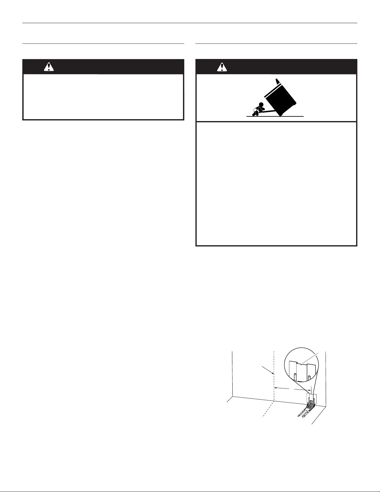
3. Déterminer et marquer l’axe central de l’espace à découper.
Le montage peut être effectué du côté gauche ou droit de la
découpe. Positionner la bride de montage contre le mur
dans l’ouverture, de telle sorte que l’encoche en V de la
bride se trouve à 121/2" (31,8 cm) de l’axe central, tel
qu’illustré.
B
Axe central
A
A. 121/2" (31,8 cm)
B. Encoche en V de la bride
23
Page 24
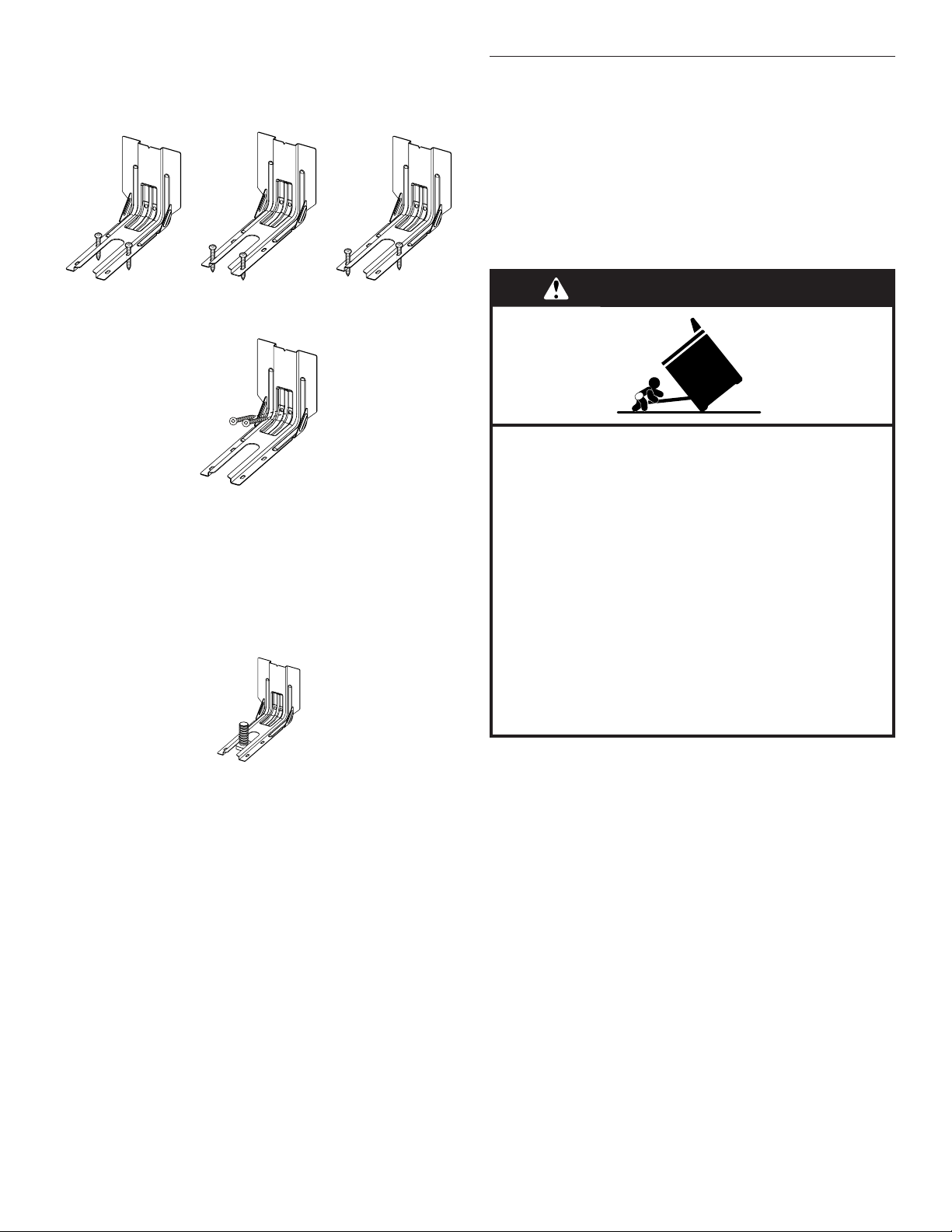
4. Percer deux trous de 1/8" (3 mm) qui correspondent aux trous
de la bride selon la méthode de montage déterminée. Voir
les illustrations suivantes.
Montage au plancher
Réglage des pieds de nivellement
1. Si un ajustement de la hauteur de la cuisinière est
nécessaire, utiliser une clé ou une pince pour desserrer les
4 pieds de nivellement.
Cette opération peut être effectuée alors que la cuisinière
repose sur sa partie postérieure ou sur 2 pieds après avoir
été relevée en position verticale.
REMARQUE : Pour placer à nouveau la cuisinière en
position verticale, placer un carton ou un panneau de fibres
dur devant la cuisinière. À 2 personnes au moins, redresser
la cuisinière et la placer sur le carton ou le panneau de
fibres dur.
Position arrière Position avant Diagonale (2 options)
Montage mural
5. À l’aide des deux vis à tête Phillips n° 10 x 15/8" (4,1 cm)
fournies, visser la bride antibasculement au mur ou au
plancher.
6. Rapprocher la cuisinière le plus près possible de l’ouverture
afin de faciliter les raccordements électriques définitifs.
Retirer la plaque de transport, le carton ou le panneau de
fibres dur de sous la cuisinière.
7. Placer la cuisinière dans son emplacement définitif en
s’assurant que le pied de nivellement arrière glisse dans la
bride antibasculement.
AVERTISSEMENT
Risque de basculement
Un enfant ou une personne adulte peut faire basculer la
cuisinière, ce qui peut causer un décès.
Fixer la bride antibasculement au plancher ou au mur,
conformément aux instructions d'installation.
Faire glisser de nouveau la cuisinière de façon à ce que
le pied arrière de la cuisinière se trouve dans la fente
de la bride antibasculement.
Réengager la bride antibasculement si la cuisinière a
été déplacée.
Ne pas faire fonctionner la cuisinière si la bride
antibasculement n'est pas installée et engagée.
Le non-respect de ces instructions peut causer un
décès ou des brûlures graves aux enfants et aux
adultes.
8. Déplacer la cuisinière vers l’avant sur sa plaque de transport,
son carton ou son panneau de fibres dur pour poursuivre
l’installation de la cuisinière à l’aide des instructions
d’installation suivantes.
24
2. Mesurer la distance entre le haut du plan de travail et le
plancher.
3. Mesurer la distance entre le haut de la table de cuisson et
le bas des pieds de nivellement. Cette distance doit être la
même. Dans le cas contraire, régler les pieds de nivellement
à la hauteur correcte. Les pieds de nivellement peuvent être
desserrés pour ajouter une hauteur maximale de 1" (2,5 cm).
Une longueur minimale de 3/16" (5 mm) est nécessaire pour
engager la bride antibasculement.
REMARQUE : Si un ajustement de la hauteur est effectué
alors que la cuisinière est debout, incliner la cuisinière vers
l’arrière pour ajuster les pieds avant, puis incliner la cuisinière
vers l’avant pour ajuster les pieds arrière.
4. Lorsque la cuisinière est à la hauteur souhaitée, vérifier
que l’espace sous la cuisinière est suffisant pour loger la
bride antibasculement. Avant de faire glisser la cuisinière à
son emplacement final, vérifier qu’il sera possible de faire
glisser la bride antibasculement sous la cuisinière et sur le
pied de nivellement arrière avant l’installation de la bride
antibasculement.
REMARQUE : En cas d’utilisation d’un jeu de garnitures, le
dessus de la table de cuisson doit être plus haut que le plan
de travail. Voir les instructions d’installation fournies avec le
jeu de garnitures pour la hauteur correcte.
Page 25

Réglage de l’aplomb de la cuisinière
1. En fonction de la taille du niveau, le placer sur le bas du four
tel qu’indiqué dans l’une des deux figures ci-dessous.
Contrôler l’aplomb transversal et dans le sens avant/arrière.
2. Si la cuisinière n’est pas horizontale, utiliser une clé ou une
pince pour régler les pieds de nivellement vers le haut ou
vers le bas jusqu’à ce que la cuisinière soit d’aplomb.
REMARQUE : La cuisinière doit être d’aplomb pour obtenir
les résultats de cuisson au four satisfaisants et un nettoyage
optimal avec la technologie d’autonettoyage AquaLift®.
Vérier que la bride antibasculement est
bien installée et engagée
Sur les cuisinières équipées d’un tiroir de remisage de
qualité supérieure :
1. Faire glisser la cuisinière dans son emplacement définitif en
s’assurant que le pied de nivellement arrière glisse dans la
bride antibasculement.
2. Retirer le tiroir de remisage de qualité supérieure. Voir la
section “Dépose et repose du tiroir”.
3. Au moyen d’une torche électrique, inspecter le dessous de la
cuisinière.
4. Vérifier visuellement que le pied arrière de la cuisinière se
trouve dans la fente de la bride antibasculement.
Sur les cuisinières équipées d’un tiroir-réchaud ou
d’un tiroir de cuisson :
1. Rapprocher la cuisinière de son emplacement définitif en
s’assurant que le pied de nivellement arrière glisse dans la
bride antibasculement. Laisser un espace de 1" (2,5 cm)
entre l’arrière de la cuisinière et le mur.
2. Placer l’extérieur du pied contre le bord inférieur avant du
tiroir-réchaud ou tiroir de cuisson pour immobiliser la
cuisinière, puis saisir l’arrière de la cuisinière comme illustré.
3. Tenter d’incliner la cuisinière vers l’avant avec précaution.
En cas de résistance immédiate, cela signifie que le pied
de la cuisinière est engagé dans la bride antibasculement.
Passer à l’étape 8.
4. Si l’arrière de la cuisinière se soulève de plus de 1/2" (1,3 cm)
du plancher sans opposer de résistance, cesser d’incliner
la cuisinière et la reposer doucement sur le plancher.
Le pied de la cuisinière n’est pas engagé dans la bride
antibasculement.
IMPORTANT : Si l’on entend un claquement ou un bruit
d’éclatement lorsqu’on soulève la cuisinière, cela signifie
peut-être que la cuisinière n’est pas bien engagée dans la
bride. Vérifier qu’aucun obstacle n’empêche la cuisinière
de glisser jusqu’au mur ou le pied de la cuisinière de glisser
dans la bride. Vérifier que la bride est fermement maintenue
en place par les vis de montage.
5. Glisser la cuisinière vers l’avant et vérifier que la bride
antibasculement est bien fixée au plancher ou au mur.
6. Faire glisser de nouveau la cuisinière de façon à ce
que son pied arrière se trouve dans la fente de la bride
antibasculement.
7. Répéter les étapes 1 et 2 pour s’assurer que le pied de la
cuisinière est bien engagé dans la bride antibasculement.
Si l’arrière de la cuisinière se soulève de plus de 1/2" (1,3 cm)
du plancher sans opposer de résistance, cela peut signifier
que la bride antibasculement n’est pas correctement
installée. Ne pas faire fonctionner la cuisinière si la bride
antibasculement n’est pas installée et engagée. Se reporter à
la section “Garantie” du guide d’utilisation pour contacter le
service de maintenance.
8. Déplacer la cuisinière à son emplacement définitif. Vérifier
que la cuisinière est d’aplomb en plaçant un niveau dans
le bas du four. Voir la section “Réglage de l’aplomb de la
cuisinière”.
IMPORTANT : Si la cuisinière est déplacée pour le
réglage des pieds de nivellement, vérifier que la bride
antibasculement est bien engagée en répétant les
étapes 1 à 8.
25
Page 26
Dépose et réinstallation du tiroir
A
Enlever tous les articles de l’intérieur du tiroir de cuisson au four
et laisser la cuisinière refroidir complètement avant d’essayer
d’enlever le tiroir.
Dépose :
1. Ouvrir complètement le tiroir.
2. À l’aide d’un tournevis à lame plate, desserrer doucement le
tiroir pour le dégager de l’encoche d’alignement de glissière
et soulever l’onglet d’alignement du tiroir pour le dégager de
la glissière.
B
Porte du four
Il n’est pas recommandé d’enlever la porte du four pour une
utilisation normale. Toutefois, si la dépose est nécessaire,
s’assurer que le four est éteint et froid. Ensuite, suivre les
instructions ci-dessous. La porte du four est lourde.
Démontage :
1. Ouvrir la porte du four complètement.
2. Pincer le loquet de charnière entre les deux doigts et le tirer
vers l’avant. Répéter cette opération pour l’autre côté de la
porte du four.
A
C
A. Tournevis à lame plate
B. Onglet d’alignement du tiroir
C. Encoche de glissière du tiroir
3. Répéter l’étape 2 pour l’autre côté. Le tiroir n’est plus fixé
aux glissières de tiroir. Avec les deux mains, saisir le tiroir
pour le retirer complètement.
Réinstallation :
1. Aligner les encoches de l’avant du tiroir avec les encoches
des glissières latérales à l’intérieur du tiroir (de chaque côté).
Placer les onglets d’alignement arrière dans les glissières de
tiroir (de chaque côté).
A
A. Loquet de charnière
3. Fermer la porte du four aussi loin que possible.
4. Soulever la porte du four en la retenant de chaque côté. Tout
en la maintenant en position fermée, la dégager du cadre de
la porte du four.
Remontage :
1. Insérer les deux bras de suspension dans la porte. Vérifier
que les encoches de charnière sont engagées dans le cadre
de la porte du four.
B
A. Onglet d’alignement du tiroir
B. Encoche de glissière du tiroir
2. Pousser le tiroir complètement.
3. Ouvrir et fermer délicatement le tiroir pour s’assurer qu’il est
bien engagé dans les glissières (de chaque côté).
26
A
A. Encoche de charnière
2. Ouvrir la porte du four.
La porte doit pouvoir s’ouvrir complètement.
3. Remettre les leviers des charnières à la position verrouillée.
Vérifier que la porte s’ouvre et se ferme facilement et qu’elle
est bien droite en position fermée. Si tel n’est pas le cas,
répéter la procédure de dépose et de repose de la porte.
Page 27

Achever l’installation
1. Vérifier que toutes les pièces sont maintenant installées. S’il
reste une pièce, passer en revue les différentes étapes pour
découvrir laquelle aurait été oubliée.
2. Vérifier la présence de tous les outils.
3. Vérifier que tous les accessoires de la cuisinière sont
présents, en particulier les grilles du four. Ces accessoires
peuvent se trouver dans les matériaux d’emballage de la
cuisinière.
4. Éliminer/recycler tous les matériaux d’emballage.
5. Vérifier que la cuisinière est d’aplomb. Voir la section
“Réglage de l’aplomb de la cuisinière”.
6. Utiliser une solution d’eau tiède et de nettoyant ménager
doux pour éliminer tout résidu de cire laissé par les
matériaux d’emballage. Sécher soigneusement avec un
chiffon doux. Pour plus d’informations, consulter la section
“Entretien de la cuisinière” dans le Guide d’utilisation.
7. Lire le guide d’utilisation.
8. Brancher le cordon d’alimentation électrique dans une prise
de courant reliée à la terre. Mettre l’appareil sous tension.
9. Mettre en marche les brûleurs de surface et le four. Pour
des instructions spécifiques concernant l’utilisation de la
cuisinière, consulter le Guide d’utilisation.
REMARQUE : Au cours des premières utilisations du four, il
est normal qu’il dégage des odeurs et de la fumée.
Si la cuisinière ne fonctionne pas, contrôler ce qui suit :
■ Les fusibles du domicile sont intacts et serrés; le disjoncteur
n’est pas déclenché.
■ La cuisinière est branchée sur une prise reliée à la terre.
■ La prise de courant est correctement alimentée.
IMPORTANT : Si le tableau de commande de la cuisinière
affiche le code d’erreur “F9” ou “F9, E0”, cela peut signifier
que le câblage de la prise électrique est défectueux.
Déconnecter la source de courant électrique et contacter un
électricien qualifié pour qu’il contrôle le circuit d’alimentation
électrique.
10. Après 5 minutes de fonctionnement de la cuisinière, vérifier
la chaleur. Si la cuisinière est froide, l’éteindre et contacter un
électricien qualifié.
Pour obtenir de l’assistance ou une visite de service :
Se reporter à la section “Garantie” du guide d’utilisation pour
contacter le service de maintenance.
27
Page 28

W11047691A
®
/™ ©2017 Whirlpool. Used under license in Canada. All rights reserved.
Utilisé sous licence au Canada. Tous droits réservés.
01/17
 Loading...