

Ikea IBMS1455WS0, IBMS1455WW0 Installation Guide
BUILT-INMICROWAVE OVEN
INSTALLATIONINSTRUCTIONS
24" (61.0 cm) or 30" (76.2 cm)
This product is suitable for use above electric or gas built-in ovens, and below non-vented electric or gas cooktops. This product is not
suitable for use below downdraft cooktops.
These installation instructions cover different models. The appearance of your particular model may differ slightly from the illustrations
in these Installation Instructions.
INSTRUCTIONSD'INSTALLATIONDr) FOUR
MICRO-ONDES ENCASTRE
24" (61,0 cm) ou 30" (76,2 cm)
Ce produit convient a une utilisation au-dessus de fours encastres electriques ou & gaz, et au-dessous de tables de cuisson
electriques ou &gaz sans decharge a I'exterieur. Ce produit ne convient pas a une utilisation au-dessous de tables de cuisson avec
extraction par le bas.
Ces instructions d'installation sont valables pour plusieurs modeles. IIse peut que I'apparence de votre propre modele soit legerement
differente de celle illustree dans ces Instructions d'installation.
Table of Contents / Tabledes mati@res
BUILT-IN MICROWAVE OVEN SAFETY ................................. 1
INSTALLATION REQUIREMENTS ........................................... 2
Tools and Parts ...................................................................... 2
Location Requirements .......................................................... 2
Minimum Dimensions ............................................................. 2
Product Dimensions ............................................................... 4
Electrical Requirements ......................................................... 4
INSTALLATION INSTRUCTIONS ............................................. 5
Install Spacer Strips ............................................................... 5
Install the Microwave Oven
(24" [61.0 cm] Installation Only) ............................................. 5
Install the Microwave Oven
(30" [76.2 cm] Installation Only) ............................................. 6
Complete Installation ............................................................. 8
ASSISTANCE ............................................................................. 8
SECURITE DU FOUR A MICRO-ONDES ENCASTRE ..................... 9
EXIGENCES D'INSTALLATION .......................................................... 9
Outillage et composants .................................................................. 9
Exigences d'emplacement ............................................................. 10
Dimensions minimales ................................................................... 10
Dimensions du produit ................................................................... 12
Specifications elect riques .............................................................. 12
INSTRUCTIONS D'INSTALLATION ................................................. 13
Installation des bandes d'espacement .......................................... 13
Installation du four & micro-ondes
(installation de 24" [61 cm] uniquement) ........................................ 13
Installation du four & micro-ondes
(Installation de 30" [76,2 cm] uniquement) ..................................... 14
Achever I'installation ....................................................................... 16
ASSISTANCE ..................................................................................... 16
BUILT-INMICROWAVE OVEN SAFETY
Your safety and the safety of others are very important.
We have provided many important safety messages in this manual and on your appliance. Always read and obey all safety
messages.
This is the safety alert symbol.
This symbol alerts you to potential hazards that can kill or hurt you and others.
All safety messages will follow the safety alert symbol and either the word "DANGER" or "WARNING."
These words mean:
You can be killed or seriously injured if you don't immediately
follow instructions.
You can be killed or seriously injured if you don't follow
instructions.
All safety messages will tell you what the potential hazard is, tell you how to reduce the chance of injury, and tell you what can
happen if the instructions are not followed.
W10321811A
INSTALLATIONREQUIREMENTS
t'O0_S 3_J
Tools Needed
Gather the required tools and parts before starting installation.
Read and follow the instructions provided with any tools
listed here.
• Measuring tape • Drill
• Pencil • 5/64" (2 mm) drill bit
• T10 TORX®tscrewdriver • 1/4" (6 mm) shim*
*Shim may be needed for 30" (76.2 cm) installation in double-
walled cabinetry (having outer walls that protrude past the front
surface of the cutout opening). See Step 7 in "Install the
Microwave Oven (30" [76.2 cm] Installation Only)" section.
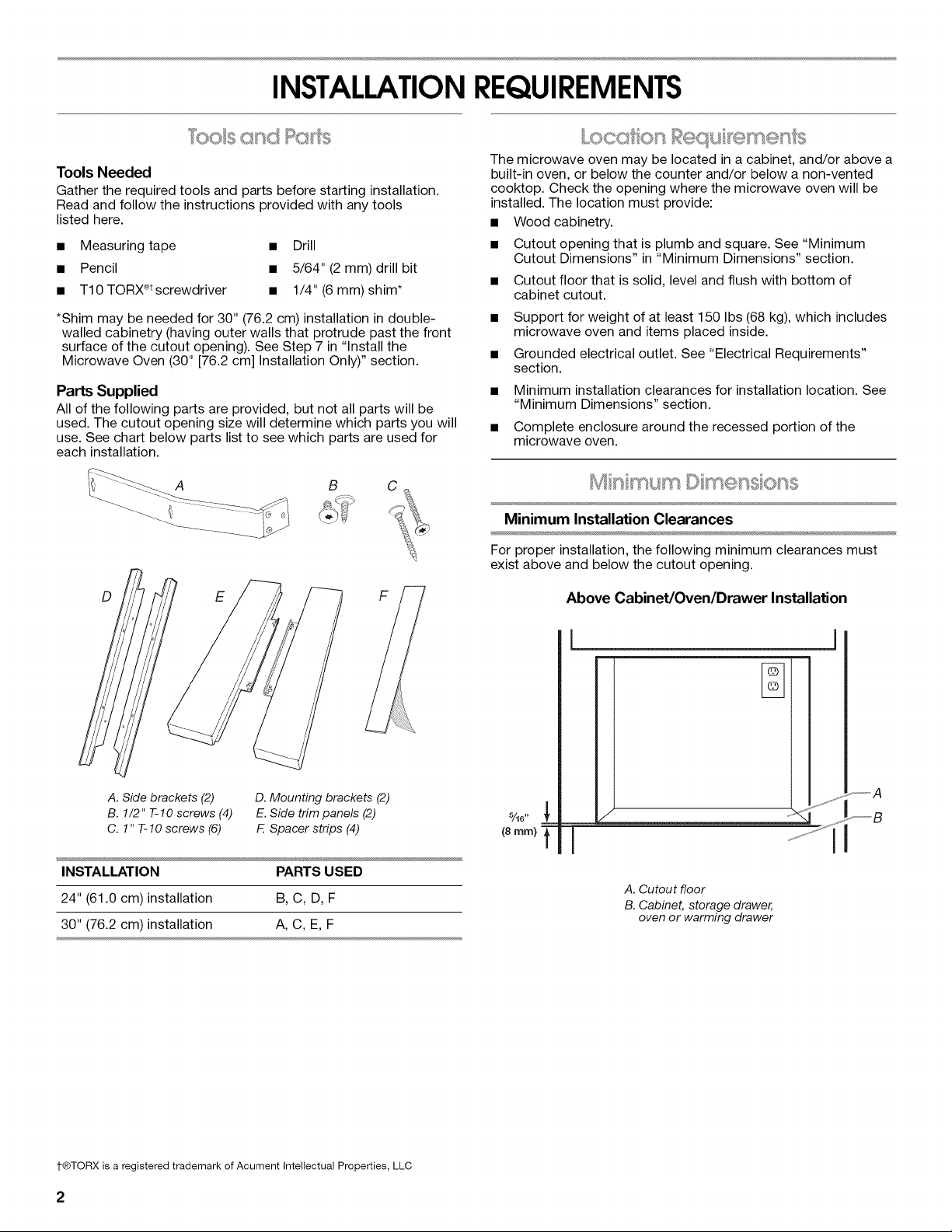
Parts Supplied
All of the following parts are provided, but not all parts will be
used. The cutout opening size will determine which parts you will
use. See chart below parts list to see which parts are used for
each installation.
A
The microwave oven may be located in a cabinet, and/or above a
built-in oven, or below the counter and/or below a non-vented
cooktop. Check the opening where the microwave oven will be
installed. The location must provide:
• Wood cabinetry.
• Cutout opening that is plumb and square. See "Minimum
Cutout Dimensions" in "Minimum Dimensions" section.
• Cutout floor that is solid, level and flush with bottom of
cabinet cutout.
Support for weight of at least 150 Ibs (68 kg), which includes
microwave oven and items placed inside.
Grounded electrical outlet. See "Electrical Requirements"
section.
• Minimum installation clearances for installation location. See
"Minimum Dimensions" section.
• Complete enclosure around the recessed portion of the
microwave oven.
Minimum Installation Clearances
D E
A. Side brackets (2) D. Mounting brackets (2)
B. 1/2" T-10 screws (4) E. Side trim panels (2)
C. 1" T-IO screws (6) F. Spacer strips (4)
INSTALLATION PARTS USED
24" (61.0 cm)installation B, C, D, F
30" (76.2 cm)installation A, C, E, F
For proper installation, the following minimum clearances must
exist above and below the cutout opening.
Above Cabinet/Oven/Drawer Installation
I
A. Cutout floor
B. Cabinet, storage drawer,
oven or warming drawer
I"®TORX is a registered trademark of Acument Intellectual Properties, LLC
2

MinimumInstallationClearances- continued
Below Counter Installation Below Built-in Cooktop Installation
C
(25rnm) f
f_,_jS_,_,H, j_
5/16"
(8 ram) t
A. Cutout floor
B. Cabinet, storage drawer, oven or warming drawer
....f_,'Y
I
C. Countertop
D. Built-in cooktop (non-vented)
3"
(76 mm)
See note
bemow.
5/16"
t (8 mm)
NOTE: The bottom of the cooktop may be sunk into the counter and lower cabinet. The minimum 3" (7.6 cm) clearance must exist
below the lowest point of the cooktop, and there must be no interference between any part of the cooktop (including any gas fittings)
and the microwave oven.
MinimumCutoutDimensions
NOTE: Depth dimension may be 213/4"(55.2 cm) with non-flush
receptacle only if the receptacle is located in upper right or upper
left corner. See "Cutout Top View."
Cutout Top View
A B C D
*With flush receptacle, or with non-flush receptacle located in
upper right or upper left corner of cutout.
**With non-flush receptacle.
DIMENSION 24" (61.0 CM) 30" (76.2 CM)
INSTALLATION INSTALLATION
Width 221/2"(57.2 cm) 2815/32'' (72.3 cm)
_+1/32" (1 mm) _+1/16" (2 mm)
Height Min. 173/4"(45.1 cm) for all installations
Depth 213/4'' (55.2 cm) with flush receptacle, or with
non-flush receptacle located in upper right or
upper left corner;
261/4"(66.7 cm) with non-flush receptacle
"_ "m)
Jt
A. Microwave oven
B. Non-flush receptacle
C. Flush receptacle
D. Non-flush receptacle located in upper right
or upper/eft corner

17_%d '
(45.5crn)* Electrical Shock Hazard
Plug into a grounded 3 prong outlet.
Do not remove ground prong.
Do not use an adapter.
Do not use an extension cord.
(59.5)cm*_ Failure to follow these instructions can result in death,
fire, or electrical shock.
*Measurements include front facing of microwave oven. Depth Observe all governing codes and ordinances.
measurement also includes door handle. Required:
[] A 120 Volt, 60 Hz, AC only, 15- or 20-amp electrical supply
with a fuse or circuit breaker.
Recommended:
[] A time-delay fuse or time-delay circuit breaker.
[] A separate circuit serving only this microwave oven.
GROUNDING iNSTRUCTiONS
[] For all cord connected appliances:
The microwave oven must be grounded. In the event of
an electrical short circuit, grounding reduces the risk of
electric shock by providing an escape wire for the electric
current. The microwave oven is equipped with a cord
having a grounding wire with a grounding plug. The plug
must be plugged into an outlet that is properly installed
and grounded.
WARNING: Improper use of the grounding plug can
result in a risk of electric shock. Consult a qualified
electrician or serviceman if the grounding instructions are
not completely understood, or if doubt exists as to whether
the microwave oven is properly grounded.
Do not use an extension cord. If the power supply cord is
too short, have a qualified electrician or serviceman install
an outlet near the microwave oven.
SAVETHESE iNSTRUCTiONS
4
INSTALLATIONINSTRUCTIONS
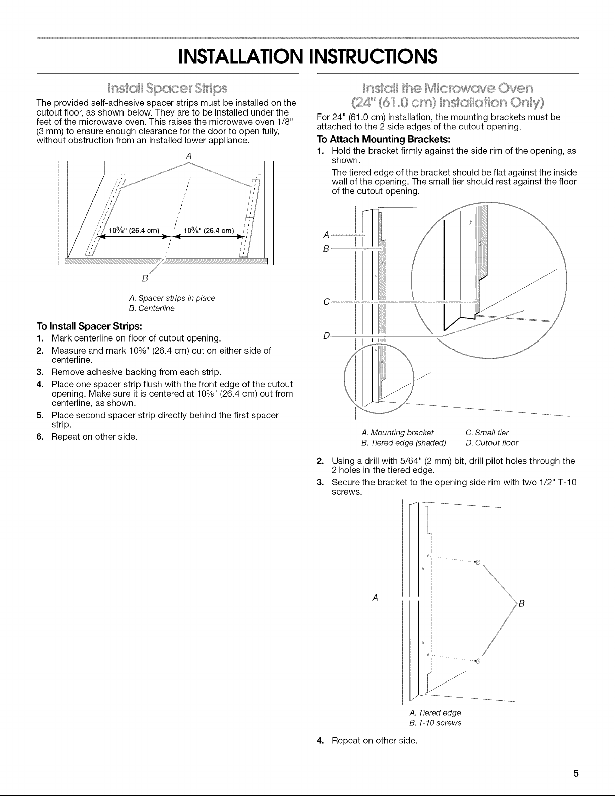
The provided self-adhesive spacer strips must be installed on the
cutout floor, as shown below. They are to be installed under the
feet of the microwave oven. This raises the microwave oven 1/8"
(3 ram) to ensure enough clearance for the door to open fully,
without obstruction from an installed lower appliance.
/
i
/
/
/
i
10s/8" (26.4 crn)
/ 103/8" (26.4 crn)
B
A. Spacer strips in place
B. Centerllne
To Install Spacer Strips:
1. Mark centerline on floor of cutout opening.
2. Measure and mark 103/8'' (26.4 cm) out on either side of
centerline.
3.
Remove adhesive backing from each strip.
4.
Place one spacer strip flush with the front edge of the cutout
opening. Make sure it is centered at 103/8'' (26.4 cm) out from
centerline, as shown.
5,
Place second spacer strip directly behind the first spacer
strip.
6.
Repeat on other side.
f'O,_" (6© ,,,+<rdt O_/yJ+'
%6,+/"_' o,. %J_l l,#iJ
For 24" (61.0 cm) installation, the mounting brackets must be
attached to the 2 side edges of the cutout opening.
To Attach Mounting Brackets:
1. Hold the bracket firmly against the side rim of the opening, as
shown.
The tiered edge of the bracket should be flat against the inside
wall of the opening. The small tier should rest against the floor
of the cutout opening.
C
D
A. Mounting bracket
B. Tiered edge (shaded)
C. Small tier
D. Cutout floor
2. Using a drill with 5/64" (2 mm) bit, drill pilot holes through the
2 holes in the tiered edge.
3. Secure the bracket to the opening side rim with two 1/2" T-10
screws.
.... _2_'
A ...............................................................
A. Tiered edge
B. T-IO screws
4. Repeat on other side.
 Loading...