

Ikea IBD550PRS02, IBD550PRS04, IBD550PRS05, IBD550PWS00, IBD650PXS00 Installation Guide
...Page 1
INSTALLATIONINSTRUCTIONS
30" (76.2 CM) ELECTRICSINGLEAND DOUBLE
BUILT-INOVEN
INSTRUCTIONSD'INSTALLATION
FOURELECTRIQUEENCASTRE30" (76,2 CM) -
SIMPLEETDOUBLE
TableofContents ITabledes mah_res
BUILT-IN OVEN SAFETY .............................................................. 2
INSTALLATION REQUIREMENTS ............................................... 3
Tools and Parts ........................................................................... 3
Location Requirements .............................................................. 3
Electrical Requirements .............................................................. 5
INSTALLATION INSTRUCTIONS ................................................. 6
Prepare Built-In Oven ................................................................. 6
Make Electrical Connection ........................................................ 6
Install Oven ................................................................................. 7
Complete Installation .................................................................. 8
SI_CURITI_ DU FOUR ENCASTRI_ ............................................... 9
EXIGENCES D'INSTALLATION ................................................. 10
Outillage et pieces .................................................................... 10
Exigences d'emplacement ....................................................... 10
Specifications electriques ........................................................ 12
INSTRUCTIONS D'INSTALLATION ........................................... 13
Preparation du four encastre .................................................... 13
Raccordement electrique ......................................................... 13
Installation du four .................................................................... 15
Achever I'installation................................................................. 16
iMPORTANT:
Save for local electrical inspector's use.
iMPORTANT :
,&,conserver pour consultation par I'inspecteur local des installations 61ectriques.
8303102B
Page 2

BUILT-INOVEN SAFETY
Your safety and the safety of others are very important.
We have provided many important safety messages in this manual and on your appliance. Always read and obey all safety
messages.
This is the safety alert symbol.
This symbol alerts you to potential hazards that can kill or hurt you and others.
All safety messages will follow the safety alert symbol and either the word "DANGER" or "WARNING."
These words mean:
You can be killed or seriously injured if you don't immediately
follow instructions.
You can be killed or seriously injured if you don't follow
instructions.
All safety messages will tell you what the potential hazard is, tell you how to reduce the chance of injury, and tell you what can
happen if the instructions are not followed.
2
Page 3
INSTALLATIONREQUIREMENTS
Gather the required tools and parts before starting installation.
Read and follow the instructions provided with any tools listed
here.
Tools needed
• Phillips screwdriver
• Measuring tape
• Drill (for wall cabinet installations)
• 1" (25 ram) drill bit (for wall cabinet installations)
• Level
Parts needed
• UL listed or CSA approved conduit connector
• UL listed wire connectors
Parts supplied
• Two #8-14 x 1" screws
• Bottom vent (supplied on some models)
• Two #8-18 x 3/8"screws - bottom vent (supplied on some
models)
• Side trims (supplied on some models)
• Two #8-18 x 3/8"screws - side trim (supplied on some
models)
Check local codes. Check existing electrical supply. See
"Electrical Requirements."
It is recommended that all electrical connections be made by a
licensed, qualified electrical installer.
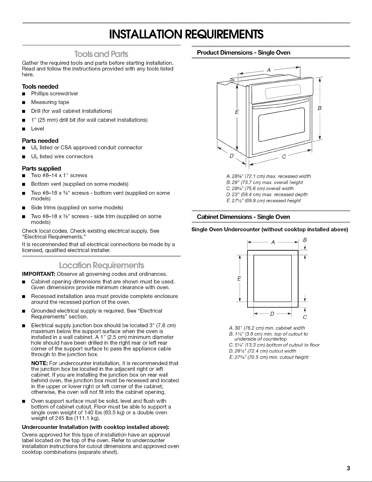
Product Dimensions - Single Oven
A. 28%" (72.1 cm) max. recessed width
B. 29" (73. 7 cm) max. overall height
C. 29s/4'' (75.6 cm) overall width
D. 23" (58.4 cm) max. recessed depth
E. 271/_''(69.9 cm) recessed height
Cabinet Dimensions - Single Oven
Single Oven Undercounter (without cooktop installed above)
A
B
IMPORTANT: Observe all governing codes and ordinances.
• Cabinet opening dimensions that are shown must be used.
Given dimensions provide minimum clearance with oven.
• Recessed installation area must provide complete enclosure
around the recessed portion of the oven.
• Grounded electrical supply is required. See "Electrical
Requirements" section.
Electrical supply junction box should be located 3" (7.6 cm)
maximum below the support surface when the oven is
installed in a wall cabinet. A 1" (2.5 cm) minimum diameter
hole should have been drilled in the right rear or left rear
corner of the support surface to pass the appliance cable
through to the junction box.
NOTE: For undercounter installation, it is recommended that
the junction box be located in the adjacent right or left
cabinet. If you are installing the junction box on rear wall
behind oven, the junction box must be recessed and located
in the upper or lower right or left corner of the cabinet;
otherwise, the oven will not fit into the cabinet opening.
Oven support surface must be solid, level and flush with
bottom of cabinet cutout. Floor must be able to support a
single oven weight of 140 Ibs (63.5 kg) or a double oven
weight of 245 Ibs (111.1 kg).
Undercounter Installation (with cooktop installed above):
Ovens approved for this type of installation have an approval
label located on the top of the oven. Refer to undercounter
installation instructions for cutout dimensions and approved oven
cooktop combinations (separate sheet).
i
" D
A. 30" (76.2 cm) min. cabinet width
B. 11/_'' (3.8 cm) min. top of cutout to
underside of countertop
C. 51/4'' (13.3 cm) bottom of cutout to floor
D. 281/_'' (72.4 cm) cutout width
E. 27s/4'' (70.5 cm) min. cutout height
+
C
Page 4

Single Oven Installed in Cabinet
_A_
F _D_
Cabinet Dimensions - Double Oven
Double Oven Installedin Cabinet
B
B
Y
F
E
A. 30" (76.2 cm) min. cabinet width
B. 1" (2.5 cm) top of cutout to bottom of upper cabinet door
C. 32" (81.3 cm) bottom of cutout to floor
D. 281/2''(72.4 cm) cutout width
E. 11/2'' (3.8 cm) min. bottom of cutout to top of cabinet door
F. 273/4 '' (70.5 cm) min. cutout height
Product Dimensions - Double Oven
t
C
E
A. 30" (76.2 cm) min. cabinet width
B. 1" (2.5 cm) top of cutout to bottom of upper cabinet door
C. 143/4''(37.5 cm) bottom of cutout to floor
D. 281/2" (72.4 cm) cutout width
E. 11/2"(3.8 cm) min. bottom of cutout to top of cabinet door
F. 493/4'' (126.4 cm) min. cutout height
Cabinet Side View - Double or Single Oven
__/
E-.
D
C
/C
A. 28%" (72.1 cm) max. recessed width
B. 51" (129.5 cm) max. overall height
C. 293/4''(75.6 cm) overall width
D. 23" (58.4 cm) max. recessed depth
E. 491/2''(125.7 cm) recessed height
A. 231/4'' (59.1 cm) min. cutout depth
B. 23" (58.4 cm) recessed oven depth
C. Oven front
D. Recessed oven
E.Cabinet
Cabinet filler kits are available from your dealer. Use matching
color kit if oven is smaller than your cabinet opening.
Single oven filler height is 35A6'' (8.4 cm)
Black - 4378941
White - 4378942
Almond - 4378943
Double oven filler height is 6sA6'' (16 cm)
Black - 4378947
White - 4378948
Almond - 4378949
Page 5
Ifcodespermitandaseparategroundwireisused,itis
recommendedthataqualifiedelectricalinstallerdeterminethat
thegroundpathandthewiregaugeareinaccordancewithlocal
codes.
Checkwithaqualifiedelectricalinstallerifyouarenotsurethe
ovenisproperlygrounded.
Thisovenmustbeconnectedtoagroundedmetal,permanent
wiringsystem.
Besurethattheelectricalconnectionandwiresizeareadequate
andinconformancewiththeNationalElectricalCode,ANSI/
NFPA70-latesteditionorCSAStandardsC22.1-94,Canadian
ElectricalCode,Part1andC22.2No.O-M91-1atestedition,and
alllocalcodesandordinances.
Acopyoftheabovecodestandardscanbeobtainedfrom:
NationalFireProtectionAssociation
OneBatterymarchPark
Quincy,MA02269
CSAInternational
8501EastPleasantValleyRoad
Cleveland,OH44131-5575
Electrical Connection
To properly install your oven, you must determine the type of
electrical connection you will be using and follow the instructions
provided for it here.
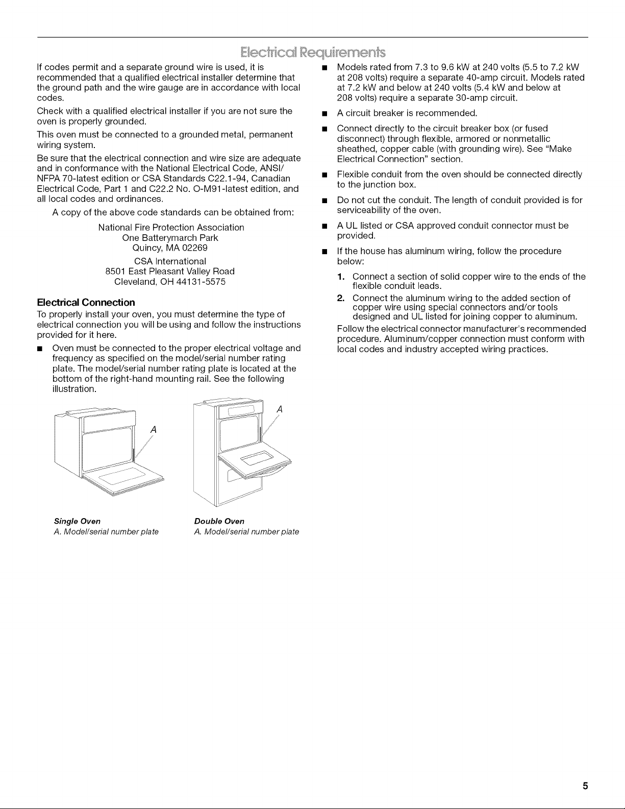
• Oven must be connected to the proper electrical voltage and
frequency as specified on the model/serial number rating
plate. The model/serial number rating plate is located at the
bottom of the right-hand mounting rail. See the following
illustration.
Models rated from 7.3 to 9.6 kW at 240 volts (5.5 to 7.2 kW
at 208 volts) require a separate 40-amp circuit. Models rated
at 7.2 kW and below at 240 volts (5.4 kW and below at
208 volts) require a separate 30-amp circuit.
A circuit breaker is recommended.
Connect directly to the circuit breaker box (or fused
disconnect) through flexible, armored or nonmetallic
sheathed, copper cable (with grounding wire). See "Make
Electrical Connection" section.
• Flexible conduit from the oven should be connected directly
to the junction box.
• Do not cut the conduit. The length of conduit provided is for
serviceability of the oven.
• A UL listed or CSA approved conduit connector must be
provided.
• If the house has aluminum wiring, follow the procedure
below:
1. Connect a section of solid copper wire to the ends of the
flexible conduit leads.
2. Connect the aluminum wiring to the added section of
copper wire using special connectors and/or tools
designed and UL listed for joining copper to aluminum.
Follow the electrical connector manufacturer's recommended
procedure. Aluminum/copper connection must conform with
local codes and industry accepted wiring practices.
Single Oven
A. Model/serial number plate
Double Oven
A. Model/serial number plate
Page 6

INSTALLATIONINSTRUCTIONS
1. Decide on the final location for the oven. Locate existing
wiring to avoid drilling into or severing wiring during
installation.
Excessive Weight Hazard
Use two or more people to move and install oven.
Failure to do so can result in back or other injury.
2.
To avoid floor damage, set the oven onto cardboard prior to
installation. Do not use handle or any portion of the front
frame for lifting.
On models with shipping feet attached:
To avoid product damage, do not remove the shipping feet at
the front lower corners of the oven. The shipping feet will help
keep the lower oven trim from being damaged until the oven
is inserted into cabinet.
3. Remove the shipping materials and tape from the oven.
4. Remove the hardware package from inside the bag
containing literature.
5. Remove and set aside racks and other parts from inside the
oven.
6. Move oven and cardboard close to the oven's final location.
4,
Install a UL listed or CSA approved conduit connector to the
junction box.
A.....................i_
A. UL listed or CSAapproved conduit connector
5. Route the flexible conduit from the oven to the junction box
through a UL listed or CSA approved conduit connector.
6. Tighten screws on conduit connector.
7. See "Electrical Connection Options Chart" to complete
installation for your type of electrical connection.
Electrical Connection Options Chart
If your home has: Go to section:
4-wire 4-wire Cable from Home
Power Supply
I/2"
(1,3 cm)
3-wire 3-wire Cable from Home
Mc, <®Eecru: Connect on
Electrical Shock Hazard
Disconnect power before servicing.
Use 8 gauge solid copper wire.
Electrically ground oven.
Failure to follow these instructions can result in death,
fire, or electrical shock.
This oven is manufactured with a neutral (white) power supply
wire and a cabinet-connected green (or bare) ground wire twisted
together.
1. Disconnect power.
2. Feed the flexible conduit from the oven through the opening
in the cabinet.
3. Remove junction box cover, if it is present.
'L_._ Power Supply
I/2"
)
4-Wire Cable from Home Power Supply
IMPORTANT: Use the 4-wire cable from home power supply in
the U.S. where local codes do not allow grounding through
neutral, New Branch circuit installations (1996 NEC), mobile
homes and recreational vehicles, new construction and in
Canada.
_ ............................................E
A ..... __
D
A. Cable from home power supply
B. Black wires
C. Red wires
D. 4-wire flexible conduit from oven
E. Junction box
",,%,
F. White wires
G. UL listed wire connectors
H. Green (or bare) ground wires
I. UL listed or CSA approved
conduit connector
I
1. Connect the 2 black wires (B) together using a UL listed wire
connector.
2. Connect the 2 red wires (C) together using a UL listed wire
connector.
6
Page 7

3. Untwist white wire from green (or bare) ground wire coming
from the oven.
4. Connect the 2 white wires (F) together using a UL listed wire
connector.
5. Connect the green (or bare) ground wire (H) from the oven
cable to the green (or bare) ground wire (in the junction box)
using a UL listed wire connector.
6. Install junction box cover.
3-Wire Cable from Home Power Supply - U.S. Only
IMPORTANT: Use the 3-wire cable from home power supply
where local codes permit a 3-wire connection.
A
B
G
D
E
2.
Push against seal area of front frame to push oven into
cabinet until shipping feet almost contact cabinet.
A. Shipping foot
3. On models with shipping feet, use a Phillips screwdriver to
remove screws attaching the shipping feet.
4. Push oven completely into cabinet and center oven into
cabinet cutout.
5. Securely fasten oven to cabinet using the #8-14 x 1" screws
(2 for single oven, 4 for double oven) provided. Insert the
screws through holes in mounting rails. Do not overtighten
screws.
ii
A i
.................................................................il
0
A. Cable from home power supply
B. Junction box
C. Black wires
D. White wires
E. Green (or bare) ground wire
(from oven)
F. 4-wire flexible conduit from oven
G. Red wires
H. UL listed wire connectors
I. UL listed or CSA approved
conduit connector
1. Connect the 2 black wires (C) together using a UL listed wire
connector.
2. Connect the 2 white wires (D) and the green (or bare) ground
wire (of the oven cable) using a UL listed wire connector.
3. Connect the 2 red wires (G) together using a UL listed wire
connector.
4. Install junction box cover.
1=
Using 2 or more people, lift oven partially into cabinet cutout
using the oven opening as an area to grip.
NOTE: Push against seal area of oven front frame when
pushing oven into cabinet. Do not push against outside
edges.
\
C _-----L_ C ....................................
B
A. Mounting rail
B. Insert #8-14 x 1" screw.
6.
On some models, the oven vent is taped to the side of the
oven. See the following instructions to install.
• Insert the vent tabs (B) into slots (A) in the oven frame.
• With one #8-18 x 3/8"screw (C) for each side of the vent,
fasten vent securely to the oven.
A B
\
\
D
C
A. Oven frame slot
B. Vent tab
C. #8-18 x 3/8" screw
D. Oven vent
Page 8

7. Slide top end of each trim piece upward onto oven side rails.
r ....................
[ / ...............
<
Jl
8. Push each trim piece into place at bottom of trim.
A. Push trim into place and replace screw.
9. Use screws to attach each trim piece to oven.
10. Replace oven racks.
11. Replace oven door by inserting ends of hinges into hinge
slots in the oven frame.
12. Push hinges in as far as they will go and open the oven door.
You should feel the oven door drop into place.
13. Rotate both hinge latches back to the locked position.
14. Check that the door is free to open and close. If it is not,
repeat the removal and installation procedures.
15. Repeat for lower oven door.
16. Reconnect power.
17. Display panel will light briefly, and "PF" should appear in the
display.
18. If display panel does not light, please reference the
"Assistance or Service" section of the Use and Care Guide or
contact the dealer from whom you purchased your oven.
1. Check that all parts are now installed. If there is an extra part,
go back through the steps to see which step was skipped.
2. Check that you have all of your tools.
3. Dispose of/recycle all packaging materials.
4. For oven use and cleaning, read the Use and Care Guide.
Check Operation of Oven
1. Turn power on. "PF" should appear in the display. Turn the
selector knob to OFF and press ENTER button twice.
2. Turn knob selector to BAKE, "350F" will show on the display.
Press ENTER and look through the oven window. The top and
bottom elements should glow red.
If oven(s) does not operate, check the following:
• Household fuse is intact and tight; or circuit breaker has
not tripped.
• Electrical supply is connected.
• See "Troubleshooting" section in the Use and Care Guide.
3. When oven has been on for 5 minutes, feel for heat.
If you do not feel heat, turn off the oven and contact a
qualified technician.
4. Press CANCEL and turn knob selector to OFE
5. On double oven models, repeat steps 2-4 for the other oven.
To set the clock and other oven functions, refer to the Use and
Care Guide.
If you need Assistance or Service:
Please reference the "Assistance or Service" section of the Use
and Care Guide or contact the dealer from whom you purchased
your built-in oven.
8
Page 9

SECURITEDU FOURENCASTRE
Votre securite et celle des autres est tres importante.
Nous donnons de nombreux messages de s_curit_ importants dans ce manuel et sur votre appareil m_nager. Assurez-vous de
toujours lire tousles messages de s_curit_ et de vous y conformer.
Ce symbole d'alerte de s_curit_ vous signale les dangers potentiels de d_c_s et de blessures graves & vous
et & d'autres.
Voici le symbole d'alerte de s_curit&
Tousles messages de s_curit_ suivront le symbole d'alerte de s_curit_ et le mot "DANGER" ou
"AVERTISSEMENT". Ces mots signifient •
Risque possible de d_cbs ou de blessure grave si vous ne
suivez pas imm_diatement les instructions.
Risque possible de d_cbs ou de blessure grave si vous
ne suivez pas les instructions.
Tousles messages de s_curit_ vous diront quel est le danger potentiel et vous disent comment r_duire le risque de blessure et
ce qui peut se produire en cas de non-respect des instructions.
Page 10

EXlGENCESD'INSTALLATION
Rassembler les outils et pieces necessaires avant de commencer
I'installation. Lire et suivre les instructions fournies avec les outils
indiques ici.
Outillage n_cessaire
• Tournevis Phillips
• Metre ruban
• Perceuse (pour I'installation dans un placard mural)
• Foret de 1" (25 mm) (pour I'installation dans un placard mural)
• Niveau
Pi_ces n_cessaires
• Connecteur de conduit (homologation UL ou CSA)
• Connecteurs de fils (homologation UL)
Pi_ces fournies
• Deux vis n° 8-14 de 1"
• €:vent du fond (fourni sur certains modeles)
• Deux vis n° 8-18 de 3/8"- event du fond (fourni sur certains
modeles)
• Garniture laterale (fournie sur certains modeles)
• Deux vis n° 8-18 de 3/8"- garniture laterale (fournie sur certains
modeles)
Consulter les codes Iocaux. Verifier I'alimentation electrique
existante. Voir "Specifications electriques".
II est recommande de faire realiser tousles raccordements
electriques par un electricien qualifie agree.
IMPORTANT : Observer les dispositions de tousles codes et
reglements en vigueur.
• Respecter les dimensions indiquees pour la cavite
d'installation entre les placards. Ces dimensions prennent en
compte les degagements de separation necessaires.
• L'espace d'installation doit permettre la formation d'une
enceinte complete autour de la partie encastree du four.
• Une source d'electricite avec liaison &la terre est necessaire.
Voir la section "Specifications electriques".
• Le boitier de raccordement doit @tresitue a moins de
3" (7,6 cm) au-dessous de la surface de support Iorsque le
four est installe clans un placard mural. Un trou de diametre
1" (2,5 cm) ou plus doit avoir ete perce dans I'angle arriere
gauche ou droit de la surface de support pour le passage du
c&ble d'alimentation de I'appareil jusqu'au boitier de
connexion.
REMARQUE : Pour I'installation sous un plan de travail, on
recommande que le boitier de connexion soit situe dans le
placard adjacent, &droite ou & gauche. Dans le cas de
I'installation du boitier de connexion sur lemur arriere,
derriere le four, le boitier de connexion devra _tre encastre et
place dans I'angle inferieur ou superieur du placard, fl gauche
ou & droite; sinon le four ne pourra pas passer dans
I'ouverture destinee & le recevoir.
La surface de support du four doit _tre robuste, horizontale et
en affleurement avec le bas de I'ouverture decoupee dans le
placard. Le plancher doit pouvoir soutenir le poids du four :
140 Ib (63,5 kg) pour un four simple, ou 245 Ib (111,1 kg) pour
un four double.
Installation sous un plan de travail (avec table de cuisson
install_e au-dessus) :
Les fours homologues pour ce type d'installation comportent une
etiquette d'homologation placee sur le dessus. Voir les
instructions d'installation du plan de travail au sujet des
dimensions de I'ouverture & realiser et des combinaisons
approuvees four/table de cuisson (document distinct).
Dimensions du produit - Four simple
4-
A. Largeur d'encastrement 28%" (72,1 cm) max.
B. Hauteur hors-tout 29" (73, 7 cm) max.
C. Largeur hors-tout 293/4'' (75,6 cm)
D. Profondeur d'encastrement 23" (58,4 cm) max.
E. Hauteur d'encastrement 271/_'' (69,9 cm)
Dimensions du placard - Four simple
Four simple sous le plan de travail (sans table de cuisson
au-dessus)
B
T
E
A. Largeur du placard 30" (76,2 cm) min.
B. 11/_'' (3,8 cm) min. du sommet de I'ouverture _ la face
inf#rieure du plan de travail
C. 51/4'' (13,3 cm) du fond de I'ouverture au plancher
D. Largeur de I'ouverture 281/_''(72,4 cm)
E. Hauteur de I'ouverture 27s/4'' (70,5 cm) min.
10
Page 11

Four simple install_ dans un placard
_A_
F _D_
Dimensions du placard - Four double
Four double install6 dans un placard
B
B
F
E
A. Largeur du placard 30" (76,2 cm) min.
B. 1" (2,5 cm) du sommet de I'ouverture au fond de la porte
du placard sup_rieur
C. 32" (81,3 cm) du fond de I'ouverture au plancher
D. Largeur de I'ouverture 281/2''(72,4 cm)
E. 11/2''(3,8 cm) min. du fond de I'ouverture _ la porte du
placard sup_rieur
F Hauteur de I'ouverture 273/4'' (70,5 cm) min.
Dimensions du produit - Four double
C
E
A. Largeur du placard 30" (76,2 cm) min.
B. 1" (2,5 cm) du sommet de I'ouverture au fond de la porte
du placard sup_rieur
C. 14s/4'' (37,5 cm) du fond de I'ouverture au plancher
D. Largeur de I'ouverture 281/2''(72,4 cm)
E. 11/2''(3,8 cm) min. du fond de I'ouverture au sommet de la
porte du placard sup_rieur
F Hauteur de I'ouverture 493/4'' (126,4 cm) min.
C
Vue en coupe du placard - pour four double ou simple
E_
D
/C
\
A. Largeur d'encastrement 28s/s'' (72,1 cm) max.
B. Hauteur hors-tout 51" (129,5 cm) max.
C. Largeur hors-tout 29s/4''(75,6 cm)
D. Profondeur d'encastrement 23" (58,4 cm) max.
E. Hauteur d'encastrement 491/2"(125, 7 cm)
A. Profondeur de I'ouverture 231/4'' (59,1 cm) min.
B. Profondeur du four encastr_ 23" (58,4 cm)
C. Fagade du four
D. Four encastr_
E. Placard
Des pieces de remplissage des espaces vides sont disponibles
chez le revendeur. Utiliser le kit de couleur assortie si les
dimensions du four sont inferieures a celles de I'ouverture
realis6e dans le placard.
Piece de remplissage pour four simple - hauteur 35A6'' (8,4 cm)
Noir - 4378941
Blanc - 4378942
Amande - 4378943
Piece de remplissage pour four double - hauteur 65/16"(16 cm)
Noir - 4378947
Blanc - 4378948
Amande - 4378949
11
Page 12

Si on utilise un conducteur distinct de liaison & la terre Iorsque les
codes le permettent, il est recommande qu'un electricien qualifie
verifie que la liaison & la terre et le calibre pour ills sont
conformes aux codes Iocaux.
En cas de doute quant & la qualite de la liaison & la terre du four,
consulter un electricien qualifi&
Ce four doit _tre raccorde &un systeme permanent, metallique
de c&blage relie & la terre.
S'assurer que la connexion electrique et le calibre des fils sont
appropries et conformes au National Electrical Code, aux normes
ANSI/NFPA 70 - derniere edition, ou aux normes CSA C22.1-94,
au Code canadien de I'electricit6, Partie 1 et C22.2 N° O-M91 -
derniere edition, eta tousles codes et r_glements Iocaux.
Pour obtenir un exemplaire de la norme des codes ci-dessus,
contacter :
National Fire Protection Association
One Batterymarch Park
Quincy, MA 02269
CSA International
8501 East Pleasant Valley Road
Cleveland, OH 44131-5575
Raccordement _lectrique
Pour installer le four correctement, il faut etablir le type de
raccords electriques que I'on utilisera et suivre les instructions
indiqu6es ici.
• Le four doit _tre alimente par une source d'electricit6
appropriee (caracteristiques de tension et frequence
specifi6es sur la plaque signaletique). La plaque signaletique
est situee au bas de la glissiere de droite. Voir I'illustration ci-
dessous.
Un modele de 7,3 & 9,6 kW/240 volts (5,5 a 7,2 kW/208 volts)
doit _tre alimente par un circuit independant de 40 A. Un
modele de 7,2 kW ou moins a 240 volts (5,4 kW ou moins
208 volts) doit _tre alimente par un circuit independant de
30A.
• On recommande d'utiliser un disjoncteur.
• Raccorder I'appareil directement au coupe-circuit avec
fusible ou au disjoncteur par un c&ble a conducteur de cuivre
et gaine metallique flexible ou gaine non metallique (avec
conducteur de liaison & la terre). Voir la section
"Raccordement electrique".
• Le c&ble blinde flexible du four doit _tre connecte
directement dans le boYtier de connexion.
• Ne pas couper le conduit. La Iongueur du conduit fournie est
destinee a faciliter I'entretien du four.
• L'installateur doit fournir un connecteur de conduit
(homologation UL ou CSA).
• Si le domicile est equip6 d'un c&blage en aluminium, suivre
les instructions suivantes :
1. Connecter une section de c&ble en cuivre massif aux
conducteurs en queue de cochon.
2. Connecter le c&blage en aluminium & la section ajoutee
de c&blage en cuivre en utilisant des connecteurs et/ou
des outils specialement congus et homologu6s UL pour
fixer le cuivre a I'aluminium.
Appliquer la procedure recommandee par le fabricant des
connecteurs. La connexion aluminium/cuivre doit _tre conforme
aux codes Iocaux et aux pratiques de c&blage acceptees par
I'industrie.
Four simple
A. Plaque signal_tique
A
Four double
A. Plaque signal_tique
12
Page 13

INSTRUCTIONSD'INSTALLATION
_°_s ....._ _C _ _ _ _#_@'_c_
1=
Choisir I'emplacement final pour I'installation du four. Rep@rer
le c_blage existant pour @viterde le percer ou de
I'endommager Iors de I'installation.
Risque du poids excessif
Utiiiser deux ou plus de personnes pour d_placer et
installer le four.
Le non=respect de cette instruction peut causer
une blessure au dos ou d'autre blessure.
2. Pour eviter d'endommager le plancher, placer le four sur une
feuille de carton avant I'installation. Lors des operations de
levage, ne pas prendre prise sur la poignee ou sur une autre
partie du chassis avant.
Sur les modeles avec pieds installes pour I'expedition :
Pour eviter d'endommager le produit, ne pas enlever les
pieds installes pour I'expedition au niveau des angles avant/
inferieurs du four. Les pieds protegent la garniture inferieure
du four jusqu'& son insertion dans I'espace d'installation &
I'interieur des placards.
3. Enlever les materiaux d'emballage et les rubans adhesifs du
four.
4. Enlever le materiel & I'interieur du sachet de documentation.
5. Enlever et conserver & part les grilles et autres composants
qu'on trouve a I'interieur du four.
6. Approcher le four et la feuille de carton de I'emplacement
final du four.
Risque de choc _lectrique
D_connecter la source de courant _lectrique avant
rentretien.
Utiliser du fil en cuivre rigide de calibre 8.
Relier le four a la terre.
Le non-respect de ces instructions peut causer un
d_ces, un incendie ou un choc _lectrique.
Le c&blage d'alimentation de ce four comporte un conducteur
neutre (blanc) et un conducteur vert (ou nu) de liaison &la terre
connecte a la caisse; ces deux conducteurs sont torsades.
1. Deconnecter la source de courant electrique.
2. Faire passer le conduit de c&ble flexible depuis le four
travers I'ouverture dans le placard.
3. Le cas echeant, enlever le couvercle du boitier de connexion.
4. Installer un connecteur de conduit (homologation UL ou CSA)
sur le boftier de connexion.
A. Connecteur de conduit
(homologation UL ou CSA)
5. Acheminer le conduit de c&ble flexible depuis le four jusqu'au
boitier de connexion - utiliser un connecteur de conduit
(homologation UL ou CSA).
6. Serrer les vis sur le connecteur de conduit.
7. Voir "Tableau des options de raccordement electrique" pour
terminer I'installation correspondant & votre type de
raccordement electrique.
13
Page 14

Tableau des options de raccordement _lectrique
C&blage de la maison : Voir la section :
4 conducteurs C&ble a 4 conducteurs depuis
le point de distribution du
domicile
1/2"
cm)
3 conducteurs
C&ble a 3 conducteurs depuis
le point de distribution du
domicile
1/2"
C&ble & 3 conducteurs depuis le point de distribution du
domicile - E.-U. seulement
IMPORTANT : Utiliser le c&ble & 3 conducteurs depuis le point
de distribution du domicile Iorsque les codes Iocaux autorisent
un tel raccordement.
A
B
G
D
E
C&ble & 4 conducteurs depuis le point de distribution du
domicile
IMPORTANT : Utiliser le c&ble a 4 conducteurs provenant du
point de distribution du domicile aux €:tats-Unis Iorsque les
codes Iocaux ne permettent pas la mise a la terre par
I'intermediaire du conducteur neutre, en cas de nouvelle
installation avec alimentation par un circuit secondaire (1996
NEC), dans les residences mobiles et les vehicules recr6atifs,
dans les nouvelles constructions, et au Canada.
A. Cable depuis le point de
distribution du domicile
B. Conducteurs noirs
C. Conducteurs rouges
D. Cable flexible _ 4 conducteurs
depuis le four
E.Boftier de connexion
F. Conducteurs blancs
G. Connecteurs de ills
(homologation UL)
H. Conducteurs verts (ou nus) de
liaison _ la terre
I. Connecteur de conduit
(homologation UL ou CSA)
A. Cable depuis le point de
distribution du domicile
B. BoTtier de connexion
C. Conducteurs noirs
D. Conducteurs blancs
E. Conducteur vert (ou nu) de
liaison _ la terre (depuis le four)
F. Cable flexible _ 4
conducteurs depuis le four
G. Conducteurs rouges
H. Connecteurs de ills
(homologation UL)
I. Connecteur de conduit
(homologation UL ou CSA)
1. Connecter ensemble les 2 conducteurs noirs (C) avec un
connecteur de fils (homologation UL).
2. Connecter les 2 conducteurs blancs (D) et le conducteur vert
(ou nu) de liaison & la terre (du c&ble du four) avec un
connecteur de fils (homologation UL).
3. Connecter ensemble les 2 conducteurs rouges (G) avec un
connecteur de fils (homologation UL).
4. Installer le couvercle du boitier de connexion.
1. Connecter ensemble les 2 conducteurs noirs (B) avec un
connecteur de ills (homologation UL).
2. Connecter ensemble les 2 conducteurs rouges (C) avec un
connecteur de ills (homologation UL).
3. Detorsader le conducteur blanc du conducteur vert (ou nu) de
liaison & la terre provenant du four.
4. Connecter ensemble les 2 conducteurs blancs (F) avec un
connecteur de ills (homologation UL).
5. Connecter le conducteur vert (ou nu) de liaison & la terre (H)
du c&ble du four au conducteur vert (ou nu) de liaison & la
terre dans le boitier de connexion - utiliser un connecteur de
ills (homologation UL).
6. Installer le couvercle du boltier de connexion.
14
Page 15

!__@L /_ _ _i _V
II ,d_iillcllO I d_, lO_J[
1.
A I'aide de 2 personnes ou plus, soulever partiellement le four
pour I'introduire dans I'ouverture d'installation dans le
placard; utiliser I'ouverture du four comme zone de prise.
REMARQUE • Pousser le four pour I'introduire dans le
placard en poussant contre la zone du joint du four sur le
chassis avant. Ne pas pousser contre les bords externes.
\
" Z_----fi--C Z:__-]-..................................
J
5.
Fixer solidement le four sur les elements du placard avec les
vis n° 8-14 x 1" fournies (2 pour un four simple, 4 pour un
four double). Inserer les visa travers les trous des rails de
montage. Ne pas serrer excessivement les vis.
A ....................................ii
B
2.
Pousser contre la zone du joint du chassis avant pour
introduire le four dans le placard jusqu'& ce que les pieds
installes pour I'expedition soient presque au contact du
placard.
\
\
A
A. Pied install_ pour I'exp_dition
3. Sur les modeles avec pieds installes pour I'expedition, utiliser
un tournevis Phillips pour 6ter les vis fixant les pieds installes
pour I'expedition.
4. Pousser completement le four dans le placard; centrer le four
dans la cavite du placard.
A. Rail de montage
B. InsUrer la vis n° 8-14 x 1".
6.
Sur certains modeles, I'event du four est immobilise avec du
ruban adhesif sur le c6te du four. Pour I'installation, proceder
selon les instructions suivantes.
• Inserer les onglets de I'event (B) dans les ouvertures (A)
du chassis du four.
• Avec une vis n° 8-18 x 3/8"(C) pour chaque c6te de
I'event, fixer solidement I'event au four.
A B
D
C
A. Quverture dans le chassis du four
B. Onglet de I'_vent
C. Vis n° 8-18 x 3/8"
D. Event du four
7. Faire glisser I'extremite superieure de chaque piece de
garniture, vers le haut, dans les rails lateraux du four.
15
Page 16

8.
Appuyer pour inserer chaque piece de garniture et la mettre
en place a I'extremit6 inferieure.
A. Appuyer pour la mise en place de la piece de
garniture et r_installer la vis.
9. Utiliser des vis pour fixer chaque piece de garniture sur le
four.
10. Reinstaller les grilles du four.
11. Reinstaller la porte du four - inserer les extremites des
charnieres dans les ouvertures destinees ales recevoir sur le
chassis du four.
12. Enfoncer les charnieres aussi loin qu'elles peuvent aller et
ouvrir la porte du four. On doit percevoir le mouvement de
mise en place de la porte du four.
13. Faire pivoter les deux charnieres jusqu'& la position de
verrouillage.
14. Effectuer quelques manceuvres d'ouverture/fermeture de la
porte du four pour verifier le bon fonctionnement. En cas
d'impossibilite d'ouverture ou de fermeture parfaite de la
porte, repeter le processus de depose et d'installation de la
porte.
15. Repeter cette procedure pour la porte du four inferieur.
16. Reconnecter la source de courant electrique.
17. Le tableau d'affichage s'allumera brievement et "PF" devrait
s'afficher.
18. Si le tableau d'affichage ne s'allume pas, consulter la section
"Assistance ou service" du Guide d'utilisation et d'entretien
ou contacter le marchand qui vous a vendu le four.
1. Verifier que toutes les pieces sont maintenant installees. S'il
reste une piece, passer en revue les differentes etapes pour
decouvrir laquelle aurait ete oubliee.
2. Verifier la presence de tousles outils.
3. Jeter/recycler tousles materiaux d'emballage.
4. Pour I'utilisation et le nettoyage du four, lire le Guide
d'utilisation et d'entretien.
Contr61e du fonctionnement du four
1. Mettre I'appareil sous tension. L'afficheur devrait indiquer
"PF". Placer le bouton de selection & la position OFF (arr_t) et
appuyer deux fois sur latouche ENTER (entree).
2. Placer le bouton de selection & la position BAKE (cuisson au
four), I'afficheur devrait indiquer "350F". Appuyer sur latouche
ENTER et observer & travers le hublot du four. Les elements
superieur et inferieur du four devraient rougeoyer.
Si le(s) four(s) ne fonctionne(nt) pas, contreler ce qui suit :
• Fusible grille ou desserre? Disjoncteur ouvert?
• Prise de courant correctement alimentee?
• Voir la section "Depannage" dans le Guide d'utilisation et
d'entretien.
3.
Apres 5 minutes de fonctionnement du four, evaluer
I'echauffement au toucher.
Si aucun _chauffement n'est perceptible, commander
I'arr6t du four et contacter un technicien qualifi&
4. Appuyer sur la touche CANCEL (annulation) et ramener le
bouton de selection & OFF (arr_t).
5. Sur les modeles de four double, repeter les etapes 2 & 4 pour
le second four.
Pour le reglage de I'horloge et d'autres fonctions du four, voir le
Guide d'utilisation et d'entretien.
Si vous avez besoin d'assistance ou de service :
Veuillez consulter la section "Assistance ou service" dans le Guide
d'utilisation et d'entretien ou contacter le revendeur qui vous a
vendu le four encastr&
8303102B
@2010.
All rights reserved.
Tous droits reserves.
Printed in U.S.A.
Imprime aux E.-U.
6/10
 Loading...