

6089005-0708
www.ikarus.net
für Rumpfbausatz
Manual
Vue éclatée de
6087020
Vorb
ereitungen am C
Preparations on the Chassis
am 13. August 1976 statt. Die Seri-
enproduktion wurde im Jahr 1978
aufgenommen. 1982 wurde der
Typ „Bell 222 B“ mit einziehbarem
Jahr später die „Bell 222 UT“ mit
kann insgesamt 7-8 Personen auf-
mals als sehr elegant aussehend
beschrieben und verbreitet als
„VIP-Shuttle“ genutzt.
Zur Handhabung des Helikopter-
modells beachten Sie bitte die Be-
dienungsanleitung für den ECO 8
Zur Montage des Rumpfbausatzes
gehen Sie bitte entsprechend der
vor.
10
5
1
8
28,
5
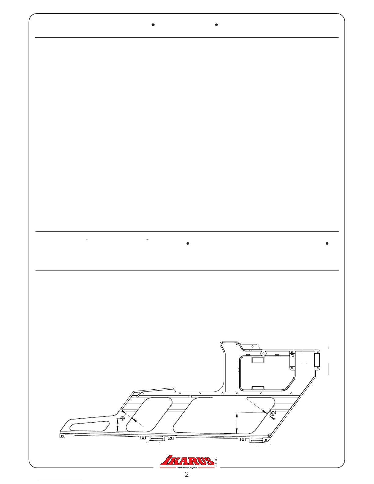
ten je 2 Bohrungen mit Durchmes-
ser 3 mm für die Kabinenhalter an
den in der Zeichnung angegebenen
Stellen. Senken Sie anschließend
die Bohrung von innen soweit
an, bis der Kopf der M3 Senkkopf-
schraube koplett versenkt ist.
with 3 mm diameter on both chassis
halves at the locations marked in the
drawing. Now carefully countersink
the holes from the inside so that the
head of the M3 countersunk head
screw can be inserted fl ush.
Dans chaque moitié de fl anc percez
2 trous de 3 mm pour la fi xation de
la verrière, à l’endroit indiqué sur le
plan. Faites un lamage jusqu’à ce
que la tête de la vis à tête fraisée M3
soit complètement noyée.
The “Bell 222” maiden fl ight was on
August 13, 1976. The serial produc-
tion started in 1978. In 1982 the Type
“Bell 222 B” with retractable landing
gear and one year later the “Bell 222
duced.
The helicopter has a 1-2 person crew
and can take a total of 7-8 persons.
The “Bell 222” is often considered as
being very elegant and found wide
spread use as “VIP Shuttle”.
please refer to the ECO 8 Royal Buil-
ding Instructions.
please follow the assembly instruc-
tions below.
Le premier vol du „Bell 222“ a eu
lieu le 13 Août 1976. Il a été lancé
en production en 1978. En 1982
une version „Bell 222 B“ avec train
rentrant a été lancée, suivie un an
après, par la version „Bell 222 UT“
avec patins.
L’équipage est composé de 1-2
pilotes, avec possibilité d’embarquer
comme appareil très élégant et sera
rapidement utilisé comme „VIP –
Pour l’utilisation et la manipulation
de l’hélicoptère, suivez les consignes
données dans la notice de l’ECO 8
Royal.
Pour le montage de la coque procédez
de la manière suivante.
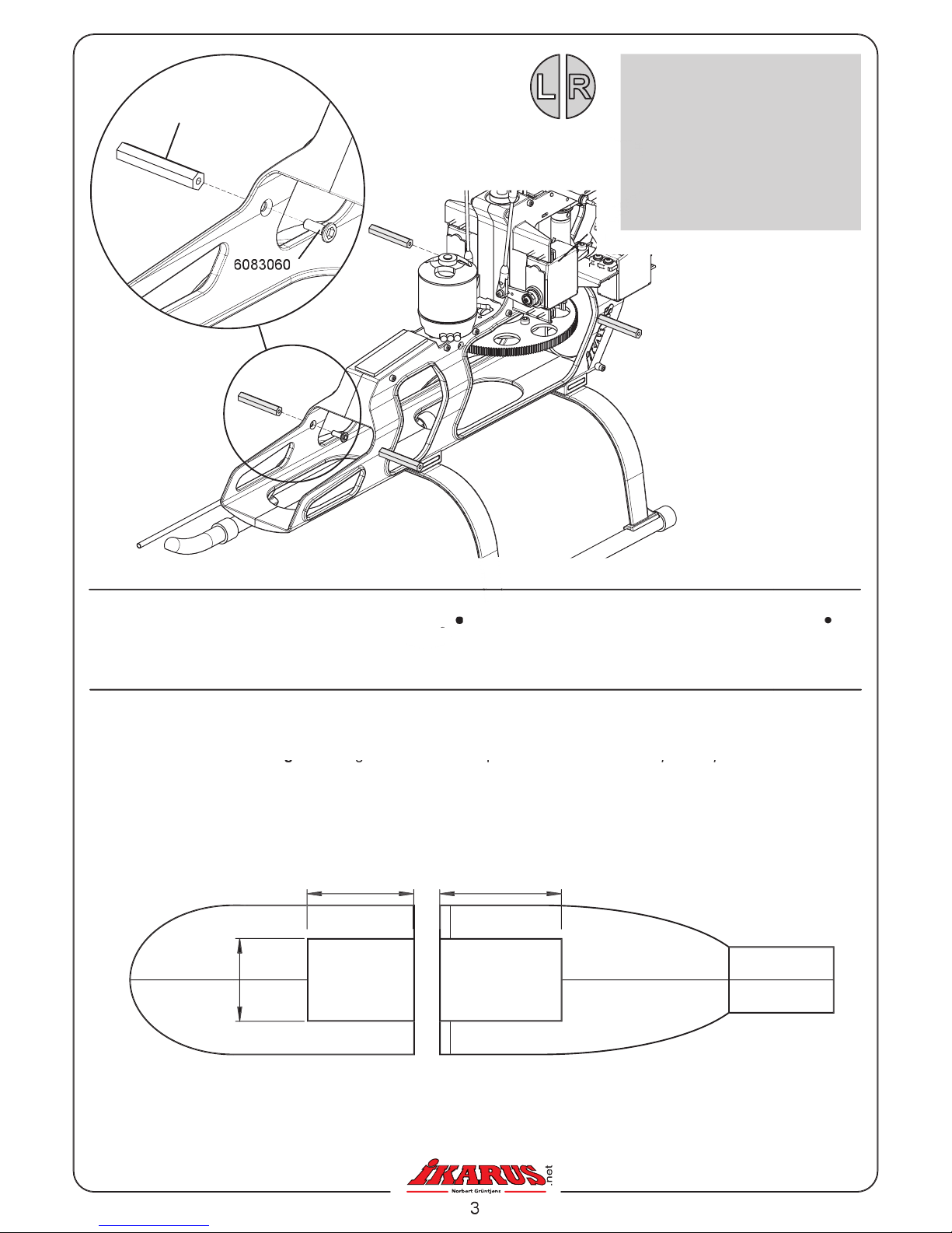
4 x 6083059
Support de verrière
4
x 6083060
B-Senkkopfschraube
M3 x 10
AH countersunk screw
M3x10
M3 x 10
6083059
Vorbereitungen am Rumpf
80 mm
9
0 mm
55
mm
Partie avant de la coque
Partie arrière (vue de dessous)
Wenn Sie anstatt des optionalen
verwenden, müssen Sie an der
sparungen ausschneiden (Siehe
gear instead of the optional retractab-
gear instead of the optional retractab-
le landing gear you will have to cut
two openings into the underside of
the fuselages (see drawing below).
classique à la place du train rentrant,
classique à la place du train rentrant,
il faudra découper dans le dessous
de la coque, deux dégagements (voir
croquis ci-dessous)

The Fuselage Rear Section
Zur Montage des Rumpfes muss der Heckrotor entfernt werden. Lösen Sie die Madenschraube, die die Heckwel-
Ø 3 x 20 mm her
aus. Der Stift
so
ehe
sichern gegen ein Verru
tschen des
Stecken Sie den Schaumstoff-Rumpfhalter direkt hinter dem Chassis auf d
as Heckrohr. Schieben Sie nun das
von
hinten auf. Richten Sie die Position aus und bohren Sie im Bereich der
je-
weils ein Loch in den
Schrauben Sie nun d
en Rumpf mit den M3 Inbusschrauben fest.
Anschließend
werden die Stummelflügel seitlich ange
klebt.
is securing the tail shaft and push out the complete tail rotor using a 3 x 20 mm pin. Leave the pin inserted, as it will
temporarily hold the belt gear in position and maintain the belt tension.
Cut the included self adhesive foam pad in half and tape these inside the rear fuselage section (see below). After
assembly these pads will be in the area of the servo mounts to prevent a shifting of the fuselage.
forward. Position the rear section correctly and drill a 3 mm hole into either fuselage side at the location of the fuselage
holders. Secure the rear fuselage section with the M3 AH screws. Now glue the two stub wings to the fuselage sides.
Pour le montage de la coque, il faut démonter le rotor arrière. Enlevez la vis qui maintient l’axe du rotor d’anti couple et
retirez le rotor complet à l’aide d’une tige (goupille) de
3 x 20 mm. Cette goupille maintient la roue d’entraînement de
la courroie en position pendant ce temps tout en maintenant en même temps la tension de la courroie.
de mousse se trouveront par la suite au niveau des supports servos et empêcheront la verrière de glisser. Montez le
support de la coque directement à l’arrière du châssis sur le tube de queue. Mettez-le en position puis percez au niveau
du support de verrière un trou dans la coque. Fixez maintenant la coque à l’aide des vis 6PC M3. Il suffi t après de coller
les deux carénages sur la coque.
6
7649
6084056
60
73115
1 x 6083056
Rumpfhalter
Schaumstoff
Support de coque
caoutchouc
1
x 6073115
Moosgummi
,
selbstklebend
Self adhesive foam pad
Mousse (autocollant)
x 6
7649
IB-Schraube M3 x 6
AH Screw M3x6

The Tail Boom Section
Schieben Sie das Heck von hinten auf bis es sauber am Rumphinterteil aufsitzt. Schieben Sie den Heckrotor wie-
der ein und sichern Sie ihn wieder mit der Madenschraube. Bohren Sie im Bereich der Löcher des Heckrotorge-
durch das Heckteil am Heckgehäuse fest. Anschließend wird das Höhenleitwerk durch das Heck geschoben und
mittig verklebt. Zum Schluss werden die zwei kleinen Seitenleitwerke am Höhenleitwerk angeklebt.
Slide on the scale tail boom from the rear until it seats correctly onto the rear fuselage section. Push the tail rotor back into
the gear box and secure it with the set screw. To attach the vertical fin drill two 2 mm holes to match the locations of the
holes in the tail gear box. Screw the M2 AH screws through the fin and the scale tail boom into the tail gear box. Now slide
the horizontal stabilizer through the scale tail boom, center it and glue it on. Finally glue on the two small vertical fins.
Montez tout l’anti couple par l’arrière sur la partie arrière de la coque et positionnez-la correctement. Remontez le rotor
arrière et fixez l’axe de nouveau avec la vis sans tête. Au niveau du boîtier
anti couple, percez deux trous de 2 mm de diamètre. Avec les deux vis 6PC M2, fixez la dérive sur le boîtier de l’anti
couple. Passez ensuite le stabilisateur au travers de la poutre, puis collez-le.
Les deux petits ailerons sont ensuite collés de part et d’autre du stabilisateur.
2 x 67547 Heckrotorblatt
1 x 6083057
Seitenleitwerk groß
Vertical Stabilizer
x 6084058 Seitenleitwerke klein
Vertical Stabilizer, small
Ailerons
Ersetzen Sie die Heckrotorblätter durch
das im Bausatz enthaltene Rotorblattpaar.
rotor blades included in the kit.
Remplacez les pales du rotor arrière par
la paire de pales fournie dans la boîte de
construction.
60
84058
60
840
62
60
84058
60
84057
60
540
75
6
7547
x 6
054075
IB-Schraube M2 x 8
AH Screw M2x
8
2
x 6084062 Höhenleitwerk
Stabilisateur

The Fuselage Front Section
2
x 6
7649
IB-Schraube M3 x 6
AH Screw M3x6
Schieben Sie das Rumpfvorderteil
au
f. Richten Sie die Position aus und bohren Sie im Bereich der
jeweils ein Loch in den
Schrauben Sie nun d
en Rumpf mit den M3 Inbusschrauben fest. Zur zu-
sätzlichen Fixierung empfehlen wir, Rumpfvorder- und -hinterteil mit einem Stück Klebestreifen oder Klettband
miteinander zu befestigen.
Slide the front section over the front mechanics. Position it correctly and drill a 3 mm hole into each side to exactly match
the location of the front fuselage holders. In addition we recommend connecting the fuselage front and rear section to
each other with self adhesive tape or hook-and-loop tape. Finally decorate the fuselage with the included decals.
Montez la partie avant de la coque. Positionnez-la puis percez un trou au niveau du support de la verrière. Fixez main-
tenant la coque avec le vis 6PC M3. Pour un meilleur maintien de la partie avant sur la partie arrière, nous vous conseil-
lons de maintenir ces deux parties avec un morceau de ruban adhésif supplémentaire.
Il ne vous reste plus qu’à poser la décoration (planche de décoration fournie).
6
7649

ür dieses IKARUS Produkt übernehmen wir eine Gewährleistung von 24 Monaten. Als Beleg für den Beginn und den
Ablauf dieser Gewährleistung dient die Kaufquittung. Eventuelle Reparaturen verlä
ngern den Gewährleistungszeitraum
nicht. Wenn im Garantiezeitraum Funktionsmängel, Fabrikations- oder Materialfehler auftreten, werden diese von uns
behoben. Weitere Ansprüche, z. B. bei Folgeschäden, sind komplett ausgeschlossen. Reparatureinsendungen bitte an
die unten angegebene Adresse. Bei Einsendung eines Gerätes, das sich nach der Eingangsprüfung als funktionsfähig
herausstellt, erheben wir eine Bearbeitungsgebühr von 20,- €. Der Transport muss frei erfolgen, der Rücktransport erfolgt
ebenfalls frei. Unfreie Sendungen können nicht angenommen werden. Für Schäden, die beim Transport Ihrer Zusendung
erfolgen, übernehmen wir keine Haftung. Auch der Verlust Ihrer Sendung ist von der Haftung durch uns ausgeschlos-
sen.
(
0,99 €/ Min.
von 14 Uhr bis 16 Uhr).
Warranty terms
We warrant the IKARUS product within the European Union for a period of 24 months.
Your sales receipt is evidence of the start and fi nish of the warranty period. Any repairs do not extend the warranty peri-
od. If any functional, manufacturing or material defects become evident during the warranty period we will rectify them.
shipping charges) for repair items, which turn out to be in perfect condition. Postage must be paid for; the return shipping
will also be paid for. Shipments arriving postage collect will not be accepted. We do not accept any liability for damage
or loss during inbound transport.
karus‘ warranty policy on Products:
or workmanship and to operate as advertised for a period of 60 days from the time of its original purchase. Hobby Lobby
will replace the product at no charge except for return postage. Damage caused by modifi cation, misuse, and crashes
is not covered under this warranty.
Once opened fl ight simulators are not eligible for return. Read and know
the system requirements before opening the fl ight simulator. If you experience any problems please contact Hobby Lobby
Conditions de garantie
garantie. D’éventuelles réparations ne prolongent pas cette durée. Si pendant cette période, des défauts matériels ou de
fabrication ainsi que des ratés au niveau fonctionnel surviennent, nous les réparerons. Tout autre problème comme par
ex. des dégâts consécutifs ne sont pas couverts. Envoyez l’article défectueux à l’adresse indiquée. Votre envoi doit être
affranchi par vos soins, de même que l’envoi de retour le sera par nos soins. Tout article retourné pour réparation dont le
fonctionnement s’avère correct après contrôle, fera l’objet d’une facturation forfaitaire de 20,- €. Les envois non affran-
chis ne peuvent pas être acceptés. Nous ne sommes pas responsables des dommages survenant pendant le transport
de votre paquet. De même en cas de perte du colis. Pour toute réclamation ou commande de pièces de rechange, veuil-
lez contacter l’une des adresses suivantes.
www.ikarus.net
D-78713 Schramberg-Waldmössingen
Bestellhotline: +49 (0) 74 02/ 92 91-900
Service:
(0,99 €/Min.)
0 900 1/ 79 50 20
Fax: +49 (0) 74 02/ 92 91-750
info@ikarus.net
57, Rue de Phalsbourg
67260 Sarre-Union
Tél: +33 (0) 388 01 10 10
Fax: +33 (0) 388 01 11 12
info@ikarus-france.com
Hobby Lobby International
5614 Franklin Pike Circle
Brentwood, TN 37027
Phone: 866-933-5972
sales@hobby-lobby.com
 Loading...