

Page 1
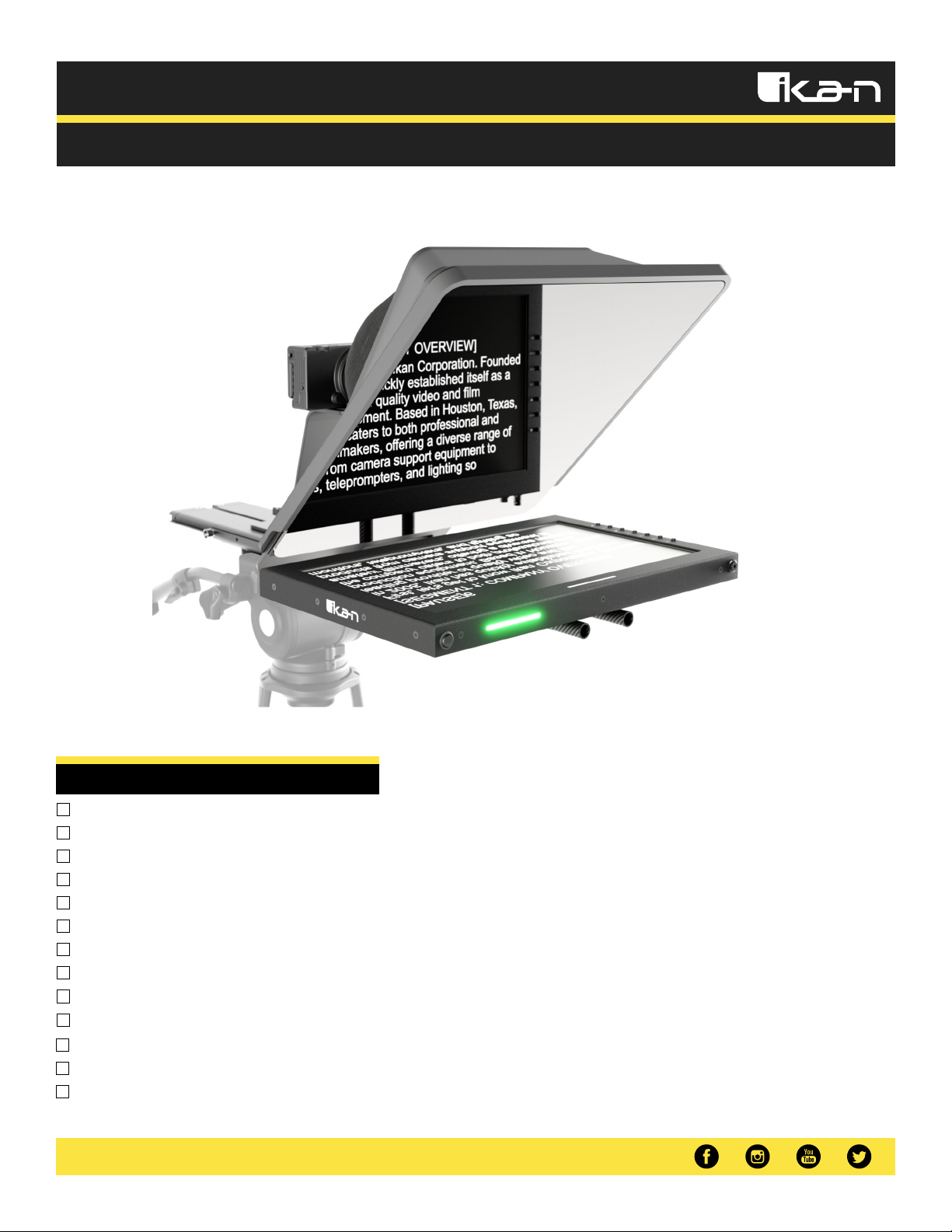
Quick Start Guide
PT4500W
Professional 15″ High Bright Teleprompter with 3G-SDI Widescreen Monitor
What’s Included
1x Teleprompter Base
1x Hood Frame
1x Silicone Hood w/ Canvas Shroud
1x Counterweight
1x Tall Riser
1x Medium Riser
1x DSLR Riser
2x L-Shaped Hex Keys
2x 1/4-20 Camera Screws
1x 15 in. Widescreen Monitor
1x Power Adapter
1x 70/30 15 in. Glass
1x Digital Copy of Prompter Pro4
www.ikancorp.com| 1.713.272.8822 | [email protected]
Page 2
Teleprompter Assembly Setup
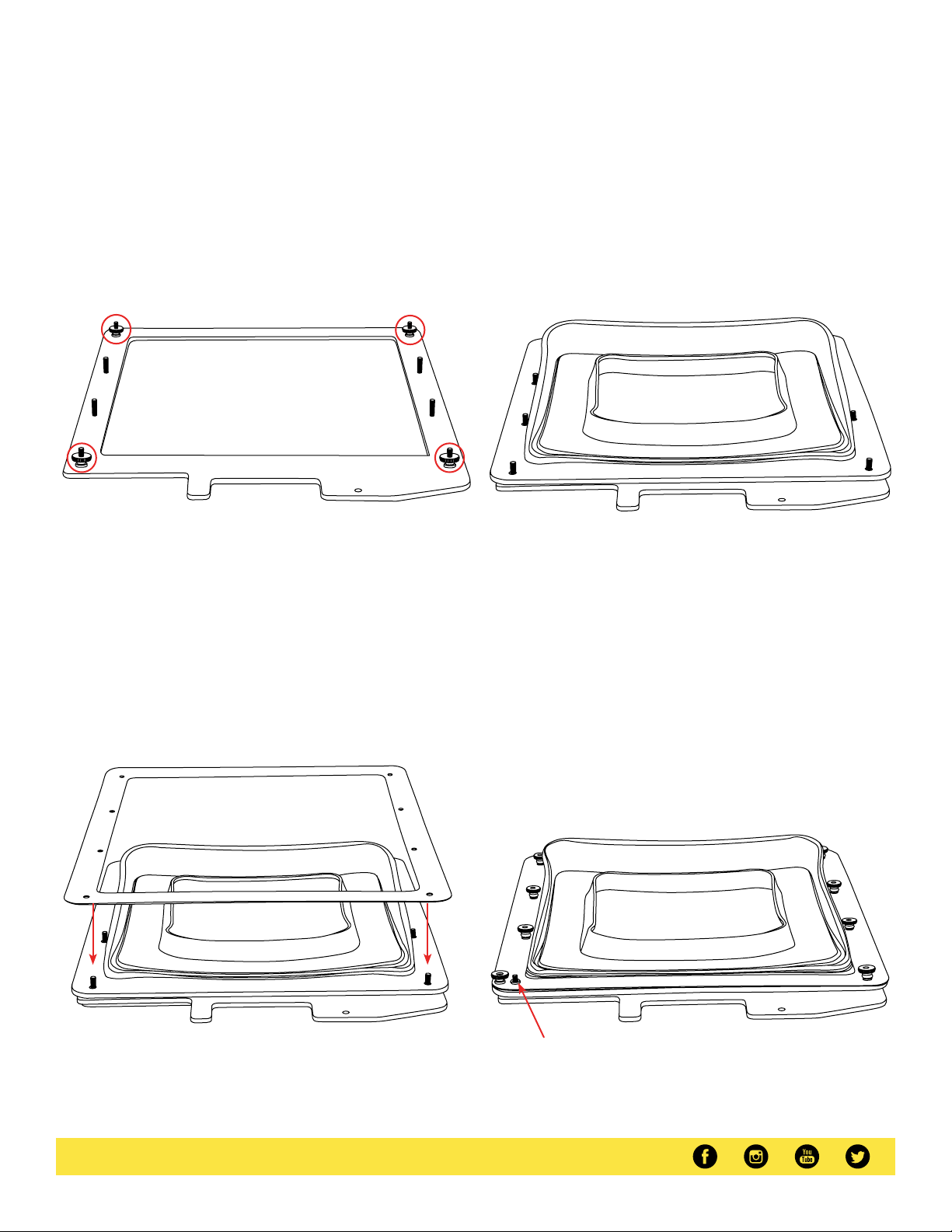
Step 1
Place the teleprompter glass frame on a flat surface and remove the four
screws as shown.
Step 3
The metal frame is directional. Make sure the thicker side is on top and
the slimmer side is on the bottom.
Step 2
Align and attach the teleprompter hood with the 8 screw pegs from the
teleprompter frame.
Step 4
Put the washers on before tightening the screws. The washers and 4
additional screws are inside a bag on the bottom foam.
www.ikancorp.com| 1.713.272.8822 | [email protected]
Page 3
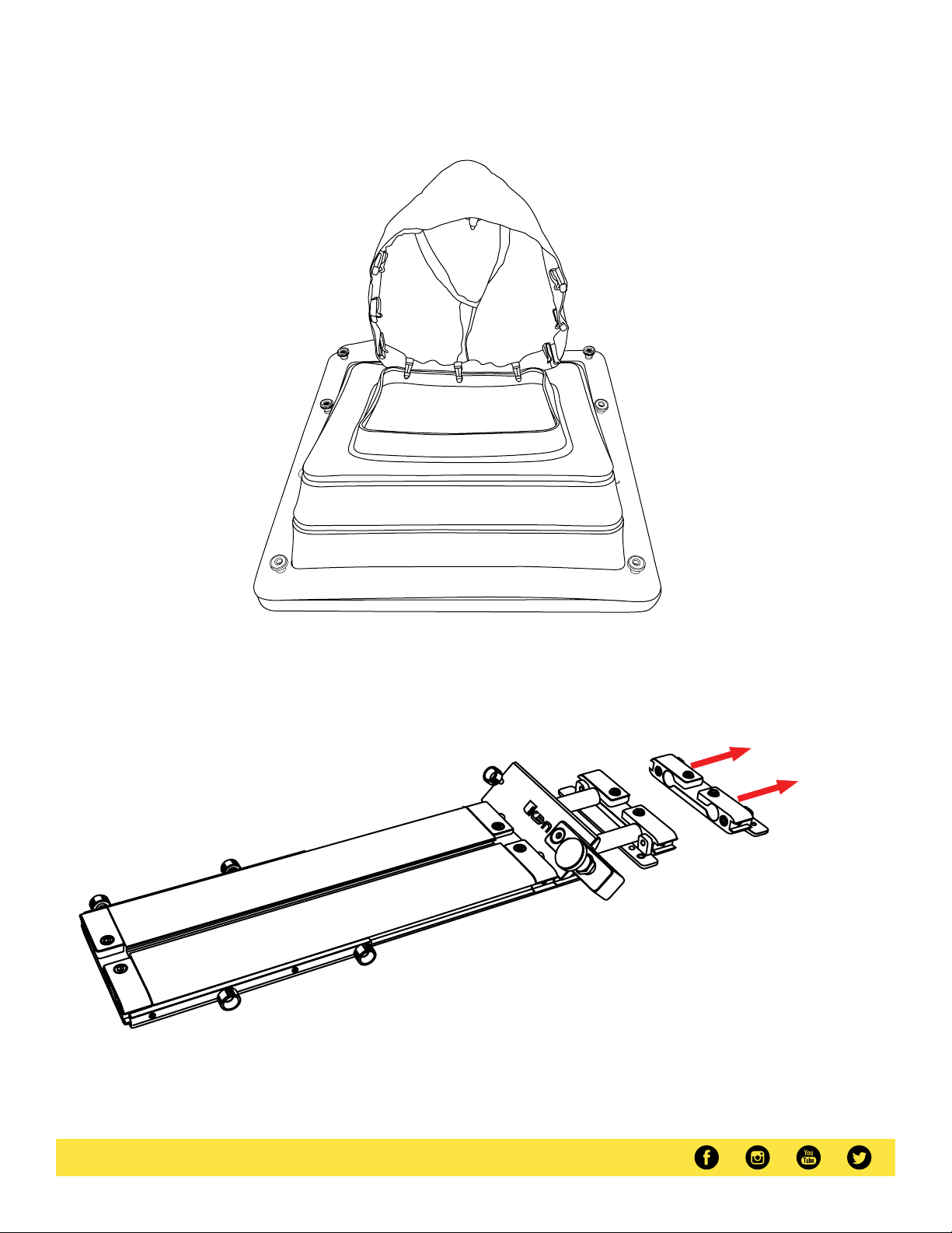
Step 5
Extendthe teleprompter hood open and attach teleprompter boot using the clips. Itis suggested to align theseamwith the bottomof the teleprompter hood.
Step 6
Removethe monitor mounts from the teleprompter base using the included larger 4mm hex keyto loosen from the 15mm rods.
www.ikancorp.com| 1.713.272.8822 | [email protected]
Page 4
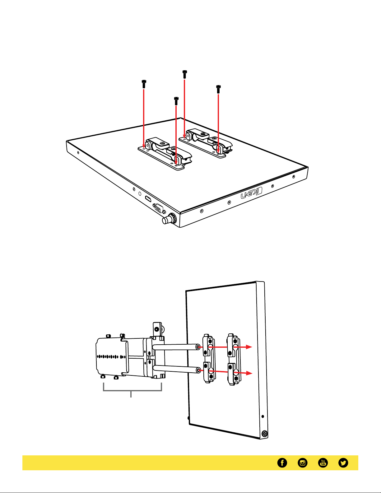
Step 7
Attach the monitor mounts on the back of the monitor’s VESA compatible threads using the 4 included screws and provided 2mm hex key.
V
4
2
-
2
1
I
M
D
H
A
G
V
AV
Step 8
After the monitor mounts are attached, adjust the 15mm rods to accommodate the monitor. Leave about 1 inch of room for the teleprompter bracket.
Make sure the 15mm rods go through both set of monitor mounts. Please ensure that all screws are properly tightened after inserting the monitor.
*SAFETY NOTE* Make sure to leaveat least 2 inches of the rods inside the teleprompter base.
Teleprompter Base
www.ikancorp.com| 1.713.272.8822 | [email protected]
Page 5
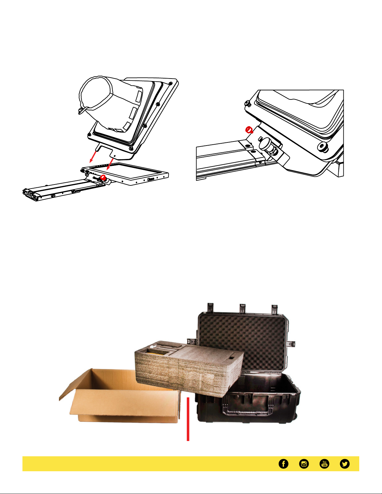
Step 9
While sliding the teleprompter bracket into the slot of the teleprompter
base pull on the red knob to allow the bracket to fully slide in.
Step 10
Once the bracket is in place,tighten the side screw to lock in place. Double
check and make sure all the screws are tightened with the included hex
keys.
Step 11 (optional)
Should the teleprompter be too front heavy, you can attach the included counter weight on the back of the teleprompter base.
Foam Case
To make your teleprompter more portable, we packed it in a reusable, high-quality foam.
The shape and size of the foam was designed to fit into Ikan’s PT-CASE-V2.
** DO NOT THROW AWAY FOAM CASE**
www.ikancorp.com| 1.713.272.8822 | [email protected]
Page 6
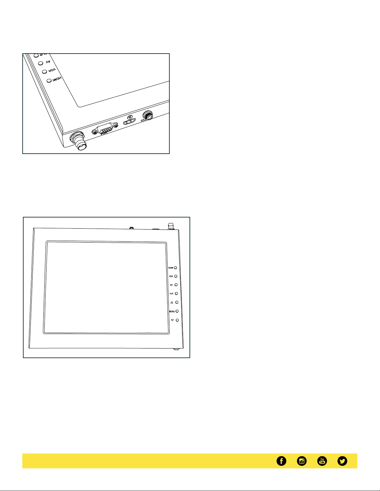
Monitor Ports
HDMI
BNC– SDI Input
VGA– Video Graphics Array DE15 Connection
HDMI– High-Definition Multimedia Interface Input Connection
Power Port – 12-24v Input
Monitor Menu Settings
Video Config
Contrast (White Level)
Brightness (Black Level)
Tint (Chroma Hue)
Chroma (Chroma Saturation)
Sharpness (Detail)
RGBSetup – Manually configure RGB
Return
System Config
Menu Duration – Set duration of how long menu stays
on screen
VideoRatio– Set screen aspect ratio 16:9 or 4:3 (4:3 is
native resolution,16:9 will create black bars)
Flip-H – Assign toggle button to flip image horizontally
Flip-V – Assign toggle button to flip image vertically
Reset – Factory reset
Return
PC Setup (Only available for VGA)
H-Position – Adjust horizontal position
V-Position – Adjust vertical position
Auto – Monitor automatically adjust position
Return
Exit
HDMI– Switch HDMI input
VGA– Switch to VGA input
SDI – Switch to composite SDI input
Flip – Toggle image flip
(Canbe set to horizontal, vertical, or both via menu)
UpArrow – Toggle up to adjust setting
Menu – Access to monitor settings
Down Arrow – Toggle down to adjust setting
How to set-up FLIP button feature:
1. Press MENUbutton
2. Navigate to SYSTEM CONFIG.
3. Navigate to FLIP-V or FLIP-H
4. Change FLIP-Vand/or FLIP-H to “ON”
5. Exit MENU
6. The FLIP button should now be activated and can be
pressed to mirror the image Horizontally or Vertically
7. When FLIP-His ON, the image will flip Horizontally
8. When FLIP-Vis ON,the image will flip Vertically
9. If both are ON, the FLIP button will toggle both
Horizontal and Vertical flip
www.ikancorp.com| 1.713.272.8822 | [email protected]
Page 7
Watch our VIDEO TUTORIAL on how to assemble Ikan Professional Teleprompters:
ikancorp.com/15-in-videos/
Specifications
15 in. Teleprompter 15 in. Teleprompter Monitor
Riser Plate Height Aspect Ratio
Length of Rods Maximum Brightness15mmx 400mm 1000cd/m2
Build Material Screen Size (Diagonal)
Reading Range Tally Input17 ft./5.18m RJ45
Beamsplitter Ratio Tally Pin out70/30 3-Pin (5V, Red GND, Green GND)
Beamsplitter Shape MountRectangular VESA100mm
Beamsplitter Material Video InputsGlass SDI, HDMI, VGA
Tripod Mounts Input Voltage
Product Weight w/ Low Plate
Product Weight w/ Medium Plate
Product Weight w/ High Plate
Weight Native Resolution22 lb 1920 x 1080
Product Weight w/ DSLR Plate
Sliding Range Build Material
Medium: 3.74 in.| High: 5.31 in./ | DSLR: 6.29
in./160mm
Chassis: Anodized Aluminum | Rods: Carbon Fiber
8 x 1/4 in . -20 Female | 6 x 3/8 in. -16 Female
Power Consumption24.11 lbs. 26.5W
Product Weight24.51 lbs. 3.73 lbs.
Product Dimensions24.64 lbs. 15.7 x 10.6 x 1.1 in.
ViewingAngle24.01 lbs. 178° (H) / 178° (V)
5.9 in./150 mm Aluminum Chassis
Image Flip
16:9
15 in.
DC 12v
Horizontal: Yes | Vertical: Yes
Optional Accessories
PT4500-G
M15W
PT15-SDI-V2
PT-CASE-V2
PT-CASE-15TM
www.ikancorp.com| 1.713.272.8822 | [email protected]
Replacement Glass for both PT4500-V2
15” High Bright Widescreen Talent Monitor (for PT4500-SDI-V2)
15” High Bright 4:3 Monitor (for PT4500-SDI-V2)
Rolling HardCasefor PT4500-SDI-V2 Teleprompter
Hard Case for 15" Talent Monitor
Page 8

Supported Video Signals
SDI & HDMI:
10 80p @ 5 0, 25, 59.94, 60 , 23 .976, 24, 29.97 , 30 Hz
10 80i @ 5 0, 59. 94, 60 Hz
72 0p @ 50 , 59 .94, 60 H z
48 0p @ 59 .94 Hz
57 6p @ 50 , 59 .94 Hz
57 6i @ 50 Hz
19 20x1200 @ 60 Hz
16 00 x 12 00 @ 60 Hz
14 00x1050 @ 60 Hz
12 80x1024 @60 Hz
12 80x960 @ 60 H z
13 60x768 @ 60 H z
12 80x768 @ 60 H z
10 24x768 @6 0 Hz
80 0x600 @ 6 0 Hz
64 0x480 @ 6 0 Hz
Learn More
More dynamic information at official website: www.ikancorp.com
Support
Contact email: [email protected]
CONDITIONS OF WARRANTY SERVICE
• Freeservice for one yearfrom the day of purchase if the problem is caused by manufacturing errors.
• The components and maintenance servicefee will be charged if the warranty period is expired.
Free Service will not be Provided in the Following Situations:(*Even if the product is still within the warranty period.)
• Damagecaused by abuse or misuse, dismantling, or changes to the product not made by the company.
• Damagecaused by natural disaster, abnormal voltage, and environmental factors, etc.
©2024 Ikan International.All rights reserved.
www.ikancorp.com| 1.713.272.8822 | [email protected]
Page 9
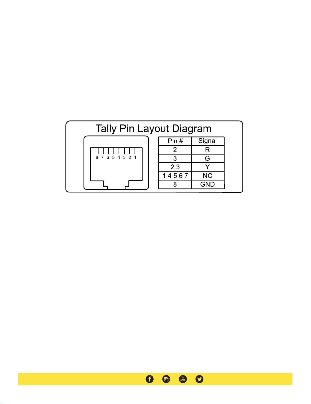
Pinout Diagram for Tally Light
Tally LightPinout:
GND: Connects to the ground of the device or system.
R: Connects the red tally light
G: Connects the green tally light
Y: Connects the yellow tally light
NC: Stands for"Not Connected"Disregard these pins.
Learn More
More dynamic information at official website :www.ikancorp.com
Support
Contact email: [email protected]
©2024 Ikan International.All rights reserved.
www.ikancorp.com|1.713.272.8822|[email protected]
 Loading...