

Page 1
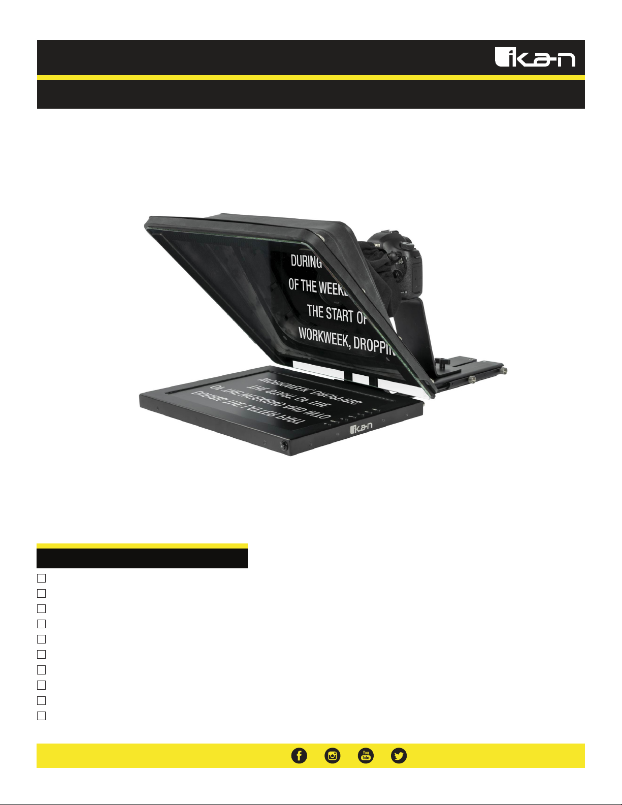
Quick Start Guide
PT4500-SDI / PT4700-SDI
High Bright Beam Splitter Teleprompter w/ 3G-SDI, HDMI, & VGA
What’s Included
1 x Teleprompter Base
1 x Bracket with Glass
1 x Teleprompter Hood with Boot
1 x Monitor
1 x AC Adapter with Cord
1 x PrompterPro Software
1 x Counterweight Set (2 x 2.5 lbs)
2 x D-Ring ¼-20” Screws
2 x Hex Keys
3 x Different Height Risers
Page 2
Teleprompter Assmebly Setup
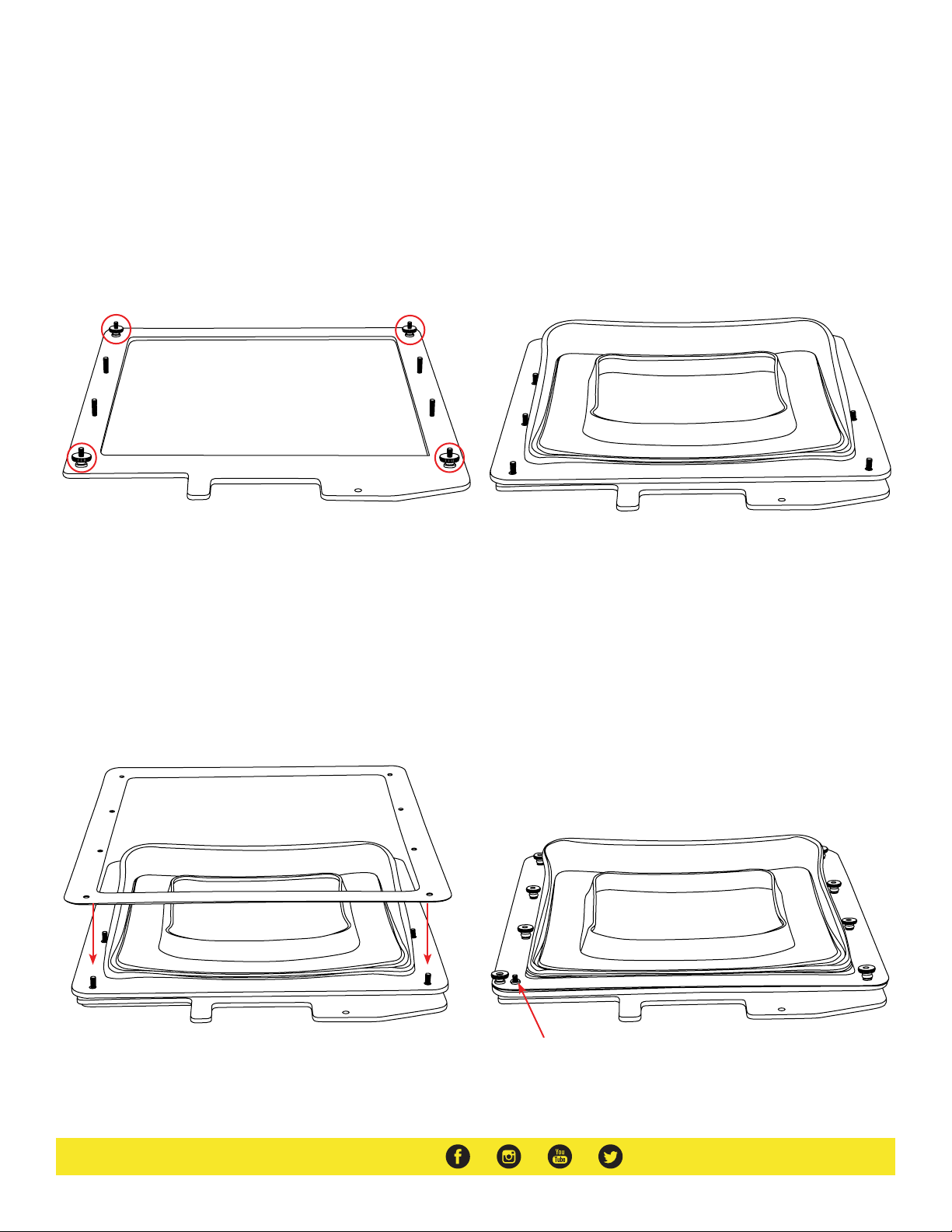
Step 1
Place the teleprompter glass frame on a flat surface and remove the four
screws as shown.
Step 3
The metal frame is directional. Make sure the thicker side is on top and
the slimmer side is on the bottom.
Step 2
Align and attach the teleprompter hood with the 8 screw pegs from the
teleprompter frame.
Step 4
Put the washers on before tightening the screws. The washers and 4
additional screws are inside a bag on the bottom foam.
Page 3
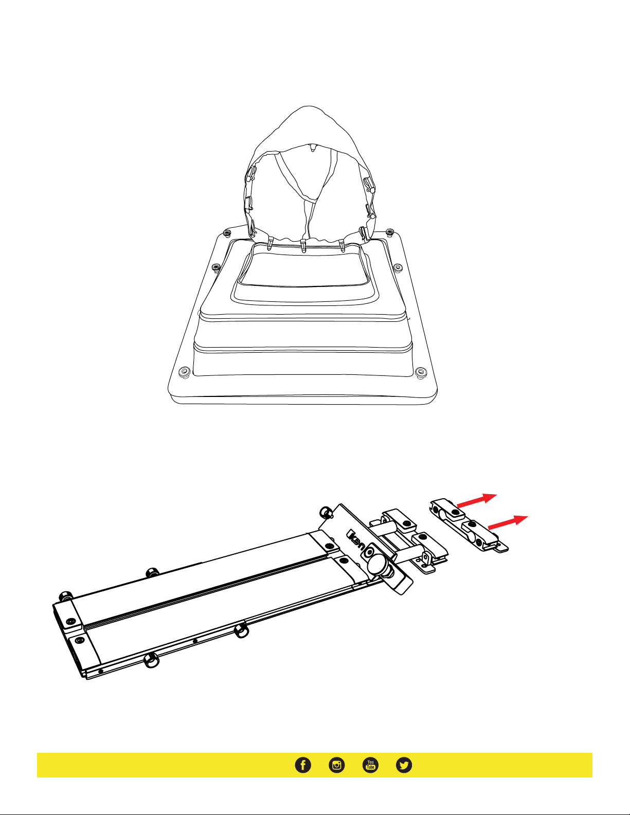
Step 5
Extend the teleprompter hood open and attach teleprompter boot using the clips. It is suggested to align the seam with the bottom of the teleprompter hood.
Step 6
Remove the monitor mounts from the teleprompter base using the included larger 4mm hex key to loosen from the 15mm rods.
Page 4
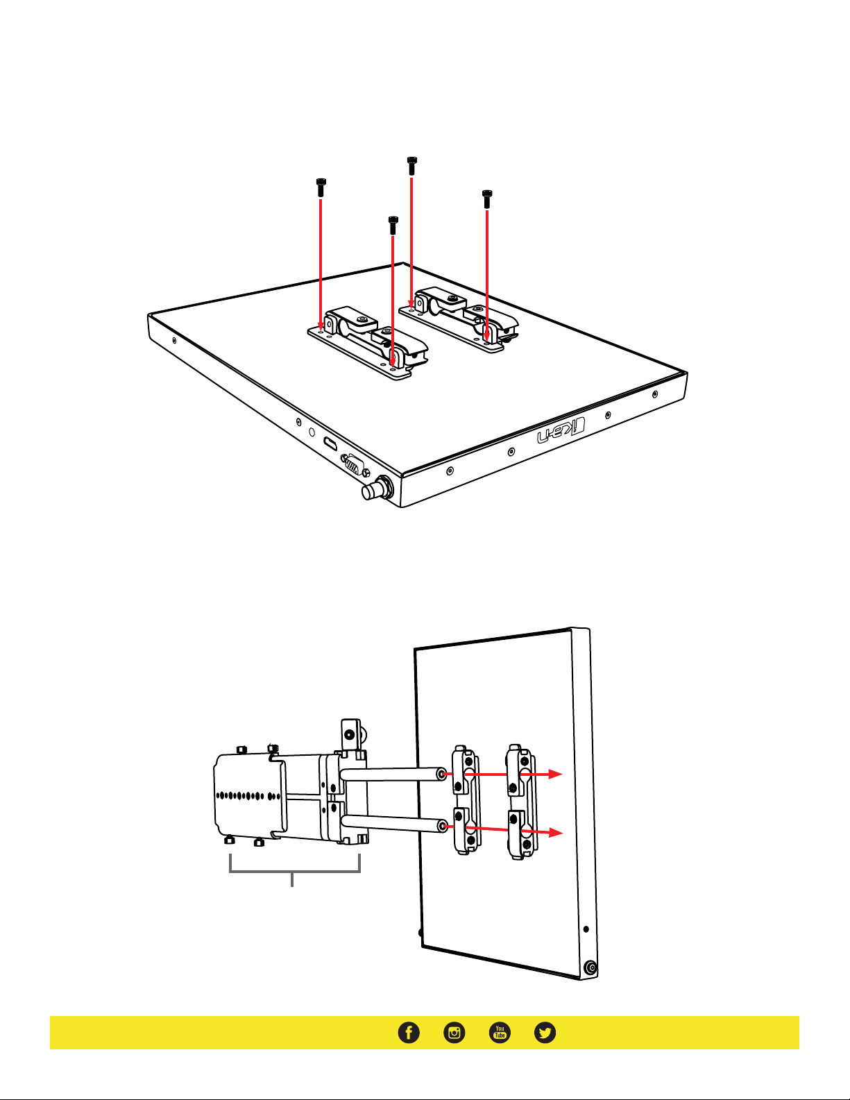
Step 7
Attach the monitor mounts on the back of the monitor’s VESA compatible threads using the 4 included screws and provided 2mm hex key.
V
4
2
-
2
1
I
M
D
H
A
G
V
AV
Step 8
After the monitor mounts are attached, adjust the 15mm rods to accommodate the monitor. Leave about 1 inch of room for the teleprompter bracket.
Make sure the 15mm rods go through both set of monitor mounts. Please ensure that all screws are properly tightened after inserting the monitor.
*SAFETY NOTE* Make sure to leave at least 2 inches of the rods inside the teleprompter base.
Teleprompter Base
Page 5
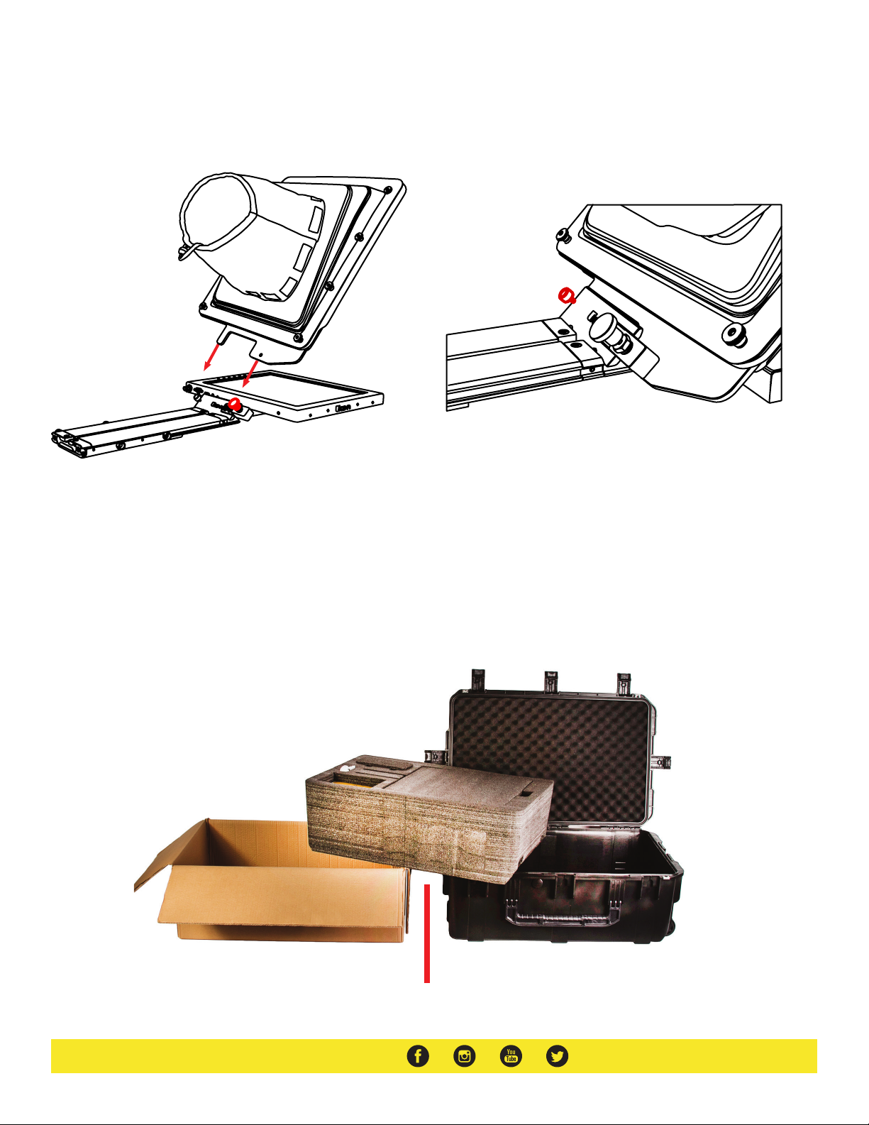
Step 9
While sliding the teleprompter bracket into the slot of the teleprompter
base pull on the red knob to allow the bracket to fully slide in.
Step 10
Once the bracket is in place, tighten the side screw to lock in place. Double
check and make sure all the screws are tightened with the included hex
keys.
Step 11 (optional)
Should the teleprompter be too front heavy, you can attach the included counter weight on the back of the teleprompter base.
Foam Case
To make your teleprompter more portable, we packed it in a reusable, high-quality foam.
The shape and size of the foam was designed to fit into Ikan’s PT-CASE-V2.
** DO NOT THROW AWAY FOAM CASE **
Page 6
Watch our VIDEO TUTORIAL on how to assemble Ikan Professional Telepromopters:
https://youtu.be/5TjIxzBc_Vc
Specifications
PT4500-SDI PT4700-SDI
Aspect Ratio 4:3
Backlight LED
Brightness 1000 nits
Build Material Aluminum
Diagonal 15”
Input Signal 3G-SDI, VGA, HDMI
Input Voltage DC 12v / 4A
Power Consumption 10W
Reading Range 17’
Resolution 1280 x 1024
Viewing Angle 160° (H) / 170° (V)
Weight 22 lb
Shipping Weight 28 lb
Shipping Dimensions 25 x 20 x 15.5 in
Aspect Ratio 4:3
Backlight LED
Brightness 1000 nits
Build Material Aluminum
Diagonal 17”
Input Signal 3G-SDI, VGA, HDMI
Input Voltage DC 12v / 4A
Power Consumption 10W
Reading Range 20’
Resolution 1280 x 1024
Viewing Angle 160° (H) / 170° (V)
Weight 23 lb
Shipping Weight 29 lb
Shipping Dimensions 25 x 20 x 15.5 in
Optional Accessories
PT4500-G
PT-CASE-V2
Replacement Glass for both PT4500-SDI / PT4700-SDI
Rolling Hard Case for PT4500-SDI / PT4700-SDI Teleprompter
Page 7
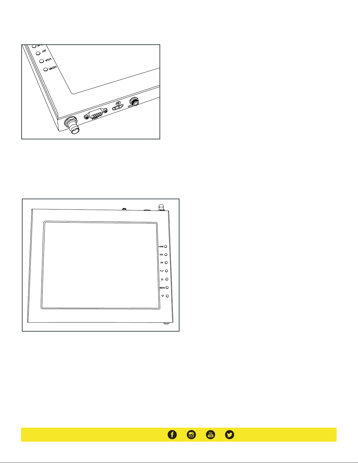
Monitor Ports
H
D
M
I
3G-SDI – Serial Digital Interface Connection
VGA – Video Graphics Array DE15 Connection
HDMI – High-Definition Multimedia Interface Input Connection
Power Port – 12-24v Input
Monitor Menu Settings
Video Config
Contrast (White Level)
Brightness (Black Level)
Tint (Chroma Hue)
Chroma (Chroma Saturation)
Sharpness (Detail)
RGB Setup – Manually configure RGB
Return
System Config
Menu Duration – Set duration of how long menu stays
on screen
Video Ratio – Set screen aspect ratio 16:9 or 4:3 (4:3 is
native resolution, 16:9 will create black bars)
Flip-H – Assign toggle button to flip image horizontally
Flip-V – Assign toggle button to flip image vertically
Reset – Factory reset
Return
PC Setup (Only available for VGA)
H-Position – Adjust horizontal position
V-Position – Adjust vertical position
Auto – Monitor automatically adjust position
Return
Exit
HDMI – Switch HDMI input
VGA – Switch to VGA input
SDI – Switch to 3G-SDI input
Flip – Toggle image flip
(Can be set to horizontal, vertical, or both via menu)
Up Arrow – Toggle up to adjust setting
Menu – Access to monitor settings
Down Arrow – Toggle down to adjust setting
How to set-up FLIP button feature:
1. Press MENU button
2. Navigate to SYSTEM CONFIG.
3. Navigate to FLIP-V or FLIP-H
4. Change FLIP-V and/or FLIP-H to “ON”
5. Exit MENU
6. The FLIP button should now be activated and can be
pressed to mirror the image Horizontally or Vertically
7. When FLIP-H is ON, the image will flip Horizontally
8. When FLIP-V is ON, the image will flip Vertically
9. If both are ON, the FLIP button will toggle both
Horizontal and Vertical flip
Page 8
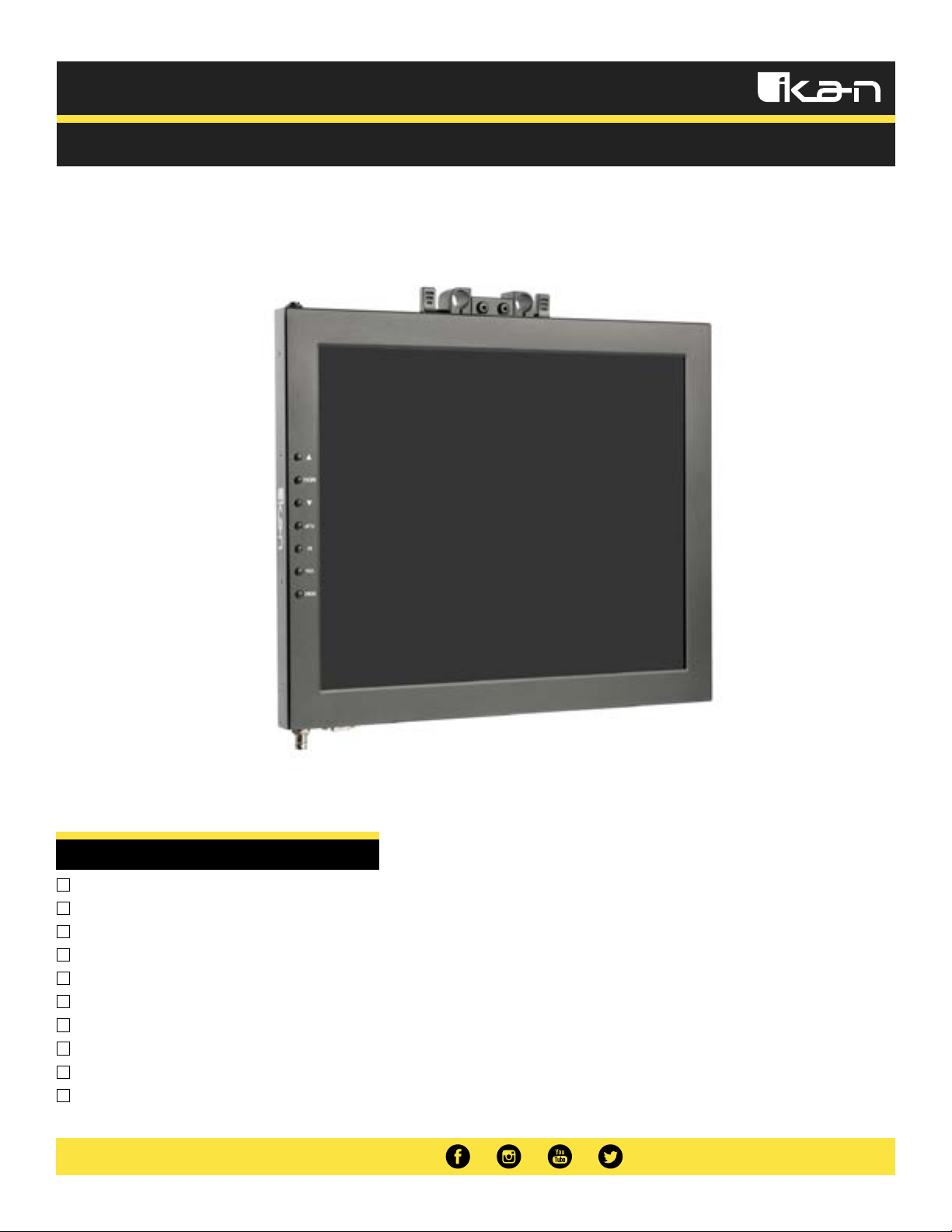
Quick Start Guide
PT15-SDI-TM / PT17-SDI-TM
Talent Monitor Add On Kit for PT4500-SDI / PT4700-SDI
What’s Included
1 x Teleprompter Monitor
1 x Power Adapter with Cable
1 x VESA Monitor Mount
1 x 15mm Rod Adapter
1 x Mounting Knob
4 x 10mm Screws
4 x 15mm Screws
2 x Large Screws
4 x Riser Washers
1 x Adjustable Plate
Page 9
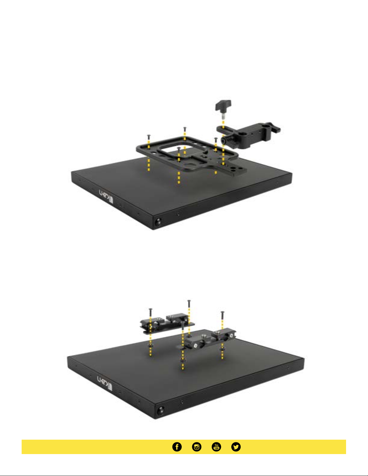
Assembly Steps
Setting Up the Talent Monitor
Using the shorter 4 x 10mm Screws, attach the VESA Monitor Mount. Make sure that the long end of the VESA Monitor Mount is pointing in the direction
of the power button like the image above. Use the Mounting Knob to tighten the 15mm Rod Adapter to the VESA Monitor Mount.
Setting Up the Teleprompter Monitor (Monitor from the PT4500-SDI/PT4700-SDI)
If the mounting brackets where previously installed on the teleprompter monitor, remove those screws. Using the longer 4 x 15mm Screws and 4 x Riser
Washers attache the mounting brackets with the washers between the bracket and monitor like the image below.
Page 10
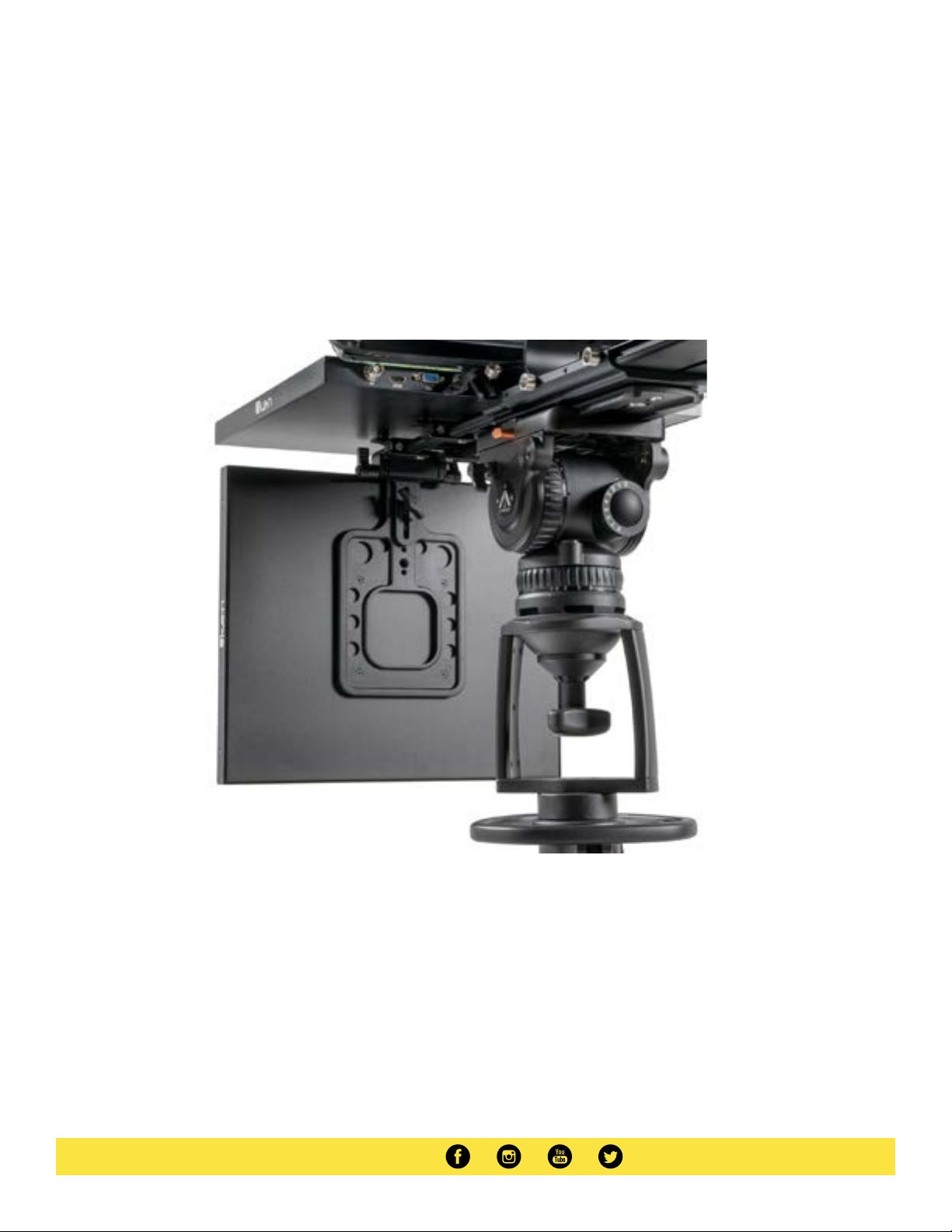
Attaching the Talent Monitor
After both the talent monitor and teleprompter monitor are set up, slide the talent monitor on to the PT4500-SDI/PT4700-SDI.
*WARNING* We recommend at least 1 inch of rod should be left inside the teleprompter base.
Page 11
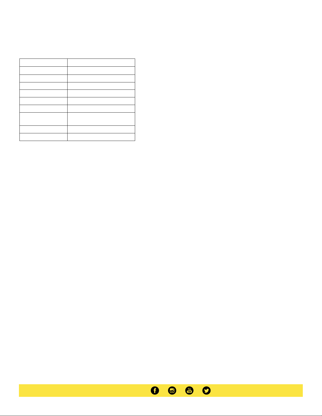
Specifications
Aspect Ratio 4:3
Backlight LED
Brightness 1000 nits
Build Material Aluminum
Input Signal 3G-SDI, VGA, HDMI
Input Voltage DC 12V - 24V
Color Systems PAL/NTSC/SECAM (Auto-Detected)
Screen Resolution
Shipping Dimensions 15 x 12 x 4 in.
Shipping Weight 6 lbs
15”: 1280 x 1024
17”: 1280 x 1024
Optional Accessories
Some other products that work well with this item available from Ikan include:
PT4500-SDI
PT4700-SDI
15” High Bright Beam Splitter Teleprompter (
3G-SDI, VGA, HDMI)
17” High Bright Beam Splitter Teleprompter (3G-SDI, VGA, HDMI)
Page 12

Learn More
More dynamic information at official website: www.ikancorp.com
Support
Contact email: [email protected]
CONDITIONS OF WARRANTY SERVICE
• Free service for one year from the day of purchase if the problem is caused by manufacturing errors.
• The components and maintenance service fee will be charged if the warranty period is expired.
Free Service will not be Provided in the Following Situations:(*Even if the product is still within the warranty period.)
• Damage caused by abuse or misuse, dismantling, or changes to the product not made by the company.
• Damage caused by natural disaster, abnormal voltage, and environmental factors, etc.
©2020 Ikan International. All rights reserved.
 Loading...