

Page 1
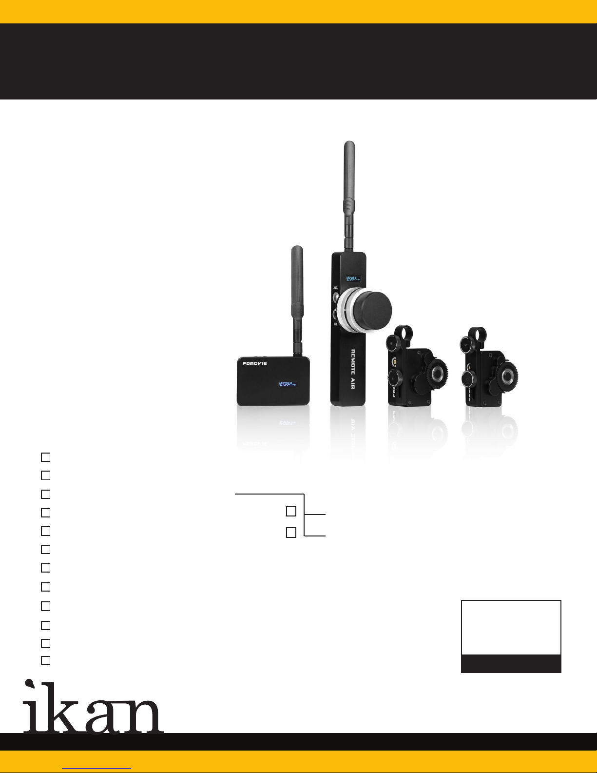
QUICKSTART GUIDE
PD2 & PD2-HT
Remote Air Follow Focus System / High Torque System
What’s Included
1 x Wireless Remote
1 x Receiver/Motor Controller
1 x Follow Focus Motor
1 x P-Tap Power cord
1 x USB Charging Cable
2 x Motor Drive Line
1 x USB Wall Port
1 x Strap
2 x Antenna
2 x Short Antenna
3 x 15–19mm Adapter Rings
1 x Hard Case
Standard
High Torque
CHECKED BY
www.ikancorp.com
713.272.8822
Page 2
Welcome to your New PD Movie
Remote Follow Focus System
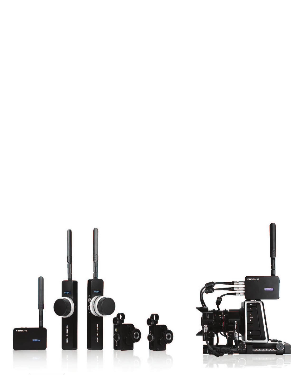
Welcome to Ikan’s PD Movie Remote Air Follow Focus System. You will find that this and other
PD Movie products have been created with the objective of expanding your image capture options and enabling you to adapt to a variety of shooting scenarios. Being modular in design, there
are alternative ways of configuring the equipment to change your control surfaces, mounts, and
power options, and add control features to meet your camera and rig needs.
PD Movie Remote Air Models PD1 and PD2 — whether the Standard Torque or High Torque
versions — will accurately control your lens and camera wirelessly. You will need to provide a prostyle battery (Sony V-Mount or Anton Bauer) or power source of 12-20V from a P-Tap to power
your receiver and the motors. There are optional coax to Lemo power plug options available from
your Ikan dealer. www.Ikancorp.com
Page 3
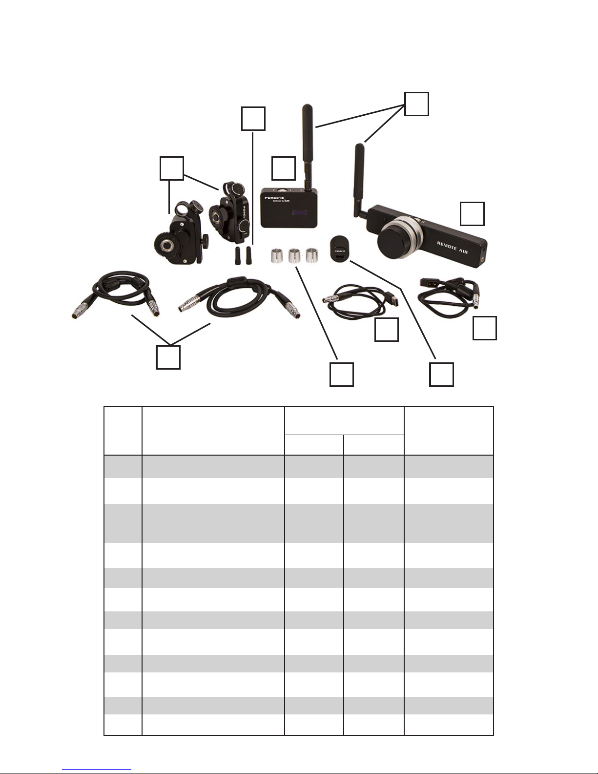
What’s Included
J
I
NO
F
C
Name
B
Single Channel
EF
J
(Focus)
MAX
E
A
D
G
Dual Channels
(Focus, Zoom)
A
B
C
D
E
F
G
H
I
J
K
L
Wireless Remote
Receiver/ Motor Controller
Follow Focus Motor (EF)
Follow Focus Motor (MAX)
P-Tap Cord
USB Charging Cable
Motor Drive Line
USB Charger
Strap
Short Antenna
Antenna
15 to 19mm Adapter Ring
Hard Case
1
1
1
1
1
1
1
1
2
2
2
1
1
1
1
1
1
1
1
1
2
2
2
1
1
1
1
1
1
1
2
1
1
2
2
3
1
Page 4
Getting Started
Before initial use, have a 12-20V pro battery fully charged for the receiver and motor power. The
hand control has an internal battery that lasts up to 10 hours. However, with the Lemo to USB
cable you may continue to shoot with no down time. You may also charge and power the hand
control with the P-Tap Cable.
There are multiple modes of operation for PD Movie Remote Air units. Upon startup and
calibration, the lens motor will operate in Standard mode. To change to Ramp mode, press the
Nerve button seven times, and the light will flash yellow
to indicate a mode change. In Ramp mode the speed
of the motor is slower, and it will ramp or “feather” the
ends of the motor movement. To return to Standard
mode, press the Nerve button seven times. The
indicator light will blink when the mode has switched.
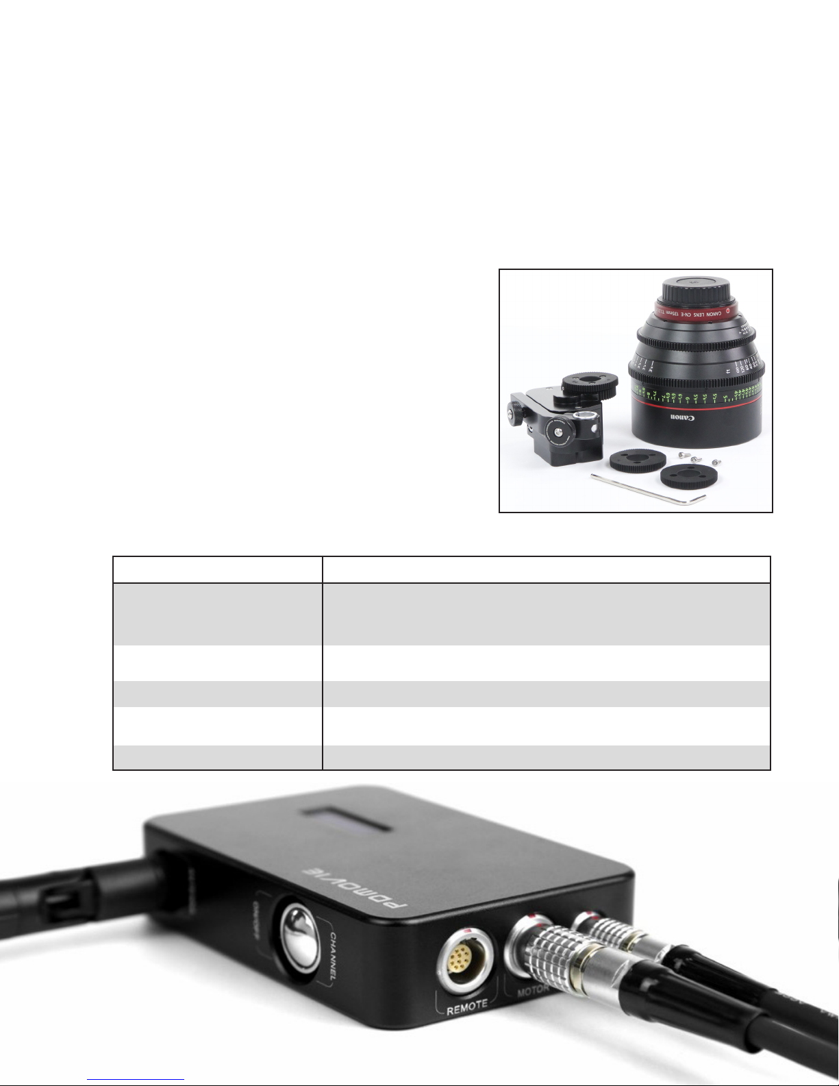
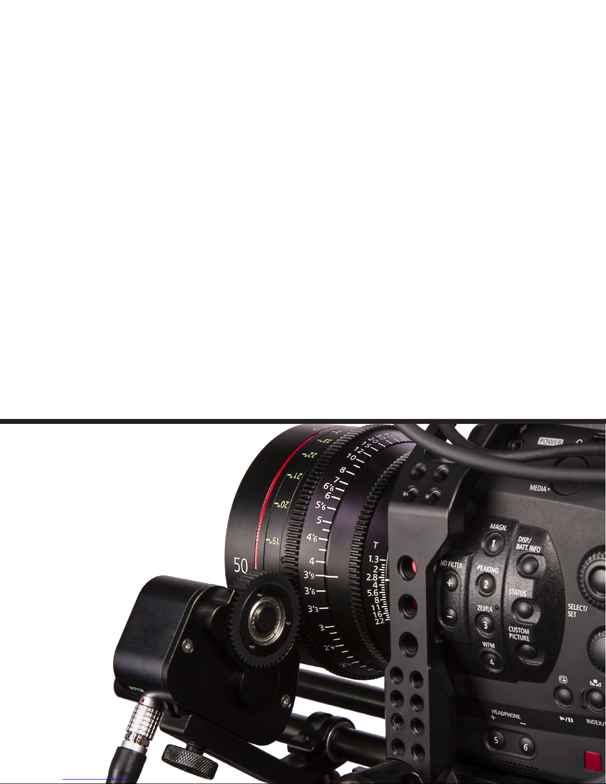
The PD1 and PD2 motors are equipped with a .8
gear. The kits for both PD1 and PD2 are able to adapt
to multiple gears which are available as an optional
accessory. Three additional gears are included with the
PD-GEAR-KIT (.4, .5, and .6) and three hex screws,
which can be installed onto the existing .8 gear (see
picture at right).
Receiver Buttons & Operation
BUTTON / CONNECTION
ON / OFF CHANNEL
ANTENNA
MOTOR
REMOTE
12-20V
Hold for 2 seconds until display shows up.
Quick Press to change channel
INSTRUCTION/FUNCTION
Antenna Connection
Motor Connector
Optional Wired Controller
12–20V D-TAP Power Cable
Page 5
Transmitter Button Controls & Operation
BUTTON / CONNECTION
ON / OFF CHANNEL
Focus Nerve
Zoom Nerve
(2 Channel)
Iris Nerve
(3 Channel)
FUNCTION
ON/OFF
CHANGE CHANNEL
Automatic
Scan
Change
Motor
Direction
INSTRUCTIONS
Hold the On/Off button for two seconds, until display powers up.
Select a channel on both receiver and transmitter, and observe
the signal strength. When signal strength reaches 100% you may
begin automatic scan of lens.
You may cycle through 1–20 channels with a quick press of the
Channel Button to find the cleanest signal.
To start Automatic Scan of lens, press and hold for three seconds
until motor begins to turn, then release. The motor will travel one
direction to detect a hard stop and then change direction to find
the other end of the lens or hard stop. Once it finds the primary
lens, calibration is complete.
You may begin to mark your disk with desired lens information.
Note: The Control wheel has a range of digital positions (approx
-0.5 to 500) that correspond to the motor. They are displayed in
the fourth line of the transmitter’s display and may be used as an
additional reference for mapping and re-mapping the lens. This is
helpful when changing lenses. You may use this reference number
for quick stops or to match a previously marked disk/lens.
Quick-press the Nerve button five times to change direction of
motor to match the side of camera from which you choose to
operate, or to change motor rotation if using Nikon or Leica lens
(where rotation is reversed).
Nerve
Set Manual
A-B Stop
Record Last
Manual Setting
After Automatic Scan is completed, you may wish to use a
specific range on the lens for more specific zoom or focus moves.
You can map the whole control surface of the wheel from points
A to B. Setting your A-B Stop is a combination of a button press
and rotation of the controller wheel.
To begin, set the lens in between the two positions you are
choosing. While turning the wheel toward your first stop, press
Set
Cancel
Restart Remote control, then apply one short press of Nerve Button.
Nerve once and release. Then simultaneously press and hold
Nerve again while continuing to your first position. Change
directions and move to your second position; release the Nerve
button when you have reached your other stop. The motor will
reset in the middle of the range you have just mapped. Your A-B
stops will be mapped to the whole range of the focus wheel.
Brief Tutorial: http://vimeo.com/97558755
To cancel your A-B stop and return to Primary Lens Calibration,
double-press the Nerve button. The motor will return to the
middle of the lens position.
3D Mode
To set 3D Mode, Press Nerve Button ten times.
Page 6
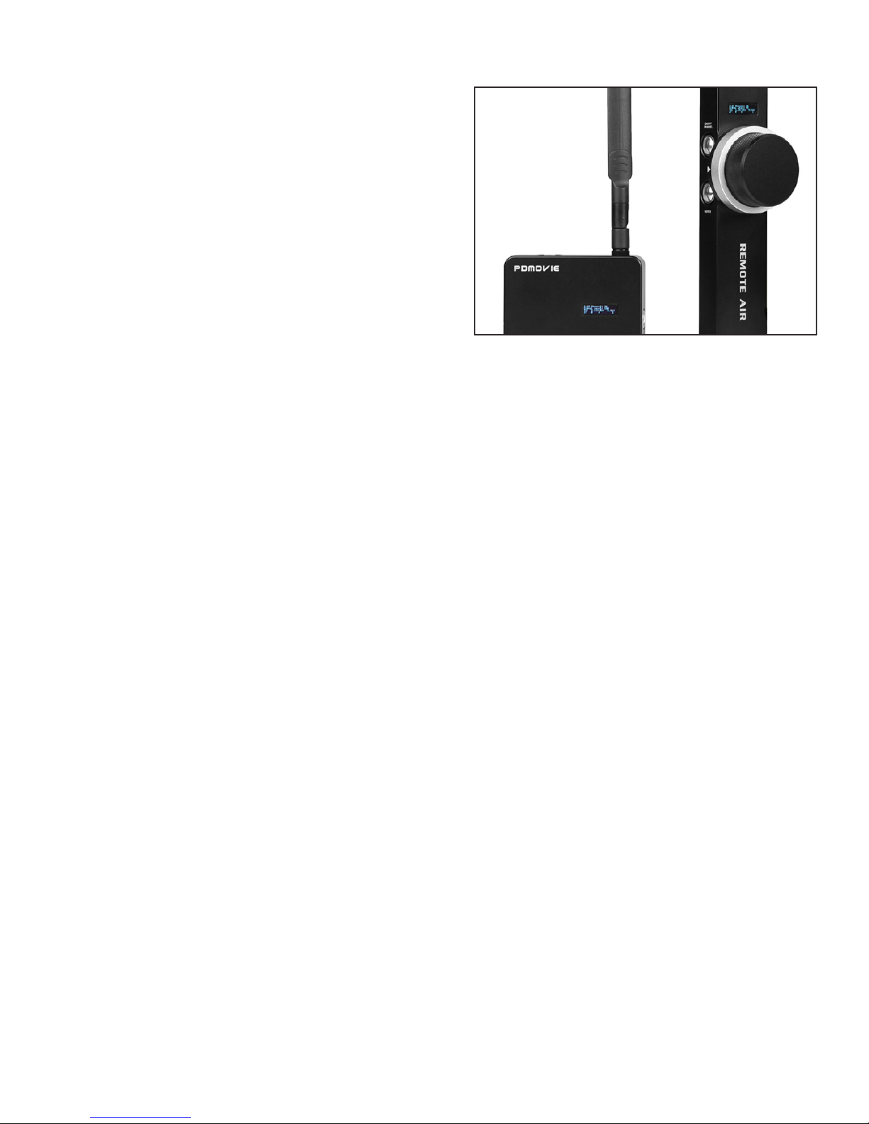
LCD Display Info
Line 1:
Frequency = 2.4 GHz Channel = 1-20 Channels
Line 2:
Signal Level = Signal Connection. If no response,
restart receiver.
Display on Transmitter & Receiver
Line 3:
TX (Transmitter) = Battery level volts. Normal Operating Range.
RX (Receiver) = Battery level volts. Normal Operating Range.
Note: Normal operating range is 3.4 – 4.2v.
If level drops below 3.4v, then the battery needs to be charged.
Line 4:
Displays digital numerical assignments of the control wheel(s): approximately -0.5 – 515.
Note: Four separate numbers are displayed on Line 4. However, the last two are reserved
for future options and software testing.
Tips:
1. Check that the correct cables are being used before operation.
2. During normal operation the motor will heat up; this is normal.
3. The motor is designed for cold weather, but will not work at
temperatures under -20˚C.
4. The colder the temperature, the more noise the motor will make.
5. When charging the remote, it will automatically restart. When charge is
complete, remove the cable and it will automatically shut down.
6. High temperature may cause oil to form at movable mechanical joints;
this is normal. You may use cleaning cloths to keep these areas clean.
7. If unit fails to scan, check Lemo connections and reattach.
8. After power-up, if there is no signal pairing to the receiver, change
channels and repeat power-up until signal appears.
Note: Always power on the Transmitter FIRST, then the receiver when pairing
the device.
Page 7
Optional Accessories Exclusive to PD Movie
PDL
PD Movie Remote Live
PD1
PD Movie Remote Air 1
PD1-HT
PD Movie Remote Air High Torque
BA1
BlackMagic Armor System Kit
PD-CBL
PD Movie Motor Drive Cable
PD-6FTCBL
PD Movie Extended Motor Drive
Cable
PD-12FTCBL
PD Movie Extended Motor Drive
Cable
PD-GEAR-KIT
PD Movie Motor Drive Gear Kit
PD-HTMTR
PD Movie High Torque Motor
Assembly
PD-MTR
PD Movie Standard Drive Motor
Assembly
PD-PD1RX
PD Movie PD1 Receiver
PD-PD2RX
PD Movie PD2 Receiver
PD-PD1TX
PD Movie PD1 Transmitter
PD-PD2TX
PD Movie PD2 Transmitter
PD GEAR
PD Movie Main Drive Gear
PD-DTAP
PD Movie D-Tap Power Cord
PD-DC-PWR
PD Movie DC Power Cord
PD-DISK
PD Movie Marking Disk
PD-ANT
PD Movie Antenna
PD-SHRT-ANT
PD Movie Short Antenna
PD-CHRG
PD Movie USB Power Adapter
PD-RNG
PD Movie 15mm-19mm Step Down
Ring
PD-DISK-GLO
PD Movie Glowing Marking Disk
PD-USBCBL
PD Movie USB Charging Cable
PD-STRAP
PD Movie Replacement Strap
PD-HEX
PD Movie Hex Bolt
Page 8

Learn More
More dynamic information at official website: www.ikancorp.com
Support
Contact email: [email protected]
CONDITIONS OF WARRANTY SERVICE
• Free service for one year from the day of purchase if the problem is caused by manufacturing errors.
• The components and maintenance service fee will be charged if the warranty period is expired.
Free Service will not be Provided in the Following Situations:(*Even if the product is still within the warranty period.)
• Damage caused by abuse or misuse, dismantling, or changes to the product not made by the company.
• Damage caused by natural disaster, abnormal voltage, and environmental factors, etc.
©2015 ikan Coporation. All rights reserved
 Loading...