

Page 1
Reference : K0J00002
Indice : 02A04
Date : 2018-02-23
Page : 1/15
Autonomous Wireless Overflow Detector
Product code: LSC
Tutorial
CONFIDENTIALITY
All information in the following document are strictly confidential.
Further use of this document and its content must be submitted and approved by IJINUS.
This device complies with FCC radiation exposure limits set forth
for general population. This device must not be co-located or
operating in conjunction with any other antenna or transmitter.
Page 2

Reference : K0J00002
Indice : 02A04
Date : 2018-02-23
Page : 2/15
Document updates
Ref Date Modification
01A01 2011*09/09 Initial draft
02A01
2014/11/15
Translation
02A04
2018/02/13
FCC warnings updated
Page 3

Reference : K0J00002
Indice : 02A04
Date : 2018-02-23
Page : 3/15
Summary
Introduction........................................................................................................................................................................4
2. Principal of Operation..................................................................................................................................................... 6
............................................................................................................................................................................................ 6
3. Autonomous overflow detector...................................................................................................................................... 7
3.1 Specifitities.................................................................................................................................................................... 7
- Radio frequencies:......................................................................................................................................................... 7
- Measurements: Time outs and detection thresholds.......................................................................................................7
- Data recovery: Remotely via GSM/GPRS data logger or on site........................................................................................7
- Overflow alarms: Beginning and end of an overflowing event.........................................................................................7
3.2. Set-Up with the AVELOUR Software.............................................................................................................................8
3.3. Battery life guideline..................................................................................................................................................12
4. Field testing results....................................................................................................................................................... 12
5. Maintenance................................................................................................................................................................. 13
The Autonomous Overflow Detector is designed to operate in rough and dirty environments. We recommend a
periodic cleaning cycle to optimize use and accuracy.......................................................................................................13
6. Case technical specificities............................................................................................................................................14
7. Warning to users in the United States........................................................................................................................... 15
Page 4
Detection Area
Reference : K0J00002
Indice : 02A04
Date : 2018-02-23
Page : 4/15
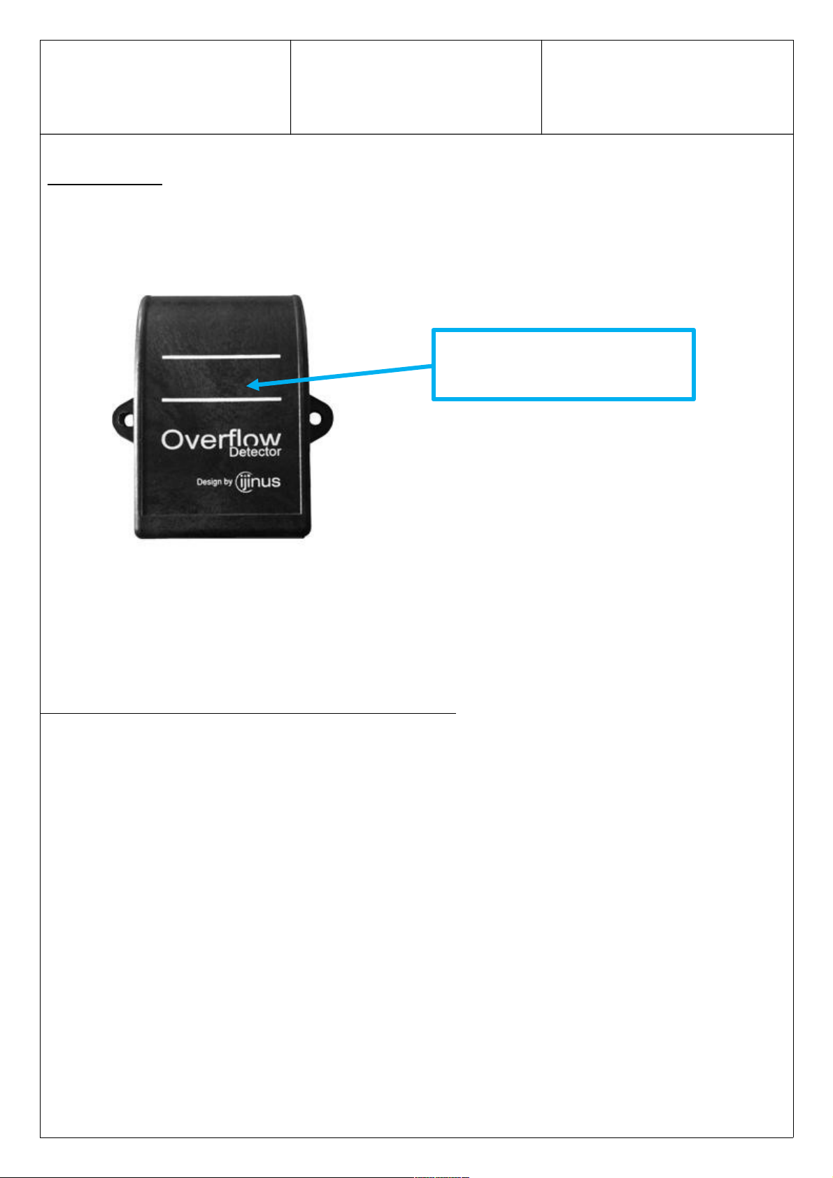
Introduction
The Autonomous Overflow Detector will detect the presence of water (or any conductive fluid) above
a threshold (ON/OFF state). The detection area is clearly marked on the case by 2 white lines which
allows a precise installation. The user will simply position the detection area at the threshold level
required.
A capacitive measure will detect water on the case surface. Note that the measuring system is
located inside the case.
In order to improve their accuracy, the capacitive measurements are temperature compensated.
1. Presentation of the Capacitive Technology
The measuring system works around an electrode fixed on the inside of the case, directly behind the
detection area. An electric field is triggered from the electrode and travels towards the outside of the
case. The electrode and the outside environment (water) on the detection area will then become the
2 terminals of the passive capacitor which will create an electric capacity. This capacity will vary
depending on the dielectric constant of the environment and its electrical conductivity.
Based on this principal, the higher the environment’s dielectric constant, the higher the capacity
measure will be. As an example, the dielectric constant of dry air equals 1, while water’s equals 80.
Page 5

Reference : K0J00002
Indice : 02A04
Date : 2018-02-23
Page : 5/15
Advantages and comparison against mechanical and resistive systems
The advantage of the capacitive technology is the fact that there is no direct contact between the
detection system and the environment (which is not the case of conductive systems). Mechanical
systems (floaters), are often failing due to clogging, impacts or foreign objects.
Conductive Mechanical Capacitive
Page 6

Reference : K0J00002
Indice : 02A04
Date : 2018-02-23
Page : 6/15
2. Principal of Operation
The abscissa represents the presence of water in percentage. The ordinate indicates a timeline in
seconds.
The capacitive measurement cycle of the sensor is 5 seconds. The black curve indicates the
presence of water (= capacitive value) at each cycle of measure. The red curve indicate the
averaged capacitive value which applies a timed out factor to the detection measured. Based on the
type of overflowing events that the user wishes to monitor (with our without taking in consideration
short events such as waves), the set-up of this time out factor will vary. If the user wished to monitor
short events, the time out time in seconds shall be short (close to 0s). In the contrary if the user only
wishes to monitor long lasting overflowing events, the time out time (in seconds), shall be longer
(over 30s).
Activation and de-activation of the overflow detection is based on the averaged capacitive value.
The detection is activated (ON) when the average capacitive value reached the detection threshold
level. The detection is de-activated (OFF) when the above mentioned value decreases below the
threshold level, to which is deducted a dielectric hysteresis.
If the user wishes to monitor moist depot, a low threshold shall be selected and vice-versa.
Averaged Capacitive Value
Capacitive Value
Overflow OFF
Overflow ON
Time out lapse
Detection Threshold in %
Page 7

Reference : K0J00002
Indice : 02A04
Date : 2018-02-23
Page : 7/15
Refer to part 3.2 for further details.
3. Autonomous overflow detector
3.1 Specifitities
- Radio frequencies:
- Measurements: Time outs and detection thresholds.
- Data recovery: Remotely via GSM/GPRS data logger or on site.
- Overflow alarms: Beginning and end of an overflowing event.
Warning:
The Autonomous Wireless Detector features an “earth patch”. This patch must be submerged
while an overflowing event occurs. The user must install the detector in the following positions:
Page 8

Reference : K0J00002
Indice : 02A04
Date : 2018-02-23
Page : 8/15
3.2. Set-Up with the AVELOUR Software
- Open AVELOUR Software
- Click on “Connect to a Device”
- Select a Wireless Overflow Detector (IJM-6012xxxx)
- On the main screen, click on “Advanced Parameters”
« Overflow Counter » tab :
- Select if the user wishes to record overflowing events or not.
- Select the time out lapse: Select the number of seconds after which the overflowing event
shall start to be recorded (default = 30s).
- Select the Detection Threshold level:
o Low (moist deposit) = 20%
o Average (clogging) = 50%
o High (body of water) = 80% (Default)
o Very High = >80%
- Select a Recording Type = Fixed or Rotating (FIFO) [In Expert Mode].
Page 9

Reference : K0J00002
Indice : 02A04
Date : 2018-02-23
Page : 9/15
« Alarms » tab :
- Select if the user wishes to trigger alarms at the beginning and/or at the end of an
overflowing event.
- Select the time out lapse (minimum time) in seconds after which the alarm shall be
triggered. Note that the alarm will only be sent if the overflowing even remains constant
during the selected minimum time.
Alarm sending parameters [In Expert Mode]:
- Attempts: In case of a difficult environment between the Detector and the Data Logger,
this option allows the user to enable multiple attempts to send the alarm signal. This
option automatically stops once the alarm has been successfully received by the Data
Logger.
- Minimum time between alarms: This option allows the user to select a minimum time in
seconds between 2 alarms in order to optimize the alarm sending cycle.
« Alarms » tab [In Expert Mode]:
This tab will allow the user to change the size of the main and auxiliary files sent by the Detector.
Page 10

Reference : K0J00002
Indice : 02A04
Date : 2018-02-23
Page : 10/15
Note that auxiliary files are used to send data to the Data Logger and are deleted after each data
transfer.
NB:
1. To access the Device properties and status: click on File > Device Properties and then click on
Refresh. The Icon at the top right corner of the main screen will also indicate the device’s status
(completely covered in blue = Overflowing event is ON, half covered in blue = event is OFF).
Page 11

Reference : K0J00002
Indice : 02A04
Date : 2018-02-23
Page : 11/15
2. Retrieving measures and graph display of overflowing events:
Click on Actions > Retrieve measures. The grey bars show the overflowing events.
Page 12

Reference : K0J00002
Indice : 02A04
Date : 2018-02-23
Page : 12/15
3.3. Battery life guideline
Capacitive measure cycle Data retrieving cycle Battery life
10 sec 12 h 6,52 years
5 sec 12 h 4,91 years
1 sec 12 h 1,66 year
Important / Battery change:
It is paramount that you contact us once the detector’s battery reaches the end of its life. IJINUS
and IJINUS only will replace the battery and will be able to deliver a sound and certified detector
back to the user.
4. Field testing results
Water eight (in mm)
Capacitive measures
Overflow (ON/OFF)
Page 13

Reference : K0J00002
Indice : 02A04
Date : 2018-02-23
Page : 13/15
For each site, the 3 graphs represent:
- The water eight (in mm) measured by an IJINUS Ultrasonic Level Sensor. The horizontal
line shows the overflow threshold level.
- The Capacitive detection of water in percentage.
- The Detector status (ON/OFF).
5. Maintenance
The Autonomous Overflow Detector is designed to operate in rough and dirty environments. We
recommend a periodic cleaning cycle to optimize use and accuracy.
Refer to the below in case of anomalies
- Absence or incoherence of measures:
Water Eight (in mm)
Capacitive measures
Overflow (ON/OFF)
Page 14

Reference : K0J00002
Indice : 02A04
Date : 2018-02-23
Page : 14/15
Possible causes Examples Corrective actions
Clogging Clogging is too important and
disturbs the capacitive
measurements.
Clean the case’s surface with a humid
cloth.
Water proofing
issues
The case was damaged by water. Return the product to IJINUS.
Damaged case A foreign object has violently
collided with the detector.
The product cannot be used if the
detection area is damaged of if it is no
longer water proof.
Return the product to IJINUS.
Battery issues The battery has reached the end
of its life.
Return the product to IJINUS for
battery replacement
Safety and recommendations
Do not open the product’s case
Only use suitable screws on installation (max 6mm diameter).
Use within the recommended temperature spectrum
Do not clean with an abrasive product/detergent
The case must not be modified by the user
Stock the product between 5°C and 25°C
Install the product on a flat surface
6. Case technical specificities
IP68
High resistance to corrosion
High resistance to chemical products
Page 15

Reference : K0J00002
Indice : 02A04
Date : 2018-02-23
Page : 15/15
7. Warning to users in the United States
Caution: the user that changes or modifications not expressly approved by the party
responsible for compliance could void the user's authority to operate the equipment.
"NOTE: This equipment has been tested and found to comply with the limits for a Class B
digital device, pursuant to part 15 of the FCC Rules. These limits are designed to provide
reasonable protection against harmful interference in a residential installation. This
equipment generates, uses and can radiate radio frequency energy and, if not installed and
used in accordance with the instruction, may cause harmful interference to radio
communications. However, there is no guarantee that interference will not occur in a
particular installation. If this equipment does cause harmful interference to radio or
television reception which can be determined by turning the equipment off and on, the user
is encouraged to try to correct interference by one or more of the following measures:
- Reorient or relocate the receiving antenna.
- Increase the separation between the equipment and receiver.
- Connect the equipment into an outlet on circuit different from that to which the receiver
is connected.
- Consult the dealer or an experienced radio/TV technician for help.
This device complies with FCC RF radiation exposure limits set forth for general population.
This device must be installed to provide a separation distance of at least 20cm from all
persons and must not be co-located or operating in conjunction with any other antenna or
transmitter.
 Loading...