

iiNet ADSL2+ Modem, F1PI242EGau User Manual
Broadband Voice Modem/Router
ADSL2+ Modem User Manual

Introduction
1
2
1
3
4
5
6
7
sec tion
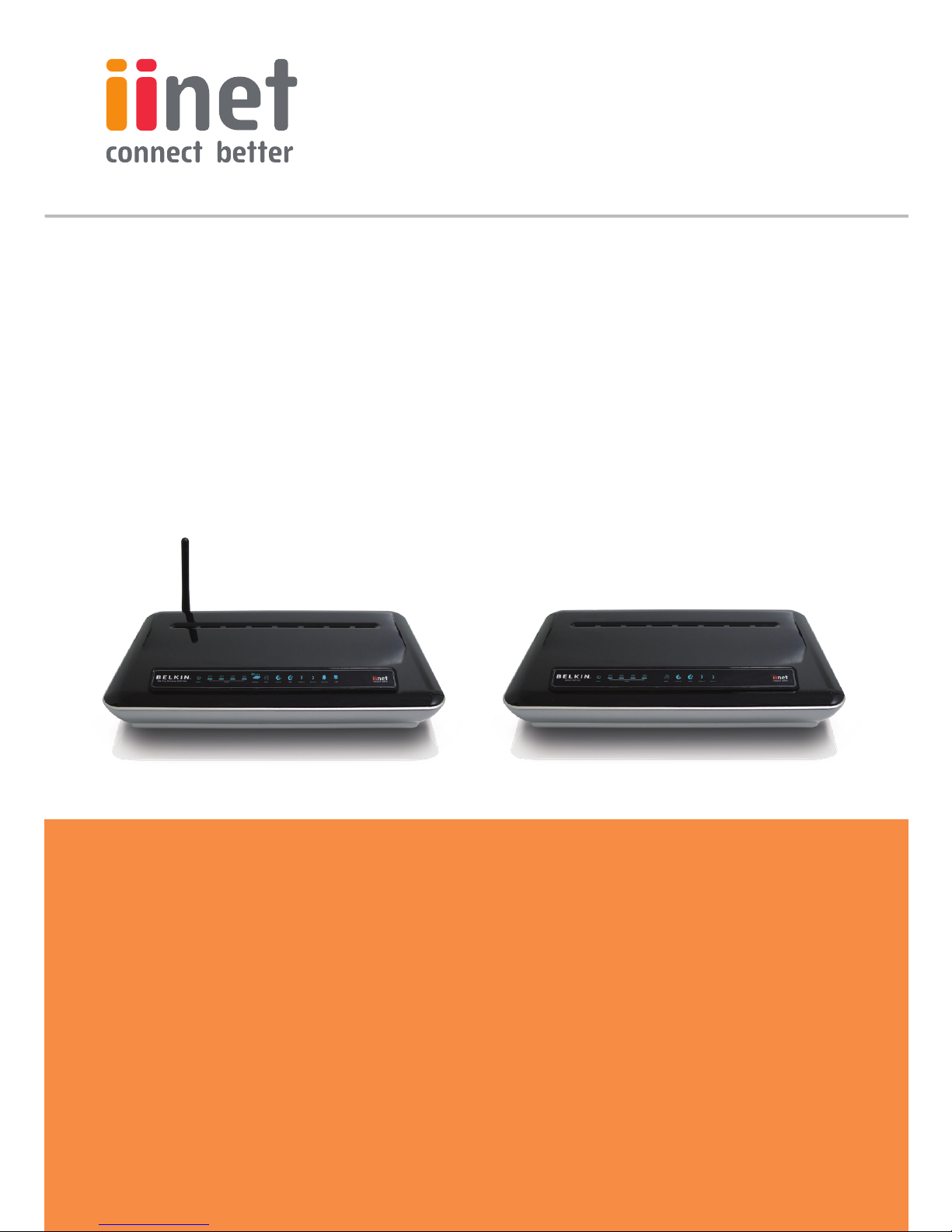
Tha nk you fo r p urchasi ng the Be lkin ADSL2+ Mode m. This m anual
app lies to b oth the 4 Po rt Wired (F1PI24 2ENau) and the 4 Port
Wireless (F1P I242EGa u) VoIP AD SL2+ Modem Route rs. In minutes you
wil l be able to conne ct to the In ter net and m ake Voice over Inter net
Pho ne calls. The 4 Po rt Wireles s ( F1PI242EGa u) unit also offers tw o
sec ure networ k and the ot her a pub lic Ho tspot network. T he following
is a list of features that make your Modem an ideal solution for your
hom e or smal l o ffice and will con tain i mportan t info rmation on how to
get what you wa nt out of your VoIP Ro uter s o p lease read carefully
bef ore settin g up your router.
Introduction
1
1. Introduction . . . . . . . . . . . . . . . . . . . . . . . . . . . . . . . . . . . . . . 1
2. Product Overview . . . . . . . . . . . . . . . . . . . . . . . . . . . . . . . . . . 2
3. Knowing your VoIP Router . . . . . . . . . . . . . . . . . . . . . . . . . . . 6
4. Connecting and Configuring your Router . . . . . . . . . . . . . . . 10
5. Advan ced Setup Method . . . . . . . . . . . . . . . . . . . . . . . . . . . 15
6. Appendices . . . . . . . . . . . . . . . . . . . . . . . . . . . . . . . . . . . . . 88
7. Glossary . . . . . . . . . . . . . . . . . . . . . . . . . . . . . . . . . . . . . . 100
Table of Contents

32
Product Overview
Product Overview
3
2
1
3
4
5
6
7
sec tion
Bui lt- in Dyn amic H ost Co nfi guratio n Prot ocol ( DHCP)
Bui lt- In Dyn amic H ost Co nfiguratio n Protocol (DHCP) on-board make s
for the easiest possible conne ction of a network . The DHCP server
wil l assi gn IP addresses t o e ach co mpu ter au tomaticall y so there is
no need for a c omplicated networki ng set up.
DMZ Host Suppo rt
DMZ Host Suppo rt all ows a networked compu ter to be fully exposed
to the Internet. This function is used w hen NAT and fire wall s ecurity
prevent an I nterne t appl ication from functi oning correctly.
NAT IP Add ress Sharing
Your Modem employ s Netw ork Ad dress Translation (NAT) to s hare the
sin gle IP address ass igned to you by your Internet Service Prov ider
whi le sav ing th e cost of adding additional IP addre sses t o your
Int ernet servic e acco unt.
SPI Firew all
Your Modem is equipped with a f irewall that will prot ect yo ur net work
from a wide array of common hacker attac ks inc lud ing:
IP Spoof ing , L and At tac k, Pin g of Death (PoD), Denial of Service
(Do S), IP with zero len gth , S mur f A tta ck, TC P Null Scan, SYN flood,
UDP flood ing , Tear Drop Att ack, I CMP de fect, RIP de fect, and
fra gme nt flo oding.
Uni ver sal Pl ug-and-Pla y (UPn P) Com pat ibility
UPn P (Uni ver sal Pl ug-and-Pla y) is a technolog y that offers s eam less
ope rat ion of vo ice messa ging, video messaging, games, and other
app lic ations that are UPnP-comp liant.
Bel kin Br oadband Voice Modem /Ro ute r - 4 Port
Par t # F 1PI242E Nau (Wired)
Com pat ibility with bo th PC’s and
Mac® C omputer s
The Modem suppo rts a variety of
net wor king e nvironm ents i ncluding
Mac OS® 8.x, 9.x & v10.x , Appl eTalk®, Linux®, Windows® 98SE, ME, NT,
200 0 and XP and others. You need an Int ernet bro wser a nd a network
ada pte r t hat su ppo rts TC P/IP ( the st andard langu age of the Internet).
Int ernet Access
This device supports Internet acc ess through an ADSL co nnection.
Since many ADSL providers use PPPoE or PPPoA to establish
communications with end users, the VoIP Router in clud es built-in clients
for these protocols, eliminatin g the need to install these services on
you r comp ute r.
Fro nt-Panel LED Display
Lig ht LED ’s o n the fro nt of the Modem indicate which funct ions a re in
ope rat ion. You’ll know at-a-glanc e whether your Modem is connected
to the Internet. This feature elimi nates the ne ed for advan ced so ftware
and statu s-m onitoring procedure s.
Web- Bas ed Adv anced User I nterface
You can set up t he Mod em adv anc ed fun ctions easily throu gh you r
web browser, with out ha ving t o inst all ad ditional software onto the
com put er. There a re no dis ks to instal l or keep track of a nd, be st of all,
you can make changes and perform setup functions from any compu ter
on the network quick ly and easily.
54
Product Overview
Product Overview
5
2
1
3
4
5
6
7
sec tion
Bel kin Br oadband Voice Modem with Wirele ss Rou ter - 4 Port
Par t # F 1PI242E Gau (Wireless)
Has all the features above but also has:
Wir ed & Wire less L AN
The VoIP Router p rovides access
for up to 4 by 1 0/100 Mbps wi red
dev ice s and up t o an addition al 32
wireless devi ces, makin g i t easy to
create a netw ork in sma ll offices or homes.
Tomiz one Ho tsp ot
A p ubl ic hotspot is a feature that y ou can enable to share your
broadband con nection se curely and make mone y. When ena bled, this
add iti onal Wireless Sig nal is availa ble for devic es to connect to the
Int ernet. Users eit her pay or ge t free acc ess away f rom your i nternal
net wor k with all billing done by Tomizone .
MAC Addre ss Fil tering
For ad ded securi ty, you can set up a list of MA C a ddresse s (unique
cli ent identifie rs) that are allowed access to yo ur network.
Eve ry computer h as its own MA C addre ss. Simply en ter these MAC
add resses int o a list u sin g the web- based user in terface and y ou can
con trol acces s to your net work.
WEP, W PA a nd WPA 2 Encr ypt ion protoc ols
The Ro uter featu res WPA2, which is the secon d generation of the
WPA-based 8 02. 11i standa rd. It offers a h igher leve l o f wirel ess
sec uri ty by comb ining advance d network aut henticatio n and
stronger Adva nced Encry pti on Standard (AES) en cryption m eth ods.
It als o supports the legacy s ecurity st and ard cal led Wired Equivalent
Pri vac y (WEP) in order to allow y ou to acti vate security with any legacy
dev ice s you may have in your network.
VLA N
VLA N ( Virtual Local Area Network) adds the abi lity to ma nag e multiple
net wor ks with th e one modem.
Product Overview
QoS
QoS (Qual ity of Service) limit s the traffic b eing s ent from the mo dem
(up stream) when using VoIP at t he sam e time . If Qo S is disable d,
the quali ty of the VoIP call can su ffer due to exc essive traffi c from
ano the r s ource, such as a PC. When Q oS is enable d, it limit s the
ups tream traffic an d sets it aside for VoIP, incre asing the ca ll qua lit y.
Vir tual S erver
If you have a fixed IP addres s, you can set the VoIP Router to ac t a s
a virtual host for network ad dres s t ranslation. Re mote users access
various services at you r s ite using a constant IP ad dres s. Then,
depending on the requested ser vice (or port number ), the VoIP Ro uter
can route the request to the appropri ate server (at another internal IP
address). This se cure s y our network from direct attack by hac kers, and
provides more flexibl e m anageme nt by allowing you to chan ge interna l
IP addresses without aff ecting outside access to your net work.
Sup por t f or VPN Pass-Through
If you connect to your office netwo rk from h ome us ing a VPN
con nec tion, your M odem w ill al low yo ur VPN -equipped computer to
pas s through the M ode m a nd to your office n etwork.
Thi s VoIP Router suppo rts th ree of th e most commo nly us ed VPN
protocols – PPTP, L2TP, a nd IPS ec. Th e VPN pro tocols supported by
the VoIP Router are brie fly de scribed below.
• Po int-to-Poi nt Tunnelin g Protocol – Provides a secure tunne l for
re mot e clie nt acc ess to a PPTP security gateway. PP TP inc ludes
provi sions for ca ll ori gination and flow control re quired by ISPs.
• L2 TP merges the best features of PPTP and L2F – Lik e PPTP, L 2TP
re qui res that the IS P’s rout ers su pport the protocol.
IP Secur ity – Provides IP ne two rk-layer encrypt ion. I PSec c an sup por t
large encryption netwo rks (s uch as the Internet) by us ing di gital
cer tif icates for d evice authentica tio n.

76
Knowing Your VoIP Router
Knowing Your VoIP Router
7
sec tion
2
1
3
4
5
6
7
3. WLAN Statu s LED (F1PI 242 EGau o nly)
The WLAN status LED shows you when VoIP Router’s wireless is enabled.
On - W ireless enabled
On - Flashing, a wirele ss con nec tion h as bee n made and data is
tr ans mitting/receiving
Off – Wireless is dis abled
4. ADSL SYNC LED
The AD SL LED fla shes light du ring negot iat ion with y our ISP. It stays
lig ht when the M odem is conne cted properly to you r ADSL servic e.
Off - No ADSL connection
On - Blinking negot iat ing co nnection/N o ADSL sync
On - ADSL link i s up and connected
5. Inter net LED
The In ter net LED sh ows you when the Modem is connected to the
Int ernet. When the L ED is OFF, the M odem is NO T c onnected t o the
Int ernet. When the LED is solid light, the Mo dem is connec ted to the
Int ernet. When the LED is blinki ng, the Modem is transmitt ing or
receiving dat a from the Internet.
Off - Not connecte d to Internet
On – blinking, conne cte d and transm itting or receiving data
On - Connected to Internet
6. VOIP Statu s LED
Whe n y our ADSL c onnection is being used to make VoIP calls from
one of the hands ets connected this ligh t w ill be on to assist you in
kno win g what kin d of traff ic your ne twork working under.
On - VoIP a ctivity
Off - No VoIP activity
7. Phone Statu s LED 1-2
Whe nev er you mak e a phone cal l on one o f t he handset s attached to
the VoIP ro ute r the ligh ts will infor m you of t he current status of th at
The Mo dem is des igned to be p laced on a de sktop. All of the cable s
exi t f rom the rear o f the Modem f or better organis ation and uti lity. Th e
LED in dictors are easil y v isible on the fro nt of the Mod em to prov ide
you wi th informa tion about ne twork acti vit y and stat us.
F1P I242ENau
F1P I242EGau
Fro nt Pan el
1. Power LED
Whe n y ou apply p ower to the M odem or restart it, a short perio d of
tim e e lapses whi le the Modem boots up. Whe n the Mode m has
com ple tely boote d up, the Pow er LED bec ome s a SOLID light,
ind ica ting the M odem is re ady for us e.
Off - Modem is off
Ora nge - Modem is booting
Blu e - Modem is o n and rea dy for use
2. LAN Status LED 1-4
Whe n a computer is prop erl y connecte d to the LAN port on the rear of
the mo dem, the a ssociated LED will ligh t. A solid li ght means a
com put er or a ne twork-enabled device is co nnected. W hen
inf orm ation is b eing sent ove r the port , t he LED bli nks rapidly.
Off - Your compu ter is not connected
On - Flashing, compu ter conne cted a nd tra nsmitting or recei ving d ata
On - Your computer is connected
1 2 4 5
8
3 6
7
9
1 2 4 5 6
7
98
Knowing your VoIP Router
Knowing your VoIP Router
9
sec tion
2
1
3
4
5
6
7
pho ne call.
On - VoIP a ctivity, i. e. pho ne is in use
On - Flashing, Incom ing call, i.e., phone is ringing
Off - No VoIP activity
8. Tomi zon e ( F1P I242EGa u only )
Thi s l ight will illuminate wh en Tomizone is enabled an d activate d.
On – Tomizone enabled and activate d
Off – Tomiz one di sab led/deacti vated
9. USB (F1PI24 2EG au onl y)
Whe n a USB mass storage devic e is conne cte d to the U SB Port, this
lig ht will illum inate to info rm you the at tached sto rage device i s ready
for us e.
On – Attached USB Mass Storag e D evice connecte d a nd read y f or use
Off – No attach ed USB Mass Storag e Devi ce
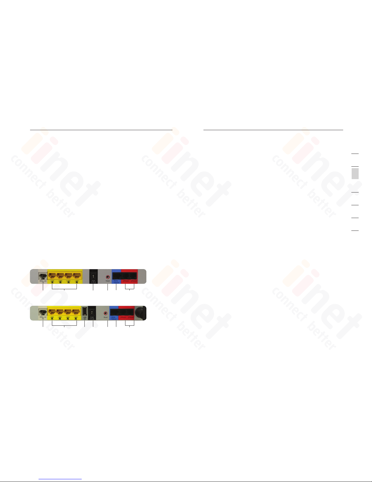
F1P I24 2ENau
F1P I24 2EGau
Bac k Pane l
1. ADSL Line
Thi s p ort is for connection t o your ADS L l ine. Conne ct your ADSL line
to thi s port.
2. LAN Ports
The Et her net port i s R J45, 10/10 0 auto-negoti ation. Connec t your net
wor k-e nabled com puters or any networkin g d evices to this port.
3. USB (F1PI24 2EG au onl y)
USB po rt for att aching USB Ma ss Storage De vices.
4. Power Plug
Con nec t the incl uded 12V 1A D C power su ppl y to this inlet. Using the
wrong type of power ada pte r may caus e damage to y our Modem.
5. Reset Butto n
The “R eset” butt on is used in rare c ases when the Modem may
fun cti on improperly. Resetting th e Modem wi ll rest ore the Mo dem’s
nor mal operation while mainta ining the programmed settings. You can
als o restore the fac tory default settings b y u sing the R ese t button. Use
the restore option i n instances w here yo u may have fo rgotten your
cus tom password.
a. Reset tin g t he Mod em
Pu sh and hol d the Reset b utton for one second th en release it.
Wh en the PWR light become s solid ag ain the re set is comple te.
b. Resto rin g t he Fac tor y Defa ult s
Pu sh and hol d the Reset b utton for ten seconds t hen releas e it.
Wh en the PWR light become s solid ag ain the re store i s c omplete.
6. PSTN Failo ver Po rt
The Op tional RJ- 11 port is fo r connecti on to your PS TN (Home Phon e)
lin e t o provi de Normal Pho ne call ba ckup for when VOIP is unav ailable
or not required.
7. Phone Port
Phone Ports connect to standard analogue telephone set or fax machine.
1 2 4 5
6 7
1 2 4 5
6 7
3

1110
Connecting and Configuring your Router
Connecting and Configuring your Router
11
sec tion
2
1
3
4
5
6
7
con nec t y our PC or other network equipment to the hub or sw itc h.
Whe n inse rti ng an RJ-45 connec tor, be sure the tab on the co nnector
cli cks in to pos iti on to ensure th at it is pro per ly sea ted.
War ning: Do not pl ug a phone jack connecto r into an RJ-45 port. This
may damag e the VoIP Router. Instead, use only twisted-pa ir cab les
wit h RJ-4 5 conn ect ors th at con form t o Aust ralian standards .
Not es:
1. Use 100-o hm shi eld ed or unshie lded t wisted-pai r cable with
RJ- 45 con nec tors f or all Ether net ports . Use Categ ory 3, 4, or
5 for connectio ns that operate at 10 Mbps, and Cat egory 5 f or
con nec tions that o perate at 10 0 Mbps .
2. Mak e sure ea ch twi ste d-pair cable length does not e xceed 100
met ers (3 28 fee t).
Ste p 4. Connect the power adapter
Plu g the power adapt er into the power socket on t he rear panel of t he
VoIP Route r, and the other en d i nto a power outle t.
Che ck the power indicato r on the fro nt panel is lit. If the po wer
ind ica tor is no t lit, re fer to “Troubl eshooting” .
In case of a po wer fa ilure, the VoIP Router will automatic ally restart
and begin to operate once the power is restored.
At this time we have now c ompleted connecting the rout er and may
now move to the actual configuratio n of your connecti on.
* Time needed to obtain line sync w ill va ry dep end ing on va rio us
fac tor s s uch as line noise and attempted sync speed.
Ste p 1. Find a su ita ble lo cation
The VoIP Router can be positioned at any convenient location in your
office or ho me whe re there is easy a ccess to a phone jack and power
poi nt nea rby. No sp ecial wiring or co oling requirements are needed
and there is no necessit y to keep the unit c onnected dire ctl y to a
com put er.
You should, howev er, comp ly wit h the follo win g guid elines:
• Keep the VoIP Router away from any heating devices
• Do not pl ace th e Vo IP Rou ter in a dusty or we t envi ronment
You should also reme mber t o turn off the power, remove the power
cord f rom the o utlet, and k eep yo ur han ds dry when you install the
VoIP Route r.
Ste p 2. Connect the ADSL L ine
Pho ne lin e conf igu rat ion
Run stand ard telephone cable from the wall jack providi ng ADS L
ser vic e t o the RJ-11 (“ADS L”) port on your VoIP Router. Wh en
ins ert ing an AD SL RJ-11 plug, be sure the tab on the pl ug cli cks in to
pos iti on to ens ure th at it is properly seated. If you are u sing a split ter
les s ADSL servi ce, be sure you add low-pass filters betwe en the
ADS L wall jack and your telephones. (Thes e filt ers pa ss voi ce sig nals
through but filter da ta sig nals o ut.)
Not e: If more tha n 4 connecti ons of any kind (i.e. faxes, phones,
mod ems et c) are to be used you w ill ne ed to get a ce ntral splitter
ins tal led.
Ste p 3. Attach to y our ne twork using Ethernet cab ling
The LAN ports on the VoI P Rout er aut o-negotiates the connecti on
spe ed to 10 Mbps Ethernet or 10 0 Mbps Fast Ether net, as well a s t he
tra nsm ission mode to hal f dupl ex or full duplex.
Use twist ed- pair c abling to co nnect any of the LAN ports on th e VoIP
Rou ter to an Ethernet a dapter on yo ur PC. Other wise, cascade the
LAN port on the VoIP Ro uter t o an Ethernet hub or sw itch, and th en
1312
Connecting and Configuring your Router
Connecting and Configuring your Router
13
sec tion
2
1
3
4
5
6
7
Mak ing Co nfi guration Changes
Con fig urable parameter s have a dialog box or a drop -down list. Once
a configu rat ion ch ange h as bee n made on a pa ge, mo st of the time
you will need to click the “SAV E S ETT INGS” or “NE XT” bu tton a t the
bot tom of the page to e nable the ne w sett ing . U nle ss the re is a “ADD ”
but ton fo r inst anc e.
Not e: To ensure p roper screen ref resh after a command entry, be sure
tha t Inte rnet Explorer 5 .0 and above is configured as fol lows: Under
the menu Tool s/Internet Options/Gen eral/Tempora ry Int ern et Fil es/
Set tin gs, th e s ett ing fo r “Che ck for newer versi ons of stored p ages”
sho uld be “Ever y visit to the page.”
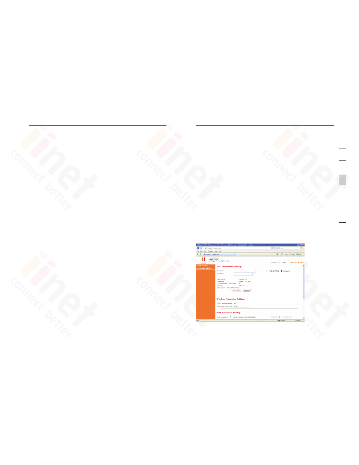
Ste p 3. Using Setup Wizard
Thi s page allow s you to quickly setup basic settings of the mo dem to
get you connect ed quickl y. After making a c hange click on the save
set tin gs but ton on the scre en to app ly the changes.
Ste p 1. How to lo g into the Router
Aft er you have confi gured TCP/IP on a cli ent compu ter, use a web
browser to c onfigure the VoIP ADSL Wirele ss Rou ter. The VoIP Router
can be configured by any Java- sup ported browse r such as Internet
Exp lorer 5.0 or ab ove . U sin g t he web manageme nt int erface, you
may confi gure the VoIP Ro uter a nd vie w stat istics to mo nit or net work
act ivi ty.
To access the VoIP Router’s man agement interface, enter the IP
add ress of t he VoIP Route r in your web browser : 10.1 .1. 1
Not e: If you are unabl e to access this web page please look at t he
IP setup secti on of the Troublesh ooting section at the ba ck of this
man ual .
Type in “admin” as the password and click login. NOTE: Password i s
cas e sens iti ve.
ISP Setti ngs
Ple ase co lle ct the follo wing i nformation from you r ISP before s etting
up the VoIP Router:
• ISP accou nt user name and password
• Protocol, encapsulation and VPI/VCI circuit numbers
• DNS serve r address
• IP address, subnet mask and default gateway (for fixed IP users only)
Ste p 2. Navigat ing the web bro wse r i nte rfa ce
The VoIP Router’s ma nagement interfa ce con sis ts of a Setup Wizard
and an Advanced Setup section.
Set up Wizard: Use th e S etup Wizard to quickly set up the VoIP Route r.
Adv anc ed Set up: Ad vanced Setup supports more adv anced functions
lik e hack er att ack detec tion, IP and MAC address fi ltering, virtual
ser ver se tup , v irt ual DM Z host , as well as o ther f unctions.
Not e: If you would like to a dd any addit ional fun ctions to yo ur VoIP
Rou ter pl eas e v iew the Advance d Setu p tabl e of content s in orde r to
fin d the correct setup met hod.
1514
Connecting and Configuring your Router Advanced Setup Method
15
sec tion
2
1
3
4
5
6
7
VOI P Para met er Set tin g
Use r Name : Ente r your VoIP account user name for you ISP
Pas swo rd: Enter your VoIP account password f or you ISP
ADS L Para met er Set tin g
Use r Name : Ente r your internet account user name for you IS P
Pas swo rd: Enter your internet account password fo r you ISP
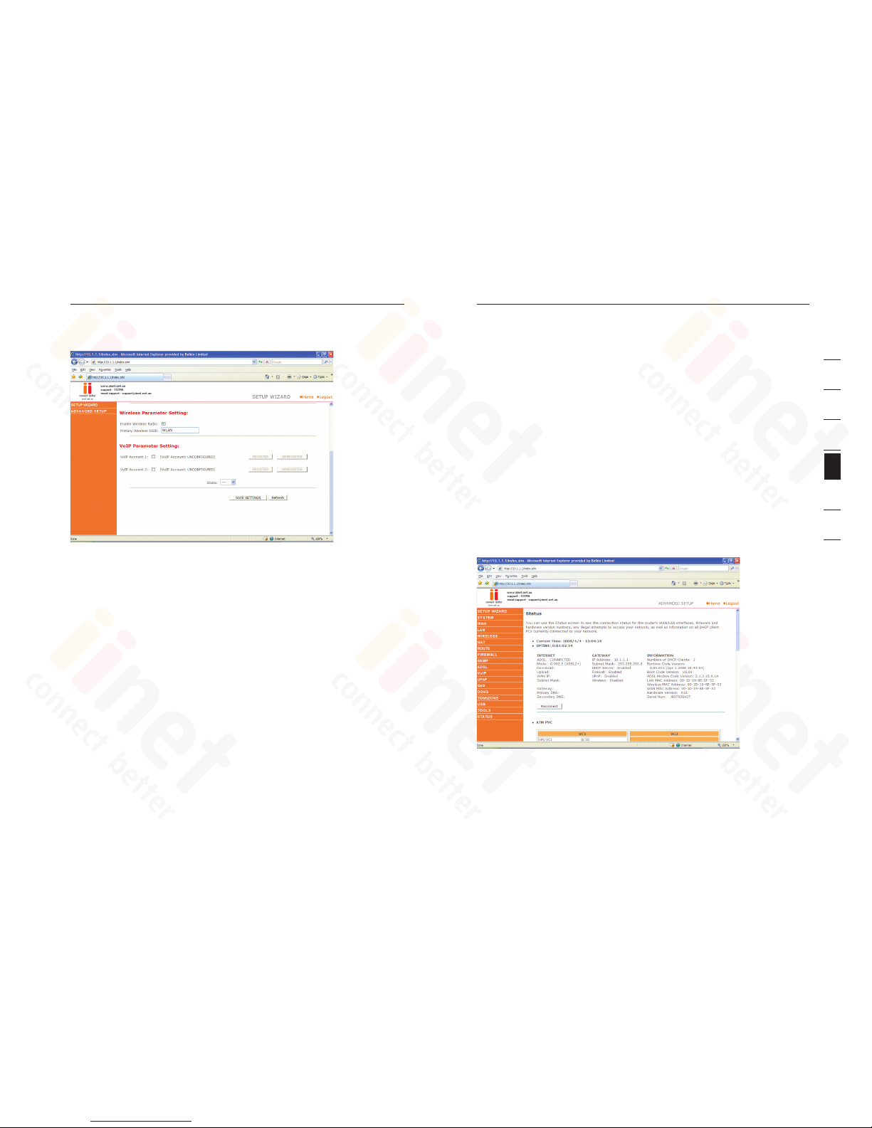
Wir eless Parameter Settin g
Enable Wireless Radio: Enable or disable the routers wireless fu ncti on
Prima ry Wireless SSID: Change the routers primary SSID (wireless name)
VOI P Para met er Set tin g
Firstly you need to tick one of the VoIP account bo xes. For instan ce
if you wish to us e VoIP port 1 o n the back of the mod em then tick the
box for VoIP ac count 1. Then you must enter your VoIP account details
and click on save settings.
Pho ne Num ber : Enter your VoIP account phone number from y our ISP
Pas swo rd: Ent er your VoIP account pa ssword f or you ISP
Reg ist er: Click to register your VoIP account to be ready for use
Unr egister: Un-re gister your VoIP account, so that you can use it on
another VoIP port or device
Cli cki ng the Ho me icon retu rns you to the ho me pag e. The Ma in Menu
lin ks are us ed to navig ate to other menus that display configu ration
par ame ters a nd sta tistics.
Mak ing Co nfi guration Changes
Con fig urable parameter s have a dialog box or a drop -down list.
Onc e a configur ati on cha nge ha s been made on a pag e, cli ck the
“SAVE SETTING S” but ton at the bottom of the p age to make the new
set tin gs act ive.
Not e: To ensure p roper screen ref resh after a command entry, chec k
tha t Inte rnet Explorer 5 .0 is config ured as f ollows: Under the menu
Tools /Internet Options/Gene ral/Temporar y Inte rne t File s/Settings, the
set tin g f or “Ch eck for newer version s of stored pag es” sh ould b e
“Ev ery vi sit to the page.”
The VoIP Router’s ad vanced managemen t inte rfa ce con tains 15 mai n
men u item s as described in the following list.

1716
Advanced Setup Method
Advanced Setup Method
17
sec tion
2
1
3
4
5
6
7
Com mon ly Req uested Fe atures
Not ed in this secti on is a quick reference guide to th e most commo nly
requested advanced features and sh ould s ave yo u the time of
nee din g t o read th e enti re section for the ne ces sary f eatures you are
int erested in.
Set tin g u p Wire less ( Page 3 5)
Thi s sect ion wi ll explai n the basics of turning on th e Wireless
Fun cti ons in yo u Router, if you sh ould require thi s serv ice it is also
sug ges ted yo u l ook into the Setting up Wirele ss Sec urity area as w ell.
Set tin g u p Wire less S ecurity (Page 38)
Thi s sect ion de scr ibes t he 2 forms of Wireles s secu rity a vailable
and allow s you to choose either or both types of sec uri ty in order to
protect your network from outside access .
Opt ion 1: MAC address fi lte ring ( Page 3 7)
MAC Address Filtering uses a u niq ue cod e that each
com put er has in order to create a list of computer s that will
b e allowed onto your network .
Opt ion 2: Wirel ess en cryption (Page 38)
Wireless encryption uses a code m uch li ke a secret
pas swo rd in order to ensure only those compu ter s w hic h
kno w the passw ord are able to ac cess y our ne two rk.
Set tin g u p VoIP (Page 66)
Thi s sect ion wi ll guide you throu gh the basic s of setting up your VoIP
ser vic e o n your network.
Set tin g/Adjustin g Qual ity of Servi ce (Pa ge 74)
If you are having problems with the qu ality of you r Voice servi ce due
to large am ounts of net work t raffic you may adjust your Quality of
Ser vic e i n this section.
Por t Forw arding (Page 52)
Som e programs will require y ou to direct c ertain po rt num bers t o y our
com put er in order to byp ass th e buil t in Fire wal l.
Sho uld th ere be an y furt her fe atu res within the product you would like
to use please find a more extensi ve lis t on the next page.
Men u Desc rip tion
Sys tem (P age 21 )
Wit hin th e Syst em menu you can:
• Set the local time and Time zone as well as Time Sync Server
• Se t the passwo rd for ad ministrator access
• En able remote managem ent an d set the IP a ddress of a PC
tha t will be allowed to access Router remotel y
• Th e IP address of a Domain Name Server
WAN (P age 25 )
• ATM PVC speci fies t he Int ern et con nec tion s etting for a n
ATM ( Asynchrono us Trans fer Mo de) Fr ame work WAN, this
service is used primarily in corporate environments and we
wou ld sug ges t c ont acting your corporate admin ist rator in
orde r to setup these features.
• MAC Address Cloning c an als o b e perf orm ed in this section
sho uld it be requi red by yo ur int ern et servic e provider in o rder to
com ple te the In ter net conne ction.
LAN (Page 30)
The LAN menu itself has a num ber of speci al fie lds in which you
can confi gure information about your Local Area Net work l ike th ose
fun cti ons no ted be low:
• LAN IP Addre ss Set tin gs
• Sub net Ma sk set tin gs
• DCH P Serv er Con trol
• VLA N Port ro uting

1918
Advanced Setup Method
Advanced Setup Method
19
sec tion
2
1
3
4
5
6
7
The LAN Menu a lso ha s 2 sub-m enu s:
• VLA N
Thi s menu allow s you to set t he VLA N rule s for the other ports
and shoul d only be accessed by experienced professional s.
• DHC P Clie nt Lis ts
Thi s menu shows you a l ist of all compute rs cur rently connected
to your netwo rk alo ng wit h their host name and other d etails.
Wir eless (Page 35)
The Wireless Menu all ows yo u t o turn on/off the wirele ss fea tures on
you r router as wel l as having 4 sub-menus :
• Cha nne l & SSID
Thi s area in cludes th e m ost ba sic of ro ute r f unc tions and al lows
you to give a uni que na me to your netwo rk as well as allowing
you to change the channel your wirel ess is running on incase
it is accident all y s har ing th e same chann el as anothe r wireless
app lia nce in th e area .
• Acc ess Co ntrol
Acc ess Co ntrol or MAC ad dress filtering as it is al so kno wn is
an addit ion al lev el of securi ty whi ch all ows yo u to specify which
com put ers are able to lo g into the network via their unique “MAC
Add ress”
• Sec uri ty
The Secur ity me nu allows you access to the o ther f orm of
Wireless Security known as Encryption . This works by using a
num eri cal co de as a key to yo ur net work.
• WDS
WDS stand s for Wireless Di stribution Syste m and is designed
to allow you to add ac cess p oints to you r netw ork . T hes e w ork
as a relay statio n to extend the range of your n etwork.
NAT (Page 43)
• Sha res a sin gle IS P acco unt wi th mul tip le use rs, se ts up Port
for warding.
Rou te (Pa ge 48)
• Set s routing parameters and displays the curre nt routing table.
A rout e dete rmines th e w ay in which the data travels throug h t he
net wor k.
Fir ewall (Page 52)
• Con fig ures a variety of sec urity and sp ecialized funct ions
inc lud ing: A ccess Control , URL blocki ng, In ter net acces s cont rol
sch edu ling, Intruder detecti on, an d DMZ.
SNM P (Pag e 61)
• Com mun ity st ring a nd tra p serv er set ting. SNMP ( Simple
Network Manageme nt Protocol) is us ed by networ k admi nistrators
to manag e atta che d n etw ork de vices.
ADS L (Pag e 63)
• Set s the ADSL opera tio n t ype and shows the ADSL status.
VoIP (Page 66)
• Con fig ures VoIP setting s for the VoIP Router, thi s s ect ion
inv olv es ext ensive and d etailed settings . Plea se read t he ent ire
sec tio n c arefully before att empting any changes.
UPn P (Pag e 73)
• All ows yo u to enable or disable the Universal Plug and P lay
fun cti on. UP nP is design ed to allow users seamle ss Int ern et
ope rat ion wi thout the ne ed to open any ports in th e f irewall.
QoS (Pa ge 74)
• All ows yo u to optimize voice quality by prioriti zing v oice o ver
dat a traffic. QoS (Qu ality of Ser vice) can be set to prioritize
tra ffic for many f eat ures such as VoIP, VPN, nomin ate d IP
Add resses and ports e tc.
DDN S (Pag e 77)
• DDN S (Dyn ami c D oma in Nam e Serv er) al lows y ou to host
ser vic es on the internet via a w eb add ress. For ex ample it wou ld
allow you to host a web pa ge or email server even with a
dyn ami c WAN IP Add ress. In order to use th is fun ction you ma y
nee d to purc hase a ddi tional services like a D omain name f rom a
ser vic e p rovider. This router suppo rts Dy nDN S a nd TZO .
Tomiz one (P age 77 )
• Wit h Tom izone, you s hare your fast Internet connection to make
mon ey. By usi ng Tomizone, you become part of a global netwo rk
of Wi-Fi hotsp ots . A ny rev enue o btained from paying users of
you r Tom izone Wi-Fi Hotspot is s plit w ith yo u and there is no
nee d for you to set up any billing syste m it’s all done
aut oma tically with Tomizone on the global service platform.
More i nformation is a vailable at www.tomizon e.com

2120
Advanced Setup Method
Advanced Setup Method
21
sec tion
2
1
3
4
5
6
7
USB (Page 80)
• You can plug-in your USB hard drive or memory stick and sh are
the se resourc es to your home netwo rk.
Tools (Page 83)
• Con tai ns opt ions t o back up and rest ore th e c urrent
con fig uration, rest ore all c onfigurati on set tin gs to the factory
def aul ts, up date s ystem firmware, or res et the syste m each
und er its own menu.
Sta tus (P age 85 )
• Provides WAN connec tion t ype an d stat us, fi rmw are and
hardware vers ion nu mbe rs, sy stem I P sett ings, as wel l as DHCP,
NAT, and firewal l info rmation.
• Dis pla ys the nu mbe r of attache d clie nts, t he fir mware version s,
the physi cal MA C address fo r e ach me dia inter face, and th e
hardware vers ion an d serial number.
• Sho ws the secur ity and DHCP client log.
Sys tem
Tim e Sett ing s
Set the time zone and t ime se rver f or the VoIP Router. This
inf orm ation is use d for log entries and client access control.
Che ck “En abl e A uto matic Time S erver Maintenanc e” to automatic ally
mai nta in the VoI P Rout er’s system time by sy nchroni zing w ith a
pub lic ti me ser ver over the Internet. Then configure t wo differe nt tim e
ser ver s b y sele cti ng the optio ns in the Primary Server and Seconda ry
Ser ver fi eld s.
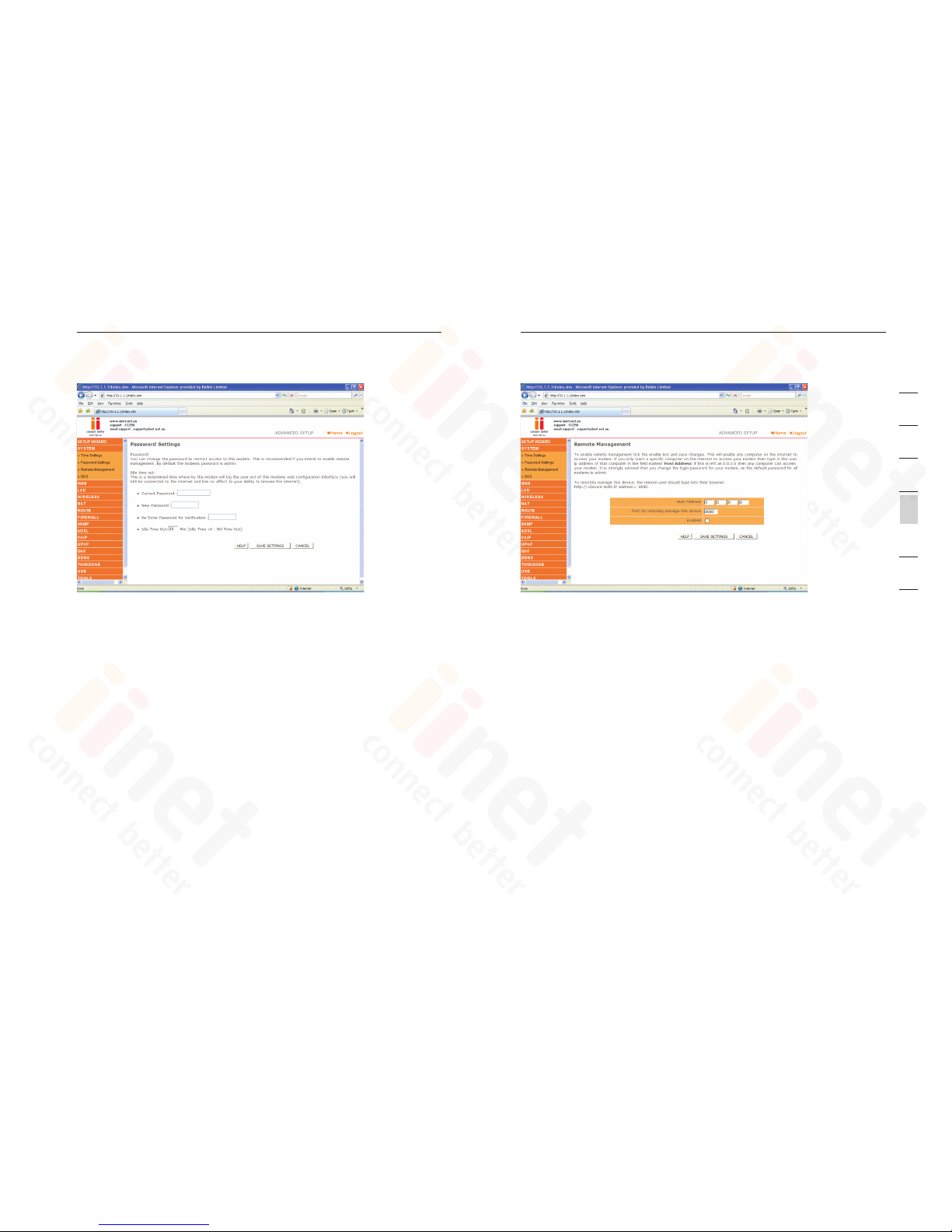
Pas swo rd Settings
Use this page to restr ict ac ces s b ase d o n a password . B y defa ult , t he
pas swo rd is “admin”.
2322
Advanced Setup Method
Advanced Setup Method
23
sec tion
2
1
3
4
5
6
7
Pas swo rds can contain from 3 to12 alphanumeric chara cters which
are ca se sen sitive.
Not e: If your passw ord is lo st, or you cannot gain acces s to the
use r inte rfa ce, press the reset button (colored b lue) o n the rea r
pan el (ho ldi ng it down for at least 20 se con ds) to restore the factory
def aul ts. (B y d efa ult th e pass word is “ admin”)
Ent er a maximum Idle Time Out (in m inutes) t o d efi ne a maxi mum
per iod of time an inactive login session will be maintained . If the
con nec tion i s i nac tive f or lon ger th an the maxim um idl e time , it will be
log ged ou t, and you will have to lo gin to the web managemen t system
aga in. (D efa ult: 1 0 m inu tes)
Rem ote Ma nag ement
By defau lt, ma nag ement access is on ly ava ilable to us ers on your
loc al net wor k. How ever, yo u can also manag e the VoI P Rout er from
out sid e y our ne two rk via re mote m anagement by checking the
Ena ble d c hec k b ox. You can set a H OST AD DRE SS, wh ich wi ll onl y
all ow tha t comp ute r to use rem ote ma nag ement. The p ort fi eld sh ould
be left as the default setting of 8080 unless you n eed to chang e it.
Aft er any chang es are ma de you must click on “Save Settings” to
app ly the m.
Not e: If you check “Enabled” and specify an IP ad dress of 0.0.0.0,
any host can manage the VoIP Router.
For re mote m anagement via a WAN I P address you n eed to
con nec t u sin g p ort 8080. Simpl y ente r WAN IP add ress followed
by :8080 in the address field of your web b rowser, for ex ample,
htt p:/ /212.120.6 8.20:8080. This applies unless you change the port
set tin g, in whi ch case you need to substitute the 8080 f or wha tever
por t you have assig ned .
2524
Advanced Setup Method
Advanced Setup Method
25
sec tion
2
1
3
4
5
6
7
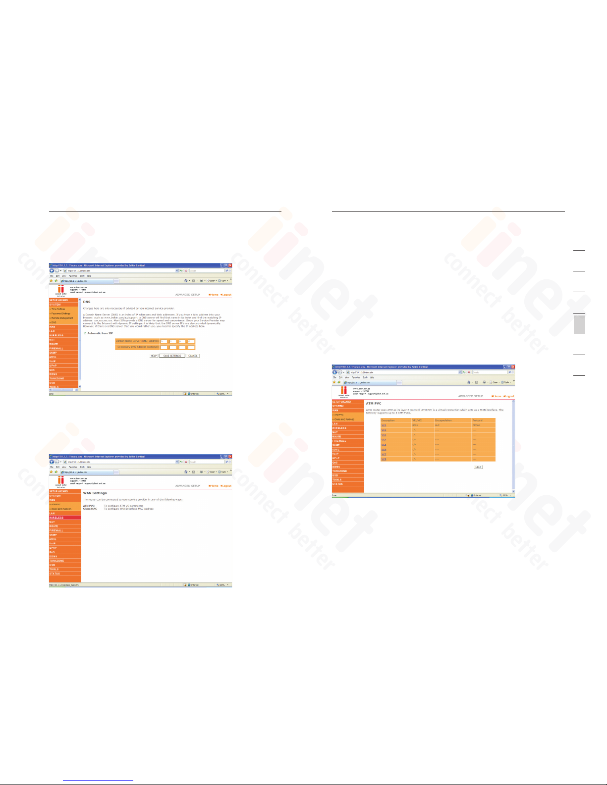
DNS
Dom ain Na me Ser ver s are use d t o map a domain name
(e. g. www. somesite.com) to the equivalent numer ical I P address
(e. g. 64. 147 .25.20). Your ISP should provi de the IP addre ss of one
or more Dom ain Na me Ser ver s. Ent er tho se add resses on this page.
WAN
Spe cif y t he WAN co nnection parameters provided by yo ur Int ern et
Ser vic e P rovider (ISP).
The VoIP Router can be connected to your ISP i n one of the f ollowing
way s:
• ATM PVC
• Clo ne MAC
ATM PVC
The VoIP Router uses ATM as its WAN interface. Click on each ATM
VC for WAN config uration.
Par ame ter De scription
Des cri ption: Click on th e VC to set the v alu es for th e conn ect ion
VPI /VC I: Virtual Path Identifie r (VPI ) and Virtual Circuit Ident ifi er (VC I)
Enc aps ulation: Specifi es how to handle multipl e protocols at the ATM
tra nsp ort la yer
• VC-MUX: Point-to -Po int Protocol over ATM Virtual Circuit
Mul tip lexer (null encapsulat ion) a llo ws onl y o ne protocol running
p er virtua l circuit with less o verhead.

2726
Advanced Setup Method
Advanced Setup Method
27
sec tion
2
1
3
4
5
6
7
• LLC : Poin t-t o-Point Proto col ov er ATM Logical Link Contro l
(LL C) all ows mu lti ple protocols runni ng ove r one virtu al circuit
(us ing sl igh tly mo re overhead).
Pro tocol: Pro toc ol use d for the connecti on
ATM Interface
Cli cki ng on the ATM VC bring s up the following screen. The VoI P
Rou ter us es ATM as its WAN i nterface. Pro toc ols in cluding 1483
Rou tin g, 148 3 B rid ging, MAC En capsulated Routi ng (MER), PPPoA
and PPPoE with LLC-S NAP and VC-MUX encaps ulations are
sup por ted fo r e ach ATM PVC.
Whe n you have finis hed en ter ing yo ur con nection paramete rs, click
“SAVE SETTING S”. You can verif y that you have establis hed an ADSL
con nec tion b y c lic king S tatus at the botto m of the left-hand menu.
See below for a d escription of the parameters.
Par ame ter De scription
Pro tocol
• Dis abl e: Dis ables the co nnection
• 148 3 Brid gin g: Bri dging is a standardized layer 2 t echnology. It
is typic all y u sed in corporat e netw orks t o exte nd the physi cal
reach of a single LAN segment and increase t he num ber of
sta tio ns on a LAN without comprom ising performanc e. Bri dge d
dat a is encapsu lat ed usi ng the RFC14 83 protocol to enable
dat a tran spo rt. Pl ease n ote th at set ting t he router to br idged
mod e disa ble s a ll advanc ed fea tures such as VoIP, Firewall, and
QoS etc
• PPP oA: Po int -to-Point Protocol over ATM is a m ethod of
enc aps ulating data for t ransmissio n to a f ar poi nt
• 148 3 Rout ing : 1 483 Routi ng all ows a simple , low- cost
con nec tion t o t he Internet via a st andard Ethernet port. The
router looks up th e netw ork ad dress for ea ch pac ket se en on
the LAN port. If the ad dress is listed in th e routing table as
loc al, it is filtered . I f the address is lis ted un der th e ADSL port,
it is forwarde d. Or if the address is not found, then i t i s
aut oma tically forwarded t o the defaul t router (i.e., the Vo IP
Rou ter at the head end)
• PPP oE: Po int -to-Point over Ether net is a co mmon c onnection
met hod us ed for xDSL
• MAC Encap sul ated R out ing: If y our AD SL ser vice i s a Bridged
mod e serv ice an d you want to share the connection to multiple
PC’s, p lease select MAC E ncapsulated Routing . MER is a
protocol that allows you do IP ro uting wit h N AT enabled
VPI /VC I
Virtual Path Identifier (VPI) and Virtua l Circuit Identifie r (VCI ). Dat a
flo ws are broken up i nto fi xed le ngth c ell s, eac h o f whic h contain s a
Virtual Path Identifier (VPI) that identifi es the path betwe en two nodes ,
and a Virtua l Circuit Identifier (VCI) that identifi es the data chann el
wit hin th at vir tua l path . Each virtu al circuit maintain s a constant
flo w of cells between the two end p oints. Wh en the re is no dat a to
tra nsm it, em pty ce lls are s ent. W hen da ta nee ds to be transmitt ed, it
is immed iat ely in serted into the ce ll flo ws.
2928
Advanced Setup Method
Advanced Setup Method
29
sec tion
2
1
3
4
5
6
7
Par ame ter De scription
Enc aps ulation
Sho ws the packe t encapsu lation type.
Pac ket en cap sulation specifi es how to handle multiple prot ocols at
the ATM tr ansport layer.
• VC- MUX : P oin t-to-Point Protocol over ATM Virt ual Ci rcuit
Mul tip lexer (null encapsulat ion) a llo ws onl y o ne protocol running
per virtu al circuit w ith le ss ove rhead
• LLC : Poin t-t o-Point Proto col ov er ATM Logical Link Contro l
all ows mu lti ple protocols runni ng ove r one virtu al circuit (using
sli ght ly more overhead)
QoS Class
ATM QoS cl asses including CBR, UBR and VBR.
PCR /SC R/MBS
QoS Param ete rs - PCR (Peak Cell Rate), SCR ( Sustainabl e Cell Rate)
and MBS (Maximu m Burst Size) are con fig urable.
Con nec t Typ e
Set s conn ect ion mo de to always conne cted, automatic or manual
con nec tion.
Idl e Time : Ente r the maximum idle time for t he Int ern et con nection.
(in minut es) Af ter this time has been exceeded the connectio n will be
ter min ated.
Use rname: Enter user name
Pas swo rd: Enter password
Con fir m p ass word: Confirm Passw ord
MTU
Lea ve the Maxim um Transmis sion U nit (M TU) at the default value
(15 00) un les s y ou have a particular rea son to chang e it.
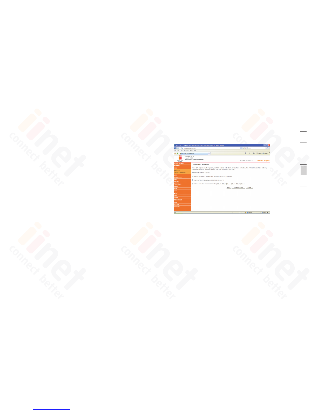
Clo ne MAC Addre ss
Cli cki ng on the Clone MAC Address br ing s up the following screen.
Som e ISPs may requ ire that you register your MAC address wi th
the m. If this is the case, the MA C address of th e VoIP Router must be
cha nge d m anu ally t o the MAC addre ss tha t you have regi stered with
you r ISP.
3130
Advanced Setup Method
Advanced Setup Method
31
sec tion
2
1
3
4
5
6
7
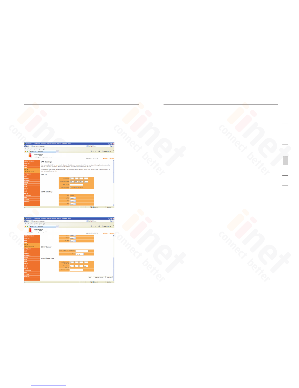
LAN
Use the LAN menu to con figure the LAN IP ad dress and to en able t he
DHC P serv er for dynamic client address allocation .
Par ame ter De scription
LAN IP
IP Addre ss: The I P address of th e VoIP Router
IP Subne t Mask : T he sub net ma sk of the VoIP Router
Hos t Name : If your ISP requires a hostn ame sp eci fied e nter h ere,
oth erw ise le ave bl ank
DHC P Serv er: To dynamic ally a ssign an IP address t o clie nt PCs ,
ena ble th e DHCP (Dynamic Host Config uration Proto col) S erv er
VLA N Bind ing
In this secti on you can assign VLAN’s tha t you have crea ted in the
VLA N page to certain ports such as LAN po rt 1, 2, 3 or 4 and the
WLA N conn ect ion. F or ins tance if you have cre ated a VLAN Bindin g
cal led “Tes t”, an d you want anythin g conn ected to the wireless to be
on that VLAN, then you would change the WLAN setting on thi s p age
from “ Default” to the on e you created called “Test”.
Par ame ter De scription
DHC P SERV ER
DHC P Opti on 60 Vendor ID: If you wi sh you can specify the Name of
you r DHCP Serve r (Option al)
Lea se Tim e: Spe cif y the length of time that the DH CP wil l a ssi gn an
IP address to a compute r for
IP Addre ss Poo l
Sta rt IP: Speci fy the start IP addre ss of the DHCP pool. Do no t
inc lud e t he gat ewa y address of th e Vo IP Rou ter in the client address
poo l. (Se e “TCP /IP Confi guration”) . If you attempt to include the VoIP
Rou ter ga tew ay add ress (10.1.1. 1 by default ) in the DHCP pool, an
error dialog box w ill ap pea r. If you change the p ool ra nge, m ake su re
the first three oc tet s m atc h t he gat ewa y’s IP address , i.e. 10.1. 1.x xx
End IP: Specify the end IP ad dress of the DH CP poo l.
Dom ain Na me: If your netwo rk uses a domain name, enter it here.
Oth erw ise, l eave t his fi eld bl ank
 Loading...