

19 inch Wide Screen
TFT LCD Monitor
USER’S MANUAL

User’s Manual
Before operating the monitor, please read this manual thoroughly. This manual should be
retained for future reference.
FCC Class B Radio Frequency Interference Statement
This equipment has been tested and found to comply with the limits for a Class B digital
device, pursuant to Part 15 of the FCC Rules. These limits are designed to provide
reasonable protection against harmful interference in a residential installation. This
equipment generates, uses and can radiate radio frequency energy, and if not installed and
used in accordance with the instructions, may cause harmful interference to radio
communications. However, there is no guarantee that interference will not occur in a
particular installation. If this equipment does cause harmful interference to radio or
television reception, which can be determined by turning the equipment off and on, the user
is encouraged to try to correct the interference by one or more of the following measures:
Reorient or relocate the receiving antenna.
Increase the separation between the equipment and receiver.
Connect the equipment into an outlet on a circuit different from that to which the
receiver is connected.
Consult the dealer or an experienced radio/TV technician for help.
The device complies with Parts 15 of the FCC Rule. Operation is subject to the following
two conditions﹕ (1) this device may not cause harmful interference﹔ and (2) this device
must accept any interference received, including interference that may cause undesired
operations.
CANADA
This Class B digital apparatus meets all requirements of the Canadian Interference-Causing
Equipment Regulation.
This device complies with requirement of EMC directive 89/336/EEC with regard to
Electromagnetic Compatibility, and 73/23/EEC and 93/68/EEC with regard to Low Voltage
directive.
Socket-outlet shall be near the equipment and shall be accessible.
2

User’s Manual
TCO’99 (FOR OPTIONAL MODEL)
Congratulations!
You have just purchased a TCO’99 approved and labelled product! Your choice has
provided you with a product developed for professional use. Your purchase has also
contributed to reducing the burden on the environment and also to the further development
of environmentally adapted electronics products.
Why do we have environmentally labelled computers?
In many countries, environmental labelling has become an established method for
encouraging the adaptation of goods and services to the environment. With the growing
manufacture and usage of electronic equipment throughout the world, there is a recognized
concern for the materials and substances used by electronic products with regards to their
eventual recycling and disposal. By proper selection of these materials and substances, the
impact on the environment can be minimized.
There are also other characteristics of a computer, such as energy consumption levels, that
are important from the viewpoints of both the work (internal) and natural (external)
environments. Electronic equipment in offices is often left running continuously, resulting in
unnecessary consumption of large amounts of energy and additional power generation.
From the standpoint of carbon dioxide emissions alone, it is vital to save energy.
What does labelling involve?
The product meets the requirements for the TCO’99 scheme which provides for
international and environmental labelling of personal computers and/or displays. The
labelling scheme was developed as a joint effort by the TCO (The Swedish Confederation
of Professional Employees), Svenska Naturskyddsforeningen (The Swedish Society for
Nature Conservation) and Statens Energimyndighet (The Swedish National Energy
Administration).
Approval requirements cover a wide range of issues: ecology, ergonomics, emission of
electrical and magnetical fields, energy consumption and electrical safety.
Ecological criteria impose restrictions on the presence and use of heavy metals, brominated
and chlorinated flame retardants, and other substances. The product must be prepared for
recycling and the manufacturing site(s) shall be certified according to ISO14001 or EMAS
registered.
Energy requirements include a demand that the system unit and/or display, after a certain
period of inactivity, shall reduce its power consumption to a lower level in one or more
stages. The length of time to reactivate the system unit shall be reasonable for the user.
Labelled products must meet strict environmental demands, for example, in respect of the
3

User’s Manual
reduction of electrical and magnetical fields as well as work load and visual ergonomics.
Below you will find a brief summary of the ecological requirements met by this product. The
complete ecological criteria document can be found at TCO Development’s website
http://www.tcodevelopment.com or may be ordered from:
TCO Development
SE-114 94 STOCKHOLM, Sweden
Fax: +46 8 782 92 07
E-mail: development@tco.se
Information regarding TCO’99 approved and labelled products may also be obtained at
http://www.tcodevelopment.com
Ecological requirements
Flame retardants
Flame retardants may be present in printed wiring board laminates, cables, and housings.
Their purpose is to prevent, or at least to delay the spread of fire. Up to 30% by weight of
the plastic in a computer casing can consist of flame retardant substances. Many flame
retardants contain bromine or chlorine, and these flame retardants are chemically related to
PCBs (polychlorinated biphenyls). Both the flame retardants containing bromine or chlorine
and the PCBs are suspected of giving rise to health effects, including reproductive damage
in fish-eating birds and mammals, due to the bio-accumulative* processes when not
disposed of in accordance with strict standards for disposal.
TCO’99 requires that plastic components weighing more than 25 grams shall not contain
flame retardants with organically bound bromine or chlorine. Flame retardants are allowed
in the printed wiring board laminates due to the lack of commercially available alternatives.
Cadmium**
Cadmium is present in rechargeable batteries and in the colour-generating layers of certain
computer displays. TCO’99 requires that batteries, the colour-generating layers of display
screens, and the electrical or electronics components shall not contain any cadmium.
Mercury**
Mercury is sometimes found in batteries, relays and switches. TCO’99 requires that
batteries shall not contain any mercury. It also demands that mercury is not present in any
of the electrical or electronics components associated with the labelled unit. There is
however one exception. Mercury is, for the time being, permitted in the back light system of
flat panel monitors as there today is no commercially available alternative. TCO aims on
removing this exception when a mercury free alternative is available.
Lead**
Lead can be found in picture tubes, display screens, solders and capacitors. TCO’99
permits the use of lead due to the lack of commercially available alternatives, but in future
requirements TCO Development aims at restricting the use of lead.
_____________________________
* Bio-accumulative is defined as substances which accumulate in living organisms.
**Lead, Cadmium and Mercury are heavy metals which are bio-accumulative.
4

User’s Manual
TABLE OF CONTENTS
SAFETY NOTICE........................................................................................... 6
PRECAUTIONS......................................................................................... 6
SPECIAL NOTES ON LCD MONITORS................................................... 7
BEFORE YOU OPERATE THE MONITOR.................................................... 8
FEATURES................................................................................................8
CHECKING THE CONTENTS OF THE PACKAGE..................................8
INSTALLATION INSTRUCTIONS.............................................................9
POWER...................................................................................................... 9
MAKING CONNECTIONS....................................................................... 10
ADJUSTING THE VIEWING ANGLE...................................................... 11
OPERATING INSTRUCTIONS..................................................................... 12
GENERAL INSTRUCTIONS.................................................................... 12
FRONT PANEL CONTROL..................................................................... 13
HOW TO ADJUST A SETTING ............................................................... 14
PLUG AND PLA Y.................................................................................... 16
TECHNICAL SUPPORT (FAQ).................................................................... 17
Q & A FOR GENERAL DEFECTIVE....................................................... 17
ERROR MESSAGE & POSSIBLE SOLUTION....................................... 18
APPENDIX ................................................................................................... 19
SPECIFICATIONS................................................................................... 19
5

User’s Manual
SAFETY NOTICE
1. The changes or modifications not expressly approved by the party responsible for
compliance could void the user's authority to operate the equipment.
2. Shielded interface cables and AC power cord, if any, must be used in order to comply
with the emission limits.
3. The manufacturer is not responsible for any radio or TV interference caused by
unauthorized modification to this equipment. It is the responsibilities of the user to
correct such interference.
WARNING:
To prevent fire or shock hazard, do not expose the monitor to rain or moisture. Dangerously
high voltages are present inside the monitor. Do not open the cabinet. Refer servicing to
qualified personnel only.
PRECAUTIONS
• Do not use the monitor near water, e.g. near a bathtub, washbowl, kitchen sink, laundry
tub, swimming pool or in a wet basement.
• Do not place the monitor on an unstable cart, stand, or table. If the monitor falls, it can
injure a person and cause serious damage to the appliance. Use only a cart or stand
recommended by the manufacturer or sold with the monitor. If you mount the monitor on
a wall or shelf, use a mounting kit approved by the manufacturer and follow the kit
instructions.
• Slots and openings in the back and bottom of the cabinet are provided for ventilation. To
ensure reliable operation of the monitor and to protect it from overheating, be sure these
openings are not blocked or covered. Do not place the monitor on a bed, sofa, rug, or
similar surface. Do not place the monitor near or over a radiator or heat register. Do not
place the monitor in a bookcase or cabinet unless proper ventilation is provided.
• The monitor should be operated only from the type of power source indicated on the
label. If you are not sure of the type of power supplied to your home, consult your dealer
or local power company.
• Unplug the unit during a lightening storm or when it will not be used for long period of
time. This will protect the monitor from damage due to power surges.
• Do not overload power strips and extension cords. Overloading can result in fire or
electric shock.
• Never push any object into the slot on the monitor cabinet. It could short circuit parts
causing a fire or electric shock. Never spill liquids on the monitor.
• Do not attempt to service the monitor by yourself; opening or removing covers can
expose you to dangerous voltages and other hazards. Please refer all servicing to
qualified service personnel.
• To ensure satisfactory operation, use the monitor only with UL listed computers which
have appropriate configured receptacles marked between 100 - 240V AC, Min. 5A.
• The wall socket shall be installed near the equipment and shall be easily accessible.
6
User’s Manual
SPECIAL NOTES ON LCD MONITORS
The following symptoms are normal with LCD monitor and do not indicate a problem.
• Due to the nature of the fluorescent light, the screen may flicker during initial use. Turn
off the Power Switch and then turn it on again to make sure the flicker disappears.
• You may find slightly uneven brightness on the screen depending on the desktop pattern
you use.
• The LCD screen has effective pixels of 99.99% or more. It may include blemishes of
0.01% or less such as a missing pixel or a pixel lit all of the time.
• Due to the nature of the LCD screen, an afterimage of the previous screen may remain
after switching the image, when the same image is displayed for hours. In this case, the
screen is recovered slowly by changing the image or turning off the Power Switch for
hours.
• If the screen suddenly flashes erratically or the backlighting fails, please contact your
dealer or service center for repair. Do not attempt to repair the monitor yourself.
LAMP DISPOSAL
LAMP(S) INSIDE THIS PRODUCT CONTAIN MERCURY AND MUST BE RECYCLED OR
DISPOSED OF ACCORDING TO LOCAL, STATE OR FEDERAL LAWS. FOR MORE
INFORMATION, CONTACT THE ELECTRONIC INDUSTRIES ALLIANCE A T
FOR LAMP SPECIFIC DISPOSAL INFORMATION CHECK
WWW.LAMPRECYCLE.ORG.
WWW.EIAE.ORG.
7

User’s Manual
BEFORE YOU OPERATE THE MONITOR
FEATURES
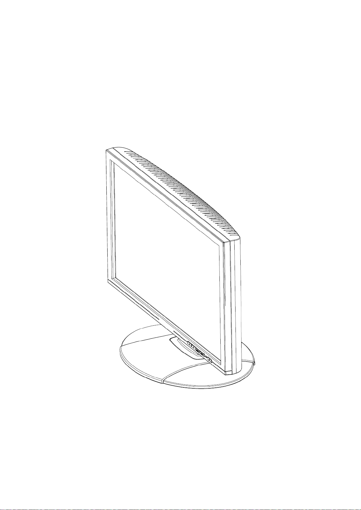
• 19” Wide screen TFT Color LCD Monitor
• Crisp, Clear Display for Windows
• Recommended Resolutions: 1440 X 900 @60Hz
• EPA ENERGY STAR
• Ergonomic Design
• Space Saving, Compact Case Design
CHECKING THE CONTENTS OF THE PACKAGE
The product package should include the following items:
®
LCD Monitor
Screen Base
Cables and User manual
Power Cord VGA Cable Audio Cable
User’s manual Warranty card DVI-D Cable (Optional)
8
User’s Manual
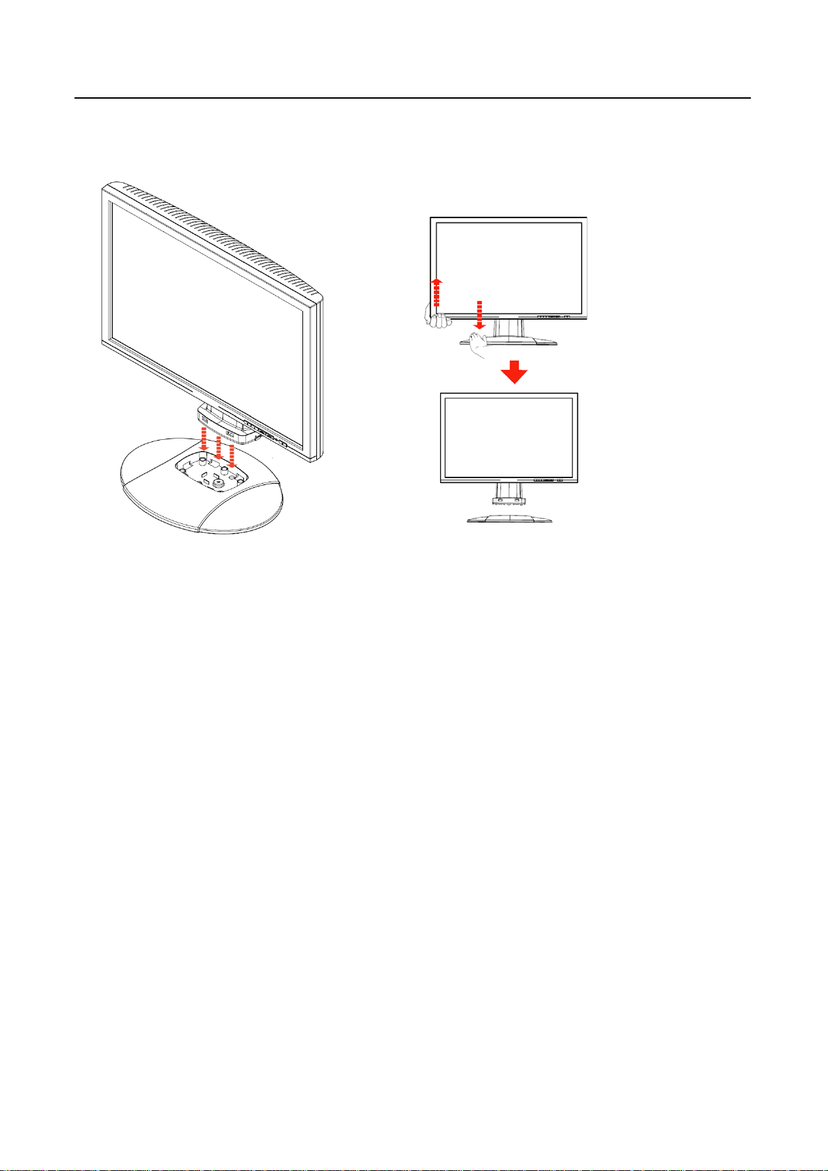
INSTALLATION INSTRUCTIONS
Install Remove
Figure.1. Installing and Removing the Base
INSTALLATION:
1. Align the monitor with the opening in the base.
2. Note that the longer section of the base points forward.
3. Snap the monitor into its base. A clear click sound will affirm that the base is connected
correctly.
4. Verify that the monitor is securely attached to the base by looking at the bottom of the
base and making sure that the clips are fully engaged in the base.
REMOVAL:
1. Flip over the monitor so that it us upside down.
2. Press the 2 clips that hold the monitor in place.
3. Gently press and hold the 2 clips while pulling the base from the monitor unit they are
unattached.
POWER
POWER SOURCE:
1. Make sure that the power cord is the correct type required in your area.
2. This LCD monitor has an Internal universal power supply that allows operation in either
100/120V AC or 220/240V AC voltage area (No user adjustment is required.)
3. Connect the AC-power cord one end to your LCD monitor’s AC-input socket, the other
end to wall-outlet .
9

User’s Manual
MAKING CONNECTIONS
CABLE CONNECTIONS:
Turn off your computer before performing the procedure below.
1. Connect one end of the 15-pin D-Sub cable to the back of the monitor and connect the
other end to the computer’s D-Sub port.
2. Connect one end of the 24-pin DVI-D cable (Dual input mode optional) to the back of the
monitor and connect the other end to the computer’s DVI port.
3. Connect the audio cable between the monitor's audio input and the PC's audio output
(green port).
4. Plug the AC-power cord one end to LCD monitor’s AC input socket, the other end to Wall
outlet.
5. Turn on your monitor and computer.
Figure.2. Connecting Cables
1. VGA Input 2. DVI Input (optional)
3. Audio Input 4. Power AC Input
10

User’s Manual
ADJUSTING THE VIEWING ANGLE
• For optimal viewing it is recommended to look at the full face of the monitor, then adjust
the monitor’s angle to your own preference.
• Hold the stand so you do not topple the monitor when you change the monitor’s angle.
• You are able to adjust the monitor’s angle from -5° to 20°.
Figure.3.
monitor’s angle
NOTES:
• Do not touch the LCD screen when you change the angle. It may cause damage or
break the LCD screen.
•
Be careful not to place fingers or hands near the hinges when tilting the monitor,
otherwise pinching can result.
11

User’s Manual
OPERATING INSTRUCTIONS
GENERAL INSTRUCTIONS
Press the power button to turn the monitor on or off. The other control buttons are located at
front panel of the monitor (See Figure 4). By changing these settings, the picture can be
adjusted to your personal preferences.
• The power cord should be connected.
• Connect the Signal cable from the monitor to the VGA card.
• Press the power button to turn on the monitor position. The power indicator will light up.
EXTERNAL CONTROLS:
1. Menu / Enter 2. Auto Adjustment
3. Volume + 4. Volume -
5. Power Button 6. LED
Figure.4. External Control Button
12

User’s Manual
FRONT PANEL CONTROL
• Power Button:
Press this button to switch ON/OFF of monitor’s power.
• Power Indicator:
Green — Power On mode.
Orange — Power saving mode.
• MENU / ENTER:
1. Activates the OSD menu or confirms adjustments to settings.
2. Exit OSD menu when in volume OSD status.
• Volume < >:
1. Activates the volume control when the OSD is OFF.
2. Navigate through adjustment icons when OSD is ON or adjust a function when
function is activated.
• Auto Adjust button:
When OSD menu is in off status, press this button to activate the Auto Adjustment
function.
(The Auto Adjustment function is used to optimized the H-Position, V-Position, Clock and
Phase.)
NOTES:
• Do not install the monitor in a location near heat sources such as radiators or air dusts,
or in a place subject to direct sunlight, or excessive dust or mechanical vibration or
shock.
• Save the original shipping box and packing materials, as they will come in handy if you
ever have to ship your monitor.
• For maximum protection, repackage your monitor as it was originally packed at the
factory.
• To keep the monitor looking new, periodically clean it with a soft cloth. Stubborn stains
may be removed with a cloth lightly dampened with a mild detergent solution. Never use
strong solvents such as thinner, benzene, or abrasive cleaners, since these will damage
the cabinet. As a safety precaution, always unplug the monitor before cleaning it.
13

User’s Manual
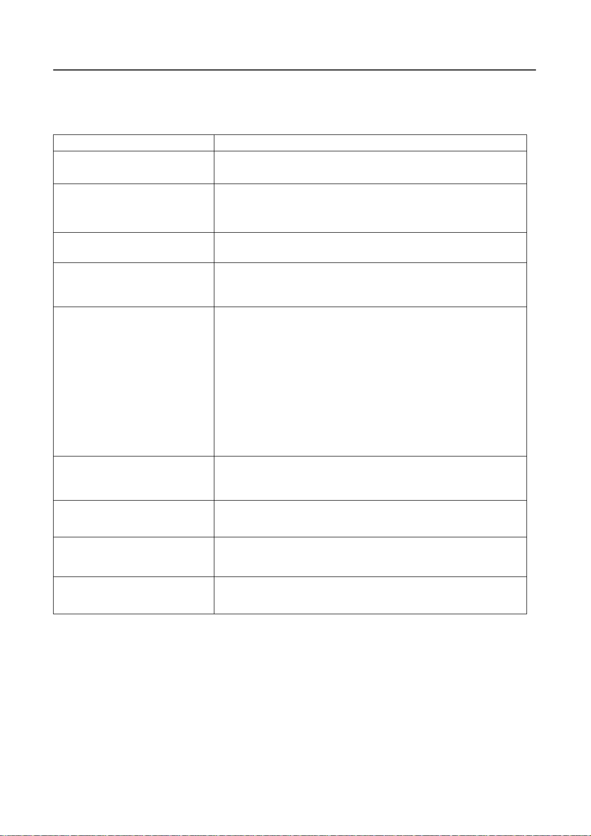
HOW TO ADJUST A SETTING
OSD Diagram OSD Description
Brightness/Contrast:
Brightness: Adjusts brightness by using
the buttons
< or > (② and ⑤ in fig. 4).
Contrast: Adjusts screen contrast by
using the buttons
< or > (② and ⑤ in fig.
4).
Image Control:
Auto Adjustment: Automatically selects
the optimal settings for image parameters
(image position, phase, etc.) by using the
button MENU (① in fig. 4).
H. Position: Controls the picture’s
horizontal position.
V. Position: Controls the picture’s vertical
position.
Clock: Sets up the internal clock. Larger
values make the displayed image appear
wider; smaller values make it appear
compressed.
Phase: Adjusts the internal clock’s time
lag in order to optimize the screen image.
Color:
This menu lets you select a preset color
temperature
(9300K, 6500K) by pressing the OSD
buttons < or > (
② and ⑤ in fig. 4).
Changes to the color temperature take
immediate effect on screen. If you wish to
set individual color values, select the
Custom Color option. Then press the
MENU button (① in fig. 4) to select the
red, green and blue settings and set the
desired value using the OSD buttons < or
② and ⑤ in fig. 4). The current
> (
settings are automatically saved when you
return to the previous level or exit the
OSD menu.
14

OSD Diagram OSD Description
OSD Control:
H. OSD Position: Controls the OSD
menu’s horizontal position.
V. OSD Position: Controls the OSD
menu’s vertical position.
OSD Timeout: Determines how long (in
seconds) the OSD menu waits before
closing automatically after no action has
been performed.
Other:
Language: English. French. German.
Italian. Spanish. Japanese. Portuguese.
Nederlands. Korea. Simplify Chinese.
Traditional Chinese.
Input: Controls the selection of the input
signal. The monitor allows you to make
the following connections: analog graphics
card via the 15-pin mini D-Sub interface,
digital graphics card via the 24-pin DVI-D
interface.
Speaker Volume: Adjusts the monitor
loudspeaker output volume.
User’s Manual
Information: There is an optional OSD
window (on/off) that displays the newly
adjusted screen resolution settings.
15

User’s Manual
PLUG AND PLA Y
Plug & Play DDC2B Feature
This monitor is equipped with VESA DDC2B capabilities according to the VESA DDC
STANDARD. It allows the monitor to inform the host system of its identity and, depending
on the level of DDC used, communicate additional information about its display capabilities.
The DDC2B is a bidirectional data channel based on the I²C protocol. The host can request
EDID information over the DDC2B channel.
THIS MONITOR WILL APPEAR TO BE NON-FUNCTIONAL IF THERE IS NO VIDEO
INPUT SIGNAL. IN ORDER FOR THIS MONITOR TO OPERATE PROPERLY, THERE
MUST BE A VIDEO INPUT SIGNAL.
This monitor meets the Green monitor standards as set by the Video Electronics Standards
Association (VESA) and/or the United States Environmental Protection Agency (EPA) and
The Swedish Confederation Employees (NUTEK). This feature is designed to conserve
electrical energy by reducing power consumption when there is no video-input signal
present. When there is no video input signal this monitor, following a time-out period, will
automatically switch to an OFF mode. This reduces the monitor's internal power supply
consumption. After the video input signal is restored, full power is restored and the display
is automatically redrawn. The appearance is similar to a "Screen Saver" feature except the
display is completely off. The display is restored by pressing a key on the keyboard, or
clicking the mouse.
16
TECHNICAL SUPPORT (FAQ)
Q & A FOR GENERAL DEFECTIVE
User’s Manual
PROBLEM & QUESTION
Power LED is not on
No Plug & Play
Picture is dim, too bright or
fuzzy
Picture bounces or a wave
pattern is present in the
picture
The power LED is ON
(orange) but there’s no
video or no picture.
Missing one of the primary
colors (RED, GREEN, or
BLUE)
Screen image is not centered
POSSIBLE SOLUTION
*Check if the Power Switch is in the ON position
*Power Cord should be connected
*Check if the PC system is Plug & Play compatible
*Check if the Video Card is Plug & Play compatible
*Check if the D-15 plug pin of Video Cable is bent
*Adjust the clock, phase or Contrast and Brightness
Controls.
*Move away electrical devices that may cause electrical
interference.
*Computer Power Switch should be in the ON position.
*Computer Video Card should be snugly seated in its slot
*Make sure monitor’s video cable is properly connected
to the computer.
*Inspect monitor’s video cable and make sure none of
the pins are bent.
*Make sure computer is operational by hitting the CAPS
LOCK key on the keyboard while observing the CAPS
LOCK LED. The LED should either turn ON or OFF after
hitting the CAPS LOCK key.
*Inspect the monitor’s video cable and make sure that
none of the pins are bent.
*Adjust pixel frequency CLOCK and PHASE or press
or sized properly.
Picture has color defects
(white does not look white)
Horizontal or vertical
disturbances on the screen
hot-key (AUTO)
*Adjust RGB color or select color temperature
*Use win 95/98/2000/NT/ME/XP shut-down mode Adjust
CLOCK and PHASE or perform hot- key (AUTO).
17
User’s Manual
ERROR MESSAGE & POSSIBLE SOLUTION
CABLE NOT CONNECTED :
1. Check that the signal-cable is properly connected, If the connector is loose, tighten
the connector’s screws.
2. Check the signal-cable’s connection pins for damage.
INPUT NOT SUPPORT :
Your computer has been set to unsuitable display mode, set the computer to display
mode given in the following table.
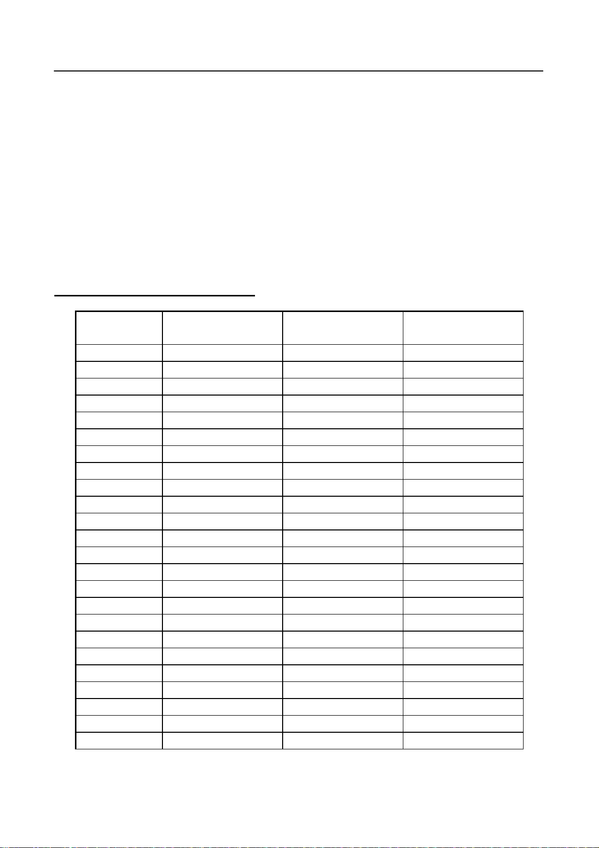
FACTORY PRESET TIMING TABLE:
TIMING MODE
HORIZONTAL
FREQUENCY (kHz)
640x350 VGA-350 31.469 70.087
640x400 VGA-GRAPH 31.469 70.087
640x400 NEC PC9821 31.5 70.15
640x480 VGA-480 31.469 59.94
640x480 APPLE MAC-480 35.00 66.67
640x480 VESA-480-72Hz 37.861 72.809
640x480 VESA-480-75Hz 37.5 75
720x400 VGA-400-TEXT 31.469 70.087
832x624 APPLE MAC-800 49.725 74.55
800x600 SVGA 35.156 56.25
800x600 VESA-600-60Hz 37.879 60.317
800x600 VESA-600-72Hz 48.077 72.188
800x600 VESA-600-75Hz 46.875 75
1024x768 XGA 48.363 60.004
1024x768 COMPAQ-XGA 53.964 66.132
1024x768 VESA-768-70Hz 56.476 70.069
1024x768 VESA-768-75Hz 60.023 75.029
1024x768 APPLE MAC-768 60.24 75.02
1152x864 75Hz 67.50 75.00
1280x960 60Hz 60.00 60.00
1280x1024 VESA-1024-60Hz 64 60
1280x1024 VESA-1024-75Hz 80 75
1440x900 VESA-1440-60Hz 55.935 59.887
1440x900 VESA-1440-75Hz 70.635 75
VERTICAL
FREQUENCY (Hz)
18

APPENDIX
SPECIFICATIONS
User’s Manual
Driving system TFT Color LCD
LCD Panel Size 48.2cm(19.0")
Pixel pitch 0.2835mm(H) x 0.2835mm(V)
Video H-Frequency 31KHz – 80KHz
V-Frequency 56 – 75Hz
Display Colors 16.2M Colors
Max. Resolution 1440 x 900 @75Hz
Plug & Play
EPA ENERGY STAR
®
Input Connector
Maximum Screen Size
ON Mode
OFF Mode
VESA DDC2B
≤ 55W
≤ 1W
D-Sub 15pin
DVI-D 24pin (Dual-Input Model)
Hor. :408.24mm
TM
Ver. :255.15mm
Power Source 90~264VAC,47~63HZ
Environmental
Considerations
Operating Temp: 5° to 40°C
Storage Temp.: -20° to 65°C
Operating Humidity: 20% to 80%
Dimensions
Weight (GW/NW)
446 (W)×362.85 (H)×213.6 (D) mm
17.56”(W)×14.29”(H)×8.4”(D)
5.7 Kg / 4.4K g
12.6 lb/9.7 lb
*** The above specification is subject to actual product specification and is subject to
change without prior notice.
19
 Loading...