

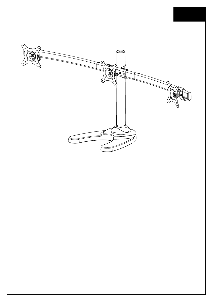
English
Installation Instruction
UNPACKING INSTRUCTIONS
! Carefully open the carton, remove contents and lay out on cardboard or other
protective surface to avoid damage.
! Check package contents against the Supplied Parts List in the next page to assure
that all components were received undamaged. Do not use damaged or defective
parts.
! Carefully read all instructions before attempting installation.
IMPORTANT SAFETY INFORMATION
! Install and operate this device with care. Please read this instruction before
installation, and carefully follow all instructions contained herein. Use proper safety
equipment during installation.
! Please call a qualified installation contractor for help if you don't understand these
directions or have any doubts about the safety of the installation.
Do not use this product for any purpose or in any configuration not explicitly specified
in this instruction. We hereby disclaims any and all liability for injury or damage
arising from incorrect assembly, incorrect mounting, or incorrect use of this product.
1
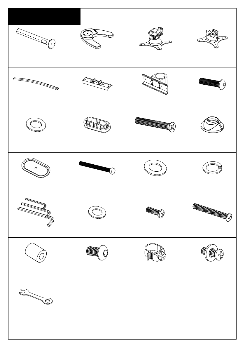
Supplied Parts List
(1) 48mm Pole-a (1) Weighted Base-b
(1) Arm Connect Part-e (1) Arm Clamp-f (4)M6x25 Bolt-g(2) Curved Arm-d
(4)M6 Washer-h (3)M6x29 Bolt-j
(1) -lGrommet Plate (1)M10 Grommet Bolt-m (1)M10 Washer-n1
(2)Arm Plastic Cover-i
(2) Side Vesa Plate
with Slip Set-c1
(1) Middle Vesa
Plate-c2
(1)
Decorative
Cover-k
(1)Spring
Washer-n2
(24)M4 Washer-p(1)Allen Key-o (12)M4x12 Bolt-q (12)M4x30 Bolt-r
(12)M4 Space-s (2)M8x10 Bolt-t (2)Wire Clip-u
(1)Wrench-w
2
(2)M4x16 Bolt
with washer-v

Step 1
Mounting the base according to your requirement
The stand can be used with the weighted
metal base or there is a desk attachment
provided (as drawings on the bottom)
allowing you to mount the stand on a desk.
This is very simple to install and just
requires a hole drilling (10mm diameter) in
your desk and clamping with the bolt and
large washer.
b
Option 2 Option 3
a
Option 1
a
k
j
a
n1
n2
m
k
k
j
b
l
l
n2
n1
m
3
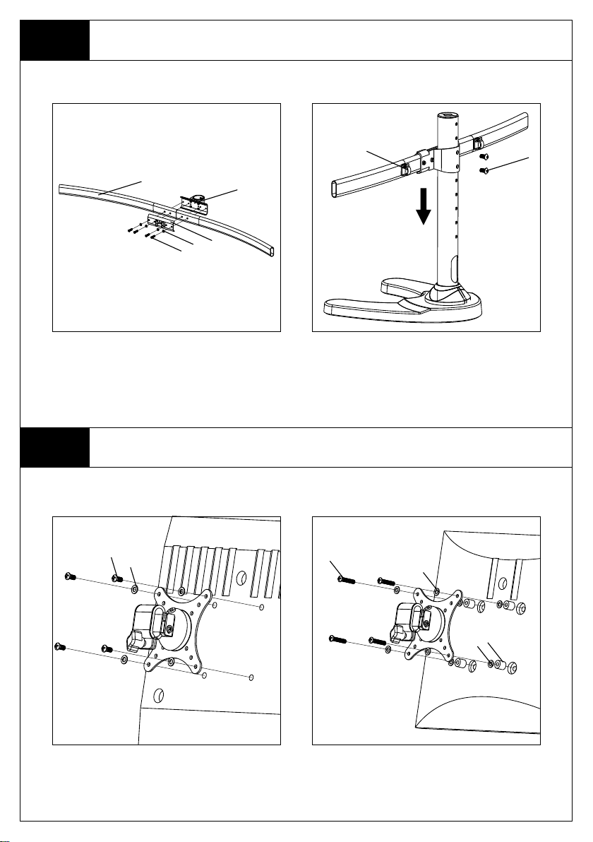
Step 2
Assemble the Arm Sets and Install it on the Pole
d
g
Assemble the curved arm sets as the
diagram above, fasten the M6x25
Bolt-g by provided Allen Key-o.
Step 3
Mount the Monitor to VESA Plate
q
p
f
e
h
u
Insert the curved arm sets to pole,
fasten the M8x10 Bolt-t by provided
Allen Key-o. Install the Wire Clip-u.
t
r
p
For Flat Back Monitor
s
p
For Curved Back Monitor
4
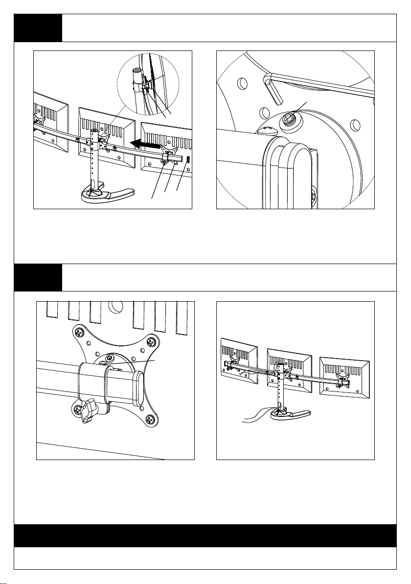
Step 4
i
Plastic Knob
c1
c2
v
Attach the Monitors to Arm Sets and Adjust the Tilting Angle
grub screw
Attaching the monitors to the curved
arm sets, fasten the M4x16 Bolt with
Washer-v, fixing the position by the
plastic knob. Install the Arm Plastic
Cover-i as the above diagram.
Step 5
Adjust the Monitors Level and Manage the Wires
Bolt
By fasten or loosen the bolt on the
above diagram to adjust the level of
each monitor.
Fasten the grub screw to fix the tilting
angle by provided Allen Key-o.
Management the wires as the above
diagram.
Thanks for choosing our products, enjoy the using.
5
 Loading...