

Page 1
www.ihse.de
K48
7 Series
Tempest
User Manual
Edition: 2015-02-25
Draco
KVM Extender
Model:
IHSE GmbH
Maybachstrasse 11
88094 Oberteuringen
Germany
Tel. +49 7546-9248-0
Fax +49 7546-9248-48
Page 2

Draco KVM Extender
Copyright
© 2015. All rights reserved. This information may not be reproduced in any
manner without the prior written consent of the manufacturer.
Information in this document is subject to change without notice.
Trademarks
All trademark and trade names mentioned in this document are
acknowledged to be the property of their respective owners.
Disclaimer
While every precaution has been taken during preparation of this manual,
the manufacturer assumes no liability for errors or omissions. Neither does
the manufacturer assume any liability for damages resulting from the use
of the information contained herein.
The manufacturer reserves the right to change specifications, functions, or
circuitry of the product without notice.
The manufacturer cannot accept liability for damage due to misuse of the
product or due to any other circumstances outside the manufacturer’s
control (whether environmental or installation related). The manufacturer
shall not be liable for any loss, damage, or injury arising directly, indirectly,
incidentally, or consequently from the use of this product.
2
2015-03-05
Page 3

Contents
Contents
1 About This Manual ....................................................................... 5
1.1 Scope .................................................................................. 5
1.2 Validity ................................................................................ 5
1.3 Cautions and Notes............................................................. 5
2 Safety Instructions ....................................................................... 6
3 Description ................................................................................... 7
3.1 Application .......................................................................... 7
3.2 System Overview ................................................................ 7
3.3 Product Range .................................................................... 9
3.4 Upgrade Kits ..................................................................... 10
3.5 Accessories ....................................................................... 10
3.6 Device Views .................................................................... 11
3.6.1 Model K487-1SHS (Single-Head Fiber) .............. 11
3.6.2 Model K487-2S4S (Dual-Head Fiber) ................. 12
3.7 Status LEDs ...................................................................... 13
4 Installation .................................................................................. 14
4.1 Package Contents ............................................................. 14
4.2 System Setup .................................................................... 15
4.2.1 KVM Extender Setup........................................... 15
4.3 Example Applications ........................................................ 16
5 Configuration .............................................................................. 18
5.1 Transmission Parameters ................................................. 18
5.2 DDC Settings .................................................................... 18
5.3 Command Mode................................................................ 19
5.4 USB-HID Ghosting ............................................................ 21
5.5 Configuration File .............................................................. 22
6 Operation .................................................................................... 23
6.1 Download of DDC Information .......................................... 23
7 Specifications ............................................................................. 24
7.1 Interfaces .......................................................................... 24
2015-03-05
3
Page 4

Draco KVM Extender
8 Troubleshooting ......................................................................... 31
9 Technical Support ...................................................................... 33
10 Certificates .................................................................................. 34
11 Glossary ...................................................................................... 37
Pos: 1 /806-IHSE/Zu diesem Handbuc h/ATB_Zu diesem Handbuch @ 5\m od_1278573163276_6.doc @ 4151 0 @ 1222 @ 1
7.1.1 DVI-D Single Link ................................................ 24
7.1.2 USB-HID ............................................................. 24
7.1.3 Fiber SFP Type LC (Interconnect) ...................... 25
7.2 Interconnect Cable ............................................................ 26
7.2.1 Fiber .................................................................... 26
7.3 Supported Peripherals ...................................................... 27
7.3.1 USB-HID Devices ............................................... 27
7.4 Connector Pinouts............................................................. 28
7.5 Power Supply .................................................................... 29
7.6 Environmental Conditions ................................................. 30
7.7 Size ................................................................................... 30
7.8 Shipping Weight ................................................................ 30
8.1 Blank Screen ..................................................................... 31
8.2 USB-HID ........................................................................... 32
9.1 Support Checklist .............................................................. 33
9.2 Shipping Checklist............................................................. 33
10.1 CE Declaration Of Conformity ........................................... 34
10.2 North American Regulatory Compliance ........................... 35
10.3 WEEE ............................................................................... 35
10.4 RoHS/RoHS 2 ................................................................... 35
10.5 Tempest ............................................................................ 35
4
2015-03-05
Page 5
About This Manual
This symbol indicates important information to help you make the best use
1 About This Manual
1.1 Scope
This manual describes how to install your KVM Extender, how to operate it
and how to perform trouble shooting.
1.2 Validity
This manual is valid for all devices listed on the front page. The product
code is printed on the base of the devices.
1.3 Cautions and Notes
The following symbols are used in this manual:
This symbol indicates an important operating instruction that should be
followed to avoid any potential damage to hardware or property, loss of
data, or personal injury.
of this product.
This symbol indicates best practice information to show recommended
and optimal ways to use this product in an efficient way.
Pos: 2 /806-IHSE/Sicherheitshinweise /ATB_Sicherheitshinweise @ 5\mod_ 1278573321245_6.doc @ 41528 @ 1 @ 1
2015-03-05
5
Page 6

Draco KVM Extender
2 Safety Instructions
To ensure reliable and safe long-term operation of your KVM Extender
please note the following guidelines:
Installation
Only use in dry, indoor environments.
The KVM Extender and the power supply units can get warm. Do not
situate them in an enclosed space without any airflow.
Do not place the power supply directly on top of the device.
Do not obscure ventilation holes.
Only use power supplies originally supplied with the product or
manufacturer-approved replacements. Do not use a power supply if it
appears to be defective or has a damaged chassis.
Connect all power supplies to grounded outlets. In each case, ensure
that the ground connection is maintained from the outlet socket
through to the power supply's AC power input.
Do not connect the link interface to any other equipment, particularly
network or telecommunications equipment.
Take any required ESD precautions.
Pos: 3 /806-IHSE/Beschreibung/UEB _Beschreibung @ 5\mod_127857337 9151_6.doc @ 41546 @ 1 @ 1
6
In order to disconnect the device completely from the electric circuit, all
power cables have to be removed.
Repair
Do not attempt to open or repair a power supply unit.
Do not attempt to open or repair the KVM Extender. There are no
user serviceable parts inside.
Please contact your dealer or manufacturer if there is a fault.
2015-03-05
Page 7

Description
3 Description
Pos: 4 /806-IHSE/Beschreibung/Ver wendungszweck/VAR_KVM_Cat X / Gl asfaser @ 5\mod_1278933037886_ 6.doc @ 42823 @ @ 1
3.1 Application
The KVM Extender is used to increase the distance between a source
(computer, CPU) and its console (keyboard, mouse, and other peripheral
devices).
The KVM Extender is designed for use with Cat X (Twisted Pair)
interconnect cables or fiber interconnect cables.
The KVM Extender with Cat X interconnect cables is unsuitable for
connection between buildings where a fiber optic based product should be
used instead.
The KVM Extender with fiber interconnect cables can also be used with
applications in environments which are difficult in electromagnetical
aspects. Electromagnetical interference can limit the maximum distance
und reliability.
Pos: 5 /806-IHSE/Beschreibung/S ystem-Übersicht /VAR_KVM_Single-/Dual-H ead_USB-HID @ 5\mod_12789 33306042_6.doc @ 42842 @ 2 @ 1
3.2 System Overview
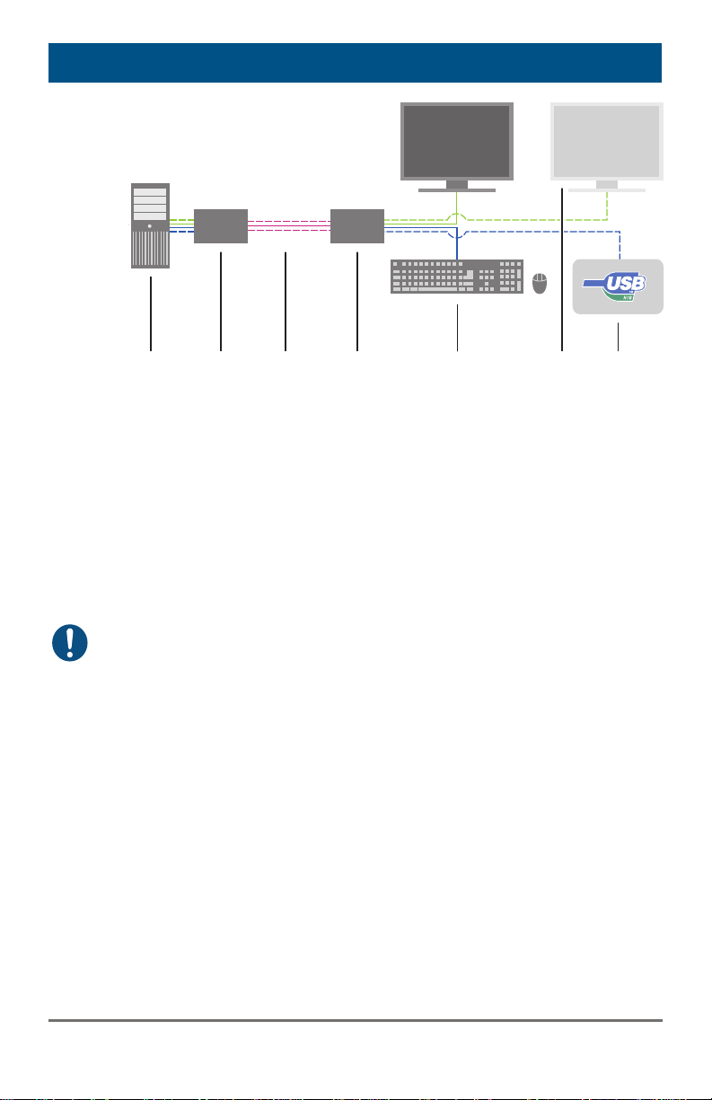
The KVM Extender consists of a CPU Unit and a console unit (CON Unit).
The CPU Unit is connected directly to the source (computer, CPU) using
the supplied cables.
The CON Unit is connected to the console (monitor, keyboard and
mouse).
The CPU Unit and the CON Unit communicate with each other through the
interconnect cables.
2015-03-05
7
Page 8
Draco KVM Extender
1
2
4
5
7
6
3
System Overview
1 Source (computer, CPU)
2 KVM Extender CPU Unit
3 Interconnect cable
4 KVM Extender CON Unit
5 Console (monitor, keyboard, mouse)
6 Second monitor (option, only with Dual-Head devices)
7 USB 2.0 devices (option, only with 2x USB 2.0 devices)
See Chapter 4.3, Page 16 for installation examples.
Pos: 6 /806-IHSE/Beschreibung/Ger ätetypen/477-xx_COMP @ 5\mod_12 91120125984_6.doc @ 44563 @ 2 @ 1
8
2015-03-05
Page 9
Description
3.3 Product Range
Part No. Description
Pos: 7 /806-IHSE/Beschreibung/Einba uoptionen/477-xx @ 5\mod_127893 3558855_6.doc @ 42879 @ @ 1
L487-1SHSTLB
R487-1SHSTLB
L487-2S4STLB
R487-2S4STLB
Fiber devices can be used with Multi-mode and Single-mode cables (see
Chapter 7.2.1, Page 26).
Part numbers for CPU Unit and CON Unit
The part numbers for the CPU Unit and the CON Unit can be derived from
the part number of the complete device.
Example K487-1SHS-TLB:
CPU Unit: L487-1SHS-TLB
CON Unit: R487-1SHS-TLB
All devices of the K487 series are technically compatible to the devices of
the K474 and K477 series.
Single-Head KVM Extender for 1x DVI-D Single Link (up
to 1920x1200), 2x USB-HID
Dual-Head KVM Extender for 2x DVI-D Single Link (up
to 1920x1200), 4x USB-HID
2015-03-05
9
Page 10
Draco KVM Extender
3.4 Upgrade Kits
Model Description
455-4G 19"/1U rack mount kit to mount up to 4 Single-Head devices
455-8G 19"/1U rack mount kit to mount up to 4 Dual-Head devices
455-1K Mounting plate to mount by screws
(Single-Head units)
455-2K Mounting plate to mount by snap on
(Single-Head units)
455-1G Mounting plate to mount by screws
(Dual-Head units)
455-2G Mounting plate to mount by snap on
(Dual-Head units)
The KVM Extenders and the provided power supply units can get warm,
for this reason an installation in closed rooms without air circulation is not
allowed. Please note that you will need at least 0,5 U (height unit) for the
ventilation above the extenders, if you mount them into racks.
Pos: 8 /806-IHSE/Beschreibung/Zube hör/477-xx_COMP @ 5\mod_12911 20662750_6.doc @ 44582 @ 2 @ 1
3.5 Accessories
Model Description
487-PSU5G-TLB
487-IDTLB
Pos: 9 /806-IHSE/Beschreibung/Ger äteansichten/UEB_Geräteansichten @ 5\mod_1278573737808_6.doc @ 4 1654 @ 2 @ 1
International power supply unit 100...240VAC / 5VDC / 3 A
Hirose connector, for test purposes only
DVI-D cable 1.8 m (DVI-D), TEMPEST certified
10
2015-03-05
Page 11
Description
3.6 Device Views
Pos: 10 /806-IHSE/Beschreibung/Gerät eansichten/477-xx/1SHC (Single-He ad Cat X) @ 5\mod_127893428427 6_6.doc @ 42920 @ @ 1
Pos: 11 /806-IHSE/Beschreibung/Gerät eansichten/477-xx/1SHS _1SHX (Singl e-Head Glasfaser) @ 5\mod_12 78934861511_6.doc @ 42940 @ @ 1
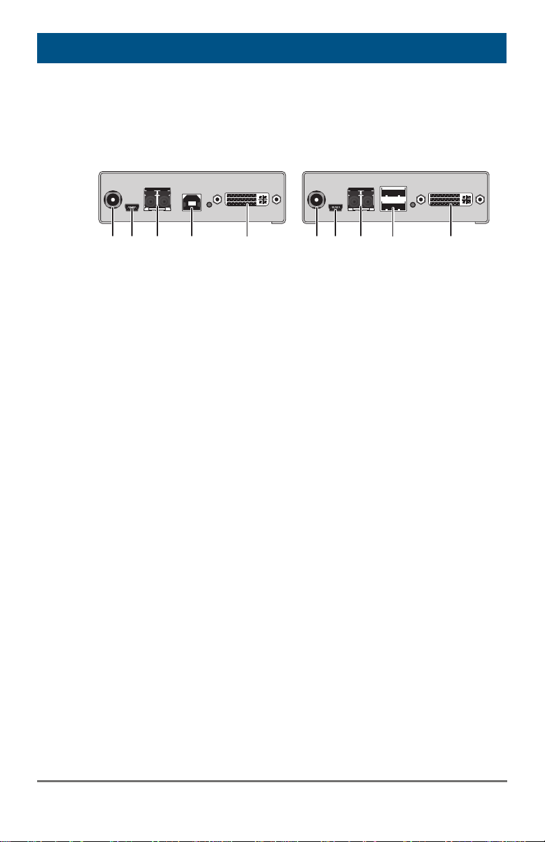
3.6.1 Model K487-1SHS (Single-Head Fiber)
CPU Unit CON Unit
1
Rear View Rear View
1 Connect to 5VDC power
supply
2 Service port
3 Connect to interconnect cable
4 To CPU: USB-HID
5 To CPU: DVI-D
Pos: 12 /806-IHSE/Beschreibung/Gerät eansichten/477-xx_COMP/1SECA (mi t Analog-Audio / Seriell) @ 5\mod _1291647476005_6.doc @ 45820 @ 3 @ 1
3
2
4
5
1
3
2
4
5
1 Connect to 5VDC power
supply
2 Service port
3 Connect to interconnect cable
4 Connect to USB-HID devices
5 Connect to DVI monitor
2015-03-05
11
Page 12
Draco KVM Extender
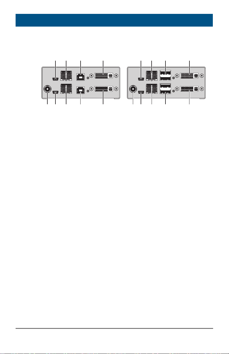
3.6.2 Model K487-2S4S (Dual-Head Fiber)
CPU Unit CON Unit
6
8
7
9
6
7
8
9
Rear View Rear View
1 Connect to 5VDC power
2 Service port 1
3 Connect to interconnect
4 To CPU: USB-HID 1
5 To CPU: DVI-D 1
6 Service port 2
7 Connect to interconnect
8 To CPU: USB-HID 2
9 To CPU: DVI-D 2
Pos: 22 /806-IHSE/Beschreibung/Diagn ose LEDs/477-xx_COMP @ 5\mo d_1291121862656_6.doc @ 44702 @ 23333 @ 1
1
2
supply
cable 1
cable 2
3
4
5
1
3
2
4
5
1 Connect to 5VDC power
supply
2 Service port 1
3 Connect to interconnect
cable 1
4 Connect to USB-HID devices 1
5 Connect to DVI monitor 1
6 Service port 2
7 Connect to interconnect
cable 2
8 Connect to USB-HID devices 2
9 Connect to DVI monitor 2
12
2015-03-05
Page 13
Description
3.7 Status LEDs
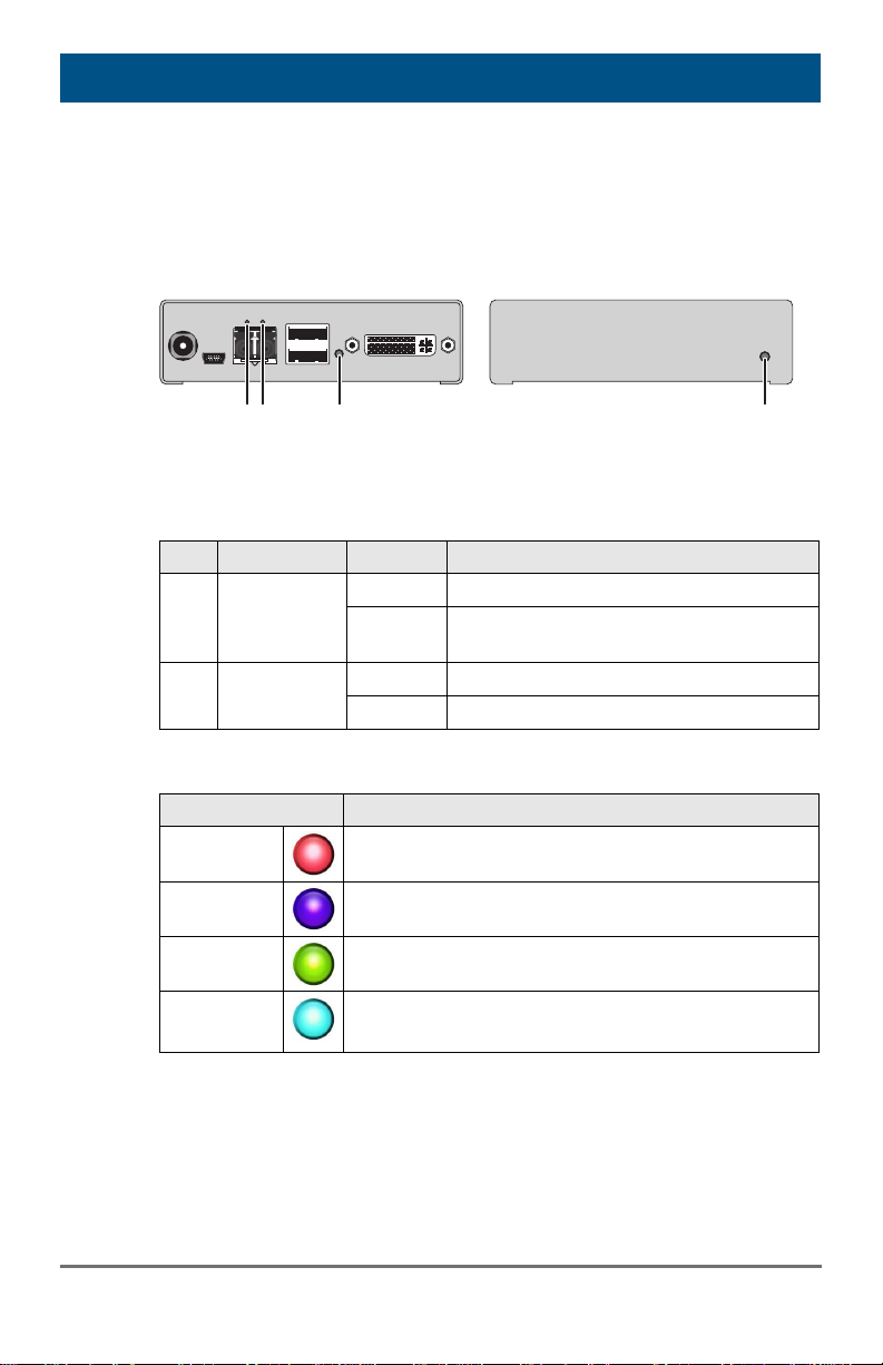
The KVM Extender is fitted with a multi color LED on both sides for overall
status indication and with two further LEDs on the back side for indication
of the connection status.
1
2
3
3
Rear View Front View
LED 1 and 2: Connection Status
Pos. LED Status Description
Failure LED
1
(green)
Status LED
2
(green)
Off Connection available
On or
flashing
Connection failure (flashing for about
20 s following a connection failure)
Flashing No connection via interconnect cable
On Connection available
LED 3: USB and Video Status
LED color Description
Red
Violet
Green
Light Blue
Device ready
Connection and USB signal (interconnect) available
Connection and video signal available
Connection, USB and video signal available
(operating status)
2015-03-05
13
Page 14

Draco KVM Extender
4 Installation
Pos: 24 /806-IHSE/Installation/Lieferu mfang prüfen/477-xx_COMP @ 5\m od_1291123475078_6.doc @ 44730 @ 2 @ 1
4.1 Package Contents
Your extender package contains the following items:
KVM Extender pair (CPU Unit and CON Unit)
Quick Setup
If anything is missing, contact your dealer.
Pos: 25 /806-IHSE/Installation/System anschließen/477-xx_COMP @ 5\mo d_1291123779531_6.doc @ 44749 @ 233 @ 1
14
2015-03-05
Page 15
Installation
4.2 System Setup
First time users are recommended to setup the system with the CPU Unit
and the CON Unit in the same room as a test setup. This will allow you to
identify and solve any cabling problems, and experiment with your system
more conveniently.
Please verify that interconnect cables, interfaces, and handling of the
devices comply with the requirements (see Chapter 7, Page 24).
4.2.1 KVM Extender Setup
1. Switch off all devices.
CON Unit Installation
2. Connect your monitor(s), keyboard and mouse to the CON Unit.
3. Connect the CON Unit with the interconnect cable(s).
4. Connect the 5VDC power supply to the CON Unit.
CPU Unit Installation
5. Connect the source (computer, CPU) with the supplied cables to the
CPU Unit. Please ensure the cables are not strained.
6. Connect the CPU Unit to the interconnect cable(s).
7. Connect the 5VDC power supply to the CPU Unit.
8. Power up the system.
To power up the system, the following sequence is recommended:
Monitor – CON Unit – CPU Unit – source.
2015-03-05
15
Page 16
Draco KVM Extender
1
2
4
5
3
1
2
4
5
7
6
3
4.3 Example Applications
Pos: 27 /806-IHSE/Installation/Installati onsbeispiele/477-xx_COMP @ 5\mo d_1291124264328_6.doc @ 44767 @ @ 1
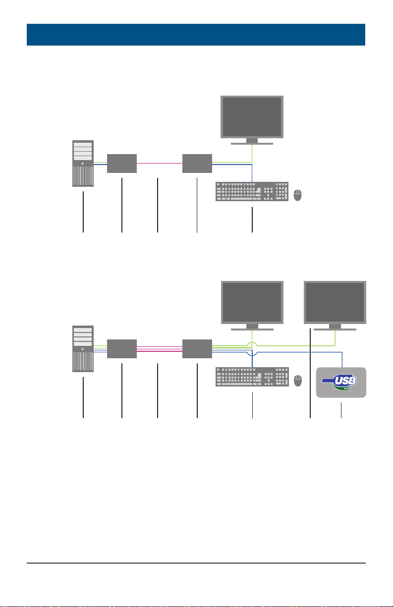
This section illustrates typical installations of KVM Extenders:
KVM Extender (Single-Head)
KVM Extender (Dual-Head with 4x USB-HID)
1 Source (computer, CPU)
2 KVM Extender CPU Unit
3 Interconnect cable
4 KVM Extender CON Unit
5 Console (monitor, keyboard, mouse)
6 Second monitor (option, only with Dual-Head devices)
16
2015-03-05
Page 17

Installation
7 USB 2.0 devices (option, only with 2x USB 2.0 devices)
8 Audio sink (optional, only with devices with Analog Audio / Serial
option or Digital Audio option)
Pos: 28 /806-IHSE/Konfiguration/UEB _Konfiguration @ 5\mod_12785755 17073_6.doc @ 41846 @ 1 @ 1
2015-03-05
17
Page 18

Draco KVM Extender
5 Configuration
Pos: 29 /806-IHSE/Konfiguration/Übertr agungsparameter/477-xx @ 5\ mod_1278937002401_6.doc @ 43075 @ @ 1
5.1 Transmission Parameters
The device operates with a proprietary compression method.
In default configuration, the device adapts dynamically to monitor
resolution and image content. This configuration is suitable for almost all
conditions and should only be modified if image quality is not fully
satisfactory.
In exceptional cases there can appear detached "frame droppings" (loss
of single pictures) or color effects.
Pos: 30 /806-IHSE/Konfiguration/DDC-Ei nstellungen/477-xx @ 5\mod_12 78937107542_6.doc @ 43093 @ 2 @ 1
5.2 DDC Settings
By default, the device transmits the factory preset DDC information to the
CPU. This information is suitable in most cases.
The download of the DDC information of the console monitor can be
performed during normal operation (see Chapter 6.1, Page 23).
For special requirements, DDC information can be retrieved and uploaded
as a binary file at both the CPU Unit and the CON Unit.
Connect your computer with a USB mini cable to the service port of the
CPU Unit or CON Unit.
The data area of the unit is now accessible as a flash drive "Extender".
Uploading DDC Information
Copy the binary file containing your specific DDC information to the flash
drive of the CPU Unit or CON Unit.
The current DDC information is replaced.
Retrieving DDC Information
Copy the file "DDC-EDID.bin" on the flash drive of the CPU Unit to your
computer.
To open the binary file, you have to install a suitable software, e.g.
WinDDCwrite (Download), on your computer.
Reset to Factory DDC Information
Delete the file called "DDC-EDID.bin" on the flash drive of the CPU Unit.
By deleting this file, the factory DDC Information is restored.
18
2015-03-05
Page 19
Configuration
Pos: 31 /806-IHSE/Konfiguration/Ko mmando-Modus/VAR_KVM_USB-HID @ 5\mod_1278577943980_6.doc @ 4 2024 @ 2 @ 1
5.3 Command Mode
During normal use, the console keyboard functions in the usual manner.
However, for all KVM Extenders with USB-HID support, you can set the
keyboard into a Command Mode by using a specific 'Hot Key' sequence.
While in Command Mode, several functions are performed via keyboard
commands. To exit Command Mode, press <Esc>.
While in Command Mode, the LEDs Shift and Scroll on the console
keyboard will flash.
In Command Mode normal keyboard and mouse operation will cease.
Only selected keyboard commands are available.
If there is no keyboard command executed within 10 s after activating
Command Mode, it will be automatically deactivated.
The following table lists the keyboard commands to enter and to exit
Command Mode and to change the 'Hot Key' sequence:
Function Keyboard Command
Enter Command Mode
(default)
Exit Command Mode <Esc>
Change 'Hot Key' sequence <current 'Hot Key'>, <c>,
<Key> + <Key> Press keys simultaneously
<Key>, <Key> Press keys successively
2x <Key> Press key quickly, twice in a row
(similar to a mouse double-click)
2x <Left Shift> ('Hot Key')
<new 'Hot Key' code>, <Enter>
Until 2011-30-09:
<Left Ctrl> + <Left Shift> + <c>,
<'Hot Key' Code>, <Enter>
2015-03-05
19
Page 20
Draco KVM Extender
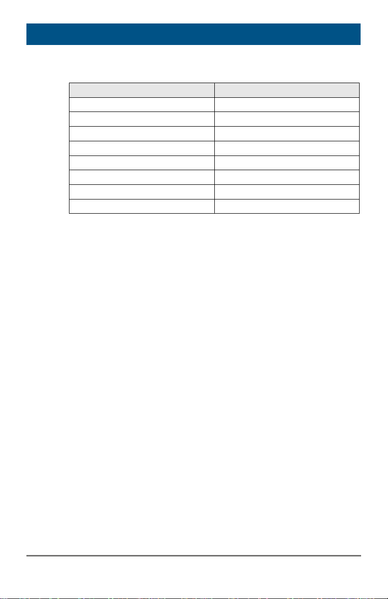
The 'Hot Key' sequence to enter Command Mode can be changed. The
following table lists the 'Hot Key' Codes for the available key sequences:
'Hot Key' Code 'Hot Key'
0 Freely selectable (2012-01-12)
2 2x <Scroll>
3 2x <Left Shift>
4 2x <Left Ctrl>
5 2x <Left Alt>
6 2x <Right Shift>
7 2x <Right Ctrl>
8 2x <Right Alt>
Set freely selectable 'Hot Key' (exemplary)
In order to set a freely selectable 'Hot Key' (e.g. 2x <Space>), use the
following keyboard sequence:
<current 'Hot Key'>, <c>, <0>, <Space>, <Enter>
Reset 'Hot Key'
In order to set a 'Hot Key' back to default settings, press the key
combination <Right Shift> + <Del> within 5 s after switching on the CON
Pos: 32 /806-IHSE/Konfiguration/USB-H ID-Ghosting/K477_USB-HID-Ghosting @ 9\mod_1362404683851_6.doc @ 71192 @ 2 @ 4
unit or plugging in a keyboard.
20
2015-03-05
Page 21
Configuration
5.4 USB-HID Ghosting
This function allows storing the specific keyboard and mice descriptors
(device descriptions) into the CPU unit. This permanent storage prevents
the registration and deregistration process of keyboard and mouse on an
operating system each time, if there is a shared use of a source
(computer, CPU) by two or more consoles within a KVM matrix.
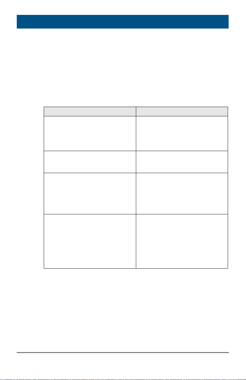
The following table lists the keyboard commands for the configuration of
USB-HID Ghosting:
Function Keyboard Command
Pos: 33 /806-IHSE/Konfiguration/474_ Konfigurationsdatei/474-xx @ 7\m od_1331801555639_6.doc @ 58172 @ 2 @ 1
Writing the device descriptions of
the input devices connected to the
CON Unit into the CPU Unit.
Activating the emulation in the
CPU Unit.
Activating the emulation of
already stored device descriptions
in the CPU Unit
Deactivating the emulation of
active device descriptions in the
CPU Unit. The input devices
connected to the CON Unit will be
now passed transparently to the
source (computer, CPU).
Deactivating the emulation of
active device descriptions in the
CPU Unit. Deleting the
descriptions out of the CPU Unit.
The input devices connected to
the CON Unit will be now passed
transparently to the source
(computer, CPU).
<'Hot Key'>, <h>, <w>, <Enter>
<'Hot Key'>, <h>, <e>, <Enter>
<'Hot Key', <h>, <d>, <Enter>
<'Hot Key', <h>, <r>, <Enter>
2015-03-05
21
Page 22

Draco KVM Extender
5.5 Configuration File
The KVM Extender contains a configuration file (Config.txt) to set specific
parameters and to read out device and video information. You can find it
on the flash drive of the KVM Extender. The flash drive can be opened by
a mini USB connection to a computer.
The configuration file can be edited with all common text editors.
The individual settings of the parameters are described in the respective
chapters.
Pos: 34 /806-IHSE/Betrieb/UEB_Betri eb @ 5\mod_1278577614980_6.doc @ 41970 @ 1 @ 1
22
2015-03-05
Page 23

Operation
6 Operation
Pos: 35 /806-IHSE/Betrieb/Laden von DDC-Informationen/477-xx @ 5\mo d_1278937455136_6.doc @ 43130 @ 2 @ 1
6.1 Download of DDC Information
By default, data from the internal DDC list is reported to the source
(computer, CPU). If these settings do not lead to a satisfying result, the
DDC information of the console monitor can be downloaded and stored
internally. The devices have to be configured accordingly (see
Chapter 5.2, Page 18).
On all KVM Extenders with USB-HID support, the user can load the DDC
information of the console monitor via keyboard command under operating
conditions.
1. Enter Command Mode with the 'Hot Key' (see Chapter 5.2, Page 18).
2. Press the key <a> to download the DDC information of the console
monitor.
The screen goes black for a short time.
At the same time Command Mode is closed and the keyboard LEDs
return to previous status.
The video mode has been readjusted. Screen quality should be
optimal. The CPU should now show the console monitor as the
current screen, together with the available video resolutions.
The DDC information of the console monitor was loaded once.
Reloading is possible by repeating the operation.
Pos: 36 /806-IHSE/Technische Date n/UEB_Technische Daten @ 5\mod_ 1278578165261_6.doc @ 42096 @ 1 @ 1
2015-03-05
23
Page 24

Draco KVM Extender
7 Specifications
Pos: 37 /806-IHSE/Technische Date n/Schnittstellen/UEB_Schnittstellen @ 5\mod_1278578201870_6.doc @ 4 2114 @ 2 @ 1
7.1 Interfaces
Pos: 38 /806-IHSE/Technische Date n/Schnittstellen/DVI-D-Single-Link @ 5\ mod_1278578254058_6.doc @ 42 132 @ 3 @ 1
7.1.1 DVI-D Single Link
The video interface supports the DVI-D protocol. All signals that comply to
DVI-D Single Link norm can be transmitted. This includes e.g. monitor
resolutions such as 1920x1200@60Hz, Full HD (1080p) or 2K HD (up to
2048x1152). Data rate is limited to 165 MPixel/s.
Pos: 39 /806-IHSE/Technische Date n/Schnittstellen/DVI-I-Single-Link @ 5\ mod_1291127308328_6.doc @ 44809 @ @ 1
Pos: 40 /806-IHSE/Technische Date n/Schnittstellen/USB-HID @ 5\mod_12 78578292214_6.doc @ 42150 @ 3 @ 1
7.1.2 USB-HID
Pos: 41 /806-IHSE/Technische Date n/Schnittstellen/USB 2.0 (transparent) @ 5\mod_1278578316386_6.doc @ 42168 @ @ 1
Pos: 43 /806-IHSE/Technische Date n/Schnittstellen/Glasfaser SFP Typ LC @ 5\mod_1278937700855_6.doc @ 43149 @ 3 @ 1
Our devices with USB-HID interface support a maximum of two devices
with USB-HID protocol. Each USB-HID port provides a maximum current
of 100 mA.
Keyboard
Compatible with most USB keyboards. Certain keyboards with additional
functions may require custom firmware to operate. Keyboards with an
integral USB Hub (Mac keyboards e.g.) are also supported.
Mouse
Compatible with most 2-button, 3-button and scroll mice.
Other USB-HID devices
The proprietary USB emulation also supports certain other USB-HID
devices, such as specific touch screens, graphic tablets, barcode
scanners or special keyboards. Support cannot be guaranteed, however,
for every USB-HID device.
Only two USB-HID devices are supported concurrently, such as keyboard
and mouse or keyboard and touch screen. A hub is allowed, but it does
not increase the number of HID devices allowed.
To support other USB 'non-HID' devices, such as scanners, web cams or
memory devices, choose our devices with transparent USB support.
24
2015-03-05
Page 25

Specifications
7.1.3 Fiber SFP Type LC (Interconnect)
The communication of fiber devices is performed via Gigabit SFPs that
have to be connected to suitable fibers fitted with connectors type LC ().
The correct function of the device can only be guaranteed with SFPs
provided by the manufacturer.
SFP modules can be damaged by electrostatic discharge (ESD).
Please consider ESD handling specifications.
Pos: 44 /806-IHSE/Technische Date n/Schnittstellen/Serielle Schnittstelle @ 5\mod_1291127444390_6.doc @ 44828 @ @ 1
Pos: 45 /806-IHSE/Technische Date n/Schnittstellen/Analoge Audio-Schnitts telle @ 5\mod_1291127716734_6.d oc @ 44846 @ @ 1
Pos: 47 /806-IHSE/Technische Date n/Verbindungskabel/UEB_Verbindung skabel @ 5\mod_1279191107845_6. doc @ 43870 @ 2 @ 1
2015-03-05
25
Page 26
Draco KVM Extender
7.2 Interconnect Cable
Pos: 48 /806-IHSE/Technische Date n/Verbindungskabel/Verbindungskab el (Cat X) @ 5\mod_1278578406026_ 6.doc @ 42205 @ 3 @ 1
7.2.1 Fiber
A point-to-point connection is necessary. Operation with multiple patch
panels is allowed. Routing over active network components, such as
Ethernet Hubs, Switches or Routers, is not allowed.
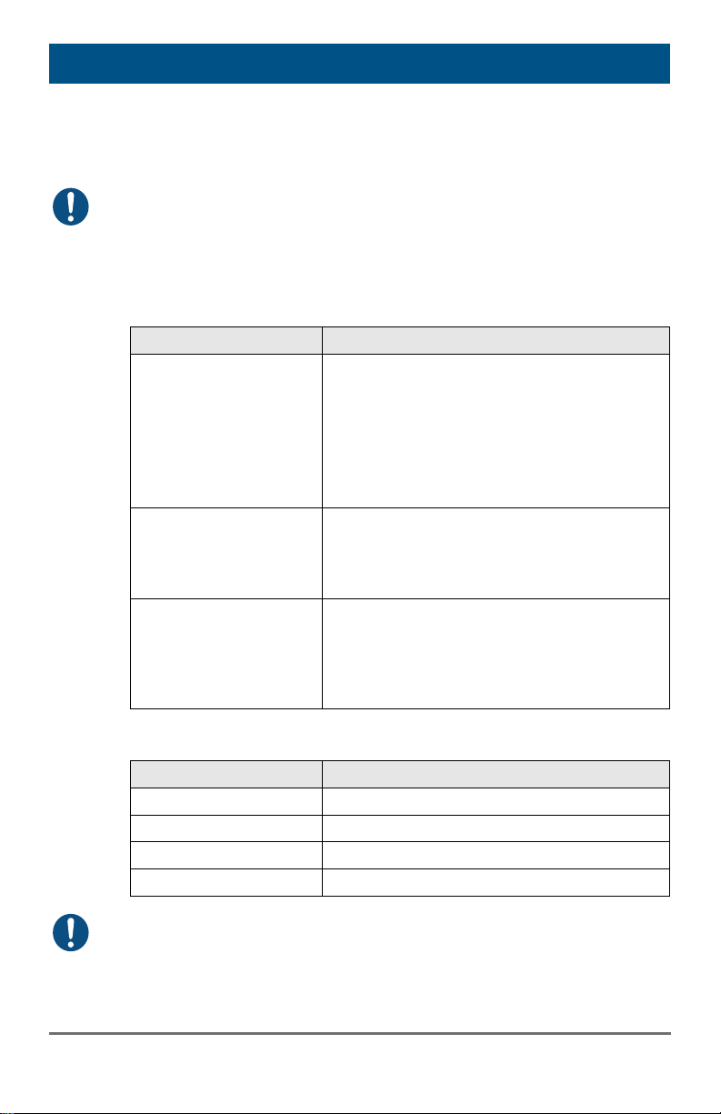
Type of Interconnect Cable
(Cable notations according to VDE)
Type of cable Specifications
Single-mode 9µm Two fibers 9µm
I-V(ZN)H 2E9 (in-house patch cable)
I-V(ZN)HH 2E9 (in-house breakout cable)
I/AD(ZN)H 4E9 (in-house or outdoor
A/DQ(ZN)B2Y 4G9 (outdoor cable, with
Multi-mode 50µm Two fibers 50µm
I-V(ZN)H 2G50 (in-house patch cable)
I/AD(ZN)H 4G50 (in-house or outdoor
Multi-mode 62.5µm Two fibers 62.5µm
I-V(ZN)HH 2G62,5 (in-house breakout
A/DQ(ZN)B2Y 4G62,5 (outdoor cable,
Maximum Acceptable Cable Length
breakout cable, resistant)
protection against rodents)
breakout cable, resistant)
cable)
with protection against rodents)
Pos: 51 /806-IHSE/Technische Date n/Verbindungskabel/Verbindungskab el (LWL)_Steckverbinder 477-xx @ 5\ mod_1278954447542_6.doc @ 4374 0 @ @ 1
26
Type of cable Maximum Acceptable Cable Length
Single-mode 9µm 10,000 m (32,800 ft)
Multi-mode 50µm (OM3) 1,000 m (3,280 ft)
Multi-mode 50µm 400 m (1,300 ft)
Multi-mode 62.5µm 200 m (650 ft)
If you use single-mode SFPs with multi-mode fibers, you normally can
double the maximum acceptable cable length.
2015-03-05
Page 27
Specifications
Type of Connector
Connector
Pos: 52 /806-IHSE/Technische Date n/Unterstützte Peripherie/UEB_Unterst ützte Peripherie @ 5\mod_12785784 78761_6.doc @ 42242 @ 2 @ 1
LC Connector
7.3 Supported Peripherals
Pos: 53 /806-IHSE/Technische Date n/Unterstützte Peripherie/USB-HID-G eräte @ 5\mod_1278578523558_6.doc @ 42260 @ @ 1
7.3.1 USB-HID Devices
The KVM Extender will support most USB-HID devices, including the vast
majority of keyboards and mice currently on the market. Many other kinds
of HID devices such as bar-code scanners and touch screens may also be
compatible
It is not possible to guarantee support for all available USB-HID devices.
In certain cases, custom firmware may be required.
USB-HID (and other) devices that are not supported as standard will
normally operate with our devices featuring transparent USB support.
Please note that concurrent operation of more than two USB-HID devices
is not possible even if you use a USB hub.
Pos: 54 /806-IHSE/Technische Date n/Unterstützte Peripherie/USB-2.0-Gerät e @ 5\mod_1278578553933_6.doc @ 42278 @ @ 1
2015-03-05
27
Page 28
Draco KVM Extender
132
4
7.4 Connector Pinouts
Pos: 56 /806-IHSE/Technische Date n/Pinbelegungen/Buchse DVI-D Single-Li nk @ 5\mod_1278578723073_ 6.doc @ 42333 @ @ 1
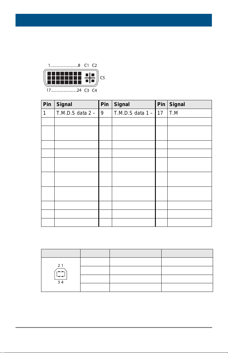
Connector DVI-D Single-Link
1.............................8 C1 C2
C5
Pin Signal Pin Signal Pin Signal
1 T.M.D.S data 2 – 9 T.M.D.S data 1 – 17 T.M.D.S data 0 –
2 T.M.D.S data 2 + 10 T.M.D.S data 1 + 18 T.M.D.S data 0 +
3 T.M.D.S data 2
4 n.c. 12 n.c. 20 n.c.
5 n.c. 13 n.c. 21 n.c.
6 DDC Input (SCL) 14 +5VDC high
7 DDC Output
8 Internal use 16 Hot Plug
C1 Internal use C3 Internal use
C2 n.c. C5 GND C4 Internal use
Pos: 57 /806-IHSE/Technische Date n/Pinbelegungen/Buchse DVI-I Single- Link @ 5\mod_1291134800734_6.do c @ 45577 @ @ 1
Pos: 58 /806-IHSE/Technische Date n/Pinbelegungen/Buchse USB Typ B @ 5\mod_1278578750464_6.doc @ 4 2351 @ @ 1
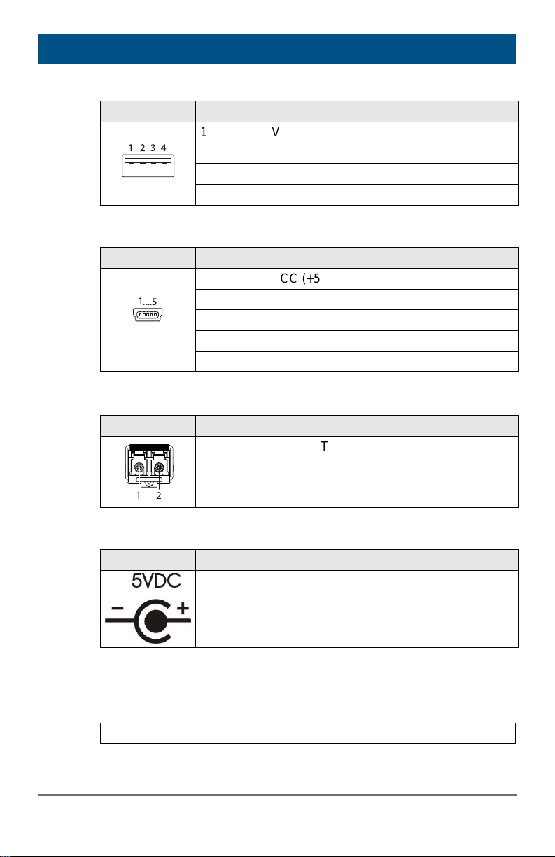
Connector USB Type B
Picture Pin Signal Color
Pos: 59 /806-IHSE/Technische Date n/Pinbelegungen/Buchse USB Typ A @ 5\mod_1278578771214_6.doc @ 4 2369 @ @ 1
17...........................24
GND
(SDA)
C3 C4
11 T.M.D.S data 1
GND
19 T.M.D.S data 0
GND
22 T.M.D.S clock
impedance
GND
15 GND 23 T.M.D.S clock +
24 T.M.D.S clock –
recognition
1 VCC (+5VDC) Red
2 Data – White
3 Data + Green
4 GND Black
28
2015-03-05
Page 29
Specifications
1
3
2
4
....5
1
1 2
Connector USB Type A
Picture Pin Signal Color
1 VCC (+5VDC) Red
2 Data – White
3 Data + Green
4 GND Black
Pos: 60 /806-IHSE/Technische Date n/Pinbelegungen/Buchse Mini-USB Typ B @ 5\mod_1278578794167_6. doc @ 42387 @ @ 1
Pos: 61 /806-IHSE/Technische Date n/Pinbelegungen/RJ45 @ 5\mod_127 8578820011_6.doc @ 42405 @ @
Pos: 62 /806-IHSE/Technische Date n/Pinbelegungen/Glasfaser SFP Typ LC @ 5\mod_1278938501151_6.doc @ 43210 @ @ 1
Connector Mini USB Type B
Picture Pin Signal Color
1 VCC (+5VDC) Red
2 Data – White
3 Data + Green
4 n.c. –
5 GND Black
Fiber SFP Typ LC
Picture Diode Signal
1 Data OUT
Pos: 63 /806-IHSE/Technische Date n/Pinbelegungen/Stromversorgung @ 5 \mod_1278578849183_6.doc @ 42423 @ @ 1
Power Supply
Picture Pin Signal
Pos: 64 /806-IHSE/Technische Date n/Pinbelegungen/D-Sub 9 (Seriell) @ 5\ mod_1291128631437_6.doc @ 44 882 @ @ 1
Pos: 69 /806-IHSE/Technische Date n/Stromversorgung/477-xx_COMP @ 5 \mod_1291129232140_6.doc @ 44 977 @ 2 @ 1
7.5 Power Supply
Voltage
2015-03-05
2 Data IN
Inside VCC (+5VDC)
Outside GND
5VDC
29
Page 30
Draco KVM Extender
Voltage
Power Requirement
(per Unit)
Pos: 70 /806-IHSE/Technische Date n/Einsatzbedingungen/ATB_Einsatzbe dingungen @ 5\mod_12785789800 26_6.doc @ 42480 @ 2 @ 1
5VDC
Single-Head devices: max. 800 mA
Dual-Head devices: max. 1,600 mA
7.6 Environmental Conditions
Pos: 71 /806-IHSE/Technische Date n/Abmessungen/477-xx_COMP @ 5\ mod_1291129370218_6.doc @ 4499 6 @ @ 1
Operating Temperature
Storage Temperature
Relative Humidity
41 to 113°F (5 to 45°C)
–13 to 140°F (–25 to 60°C)
Max. 80% non-condensing
7.7 Size
Single-Head Devices
CPU Unit / CON Unit
Shipping Box
103 x 143 x 29 mm (4" x 5.6" x 1.1")
210 x 140 x 165 mm (8.3" x 5.5" x 6.5")
Dual-Head Devices and Devices with Optional Modules
CPU Unit / CON Unit
Shipping Box
Pos: 72 /806-IHSE/Technische Date n/Transportgewicht /477-xx_COMP @ 5\mod_1291129453984_6.doc @ 4 5015 @ @ 1
103 x 143 x 43 mm (4" x 5.6" x 1.7")
460 x 250 x 120 mm (18.1" x 9.8" x 4.7")
7.8 Shipping Weight
Single-Head Devices
Dual-Head Devices and Devices with Optional Modules
Pos: 73 /806-IHSE/Hilfe im Problemfall/U EB_Hilfe im Problemfall @ 5\mod _1278579113839_6.doc @ 42536 @ 1 @ 1
30
CPU Unit / CON Unit
Shipping Box
CPU Unit / CON Unit
Shipping Box
0.3 kg (0.7 lb)
1.8 kg (4.0 lb)
0.4 kg (0.9 lb)
2.3 kg (5.1 lb)
2015-03-05
Page 31
Troubleshooting
8 Troubleshooting
Pos: 74 /806-IHSE/Hilfe im Problemfall/ Bildausfall/477-xx @ 5\mod_127893 8890573_6.doc @ 43288 @ @ 1
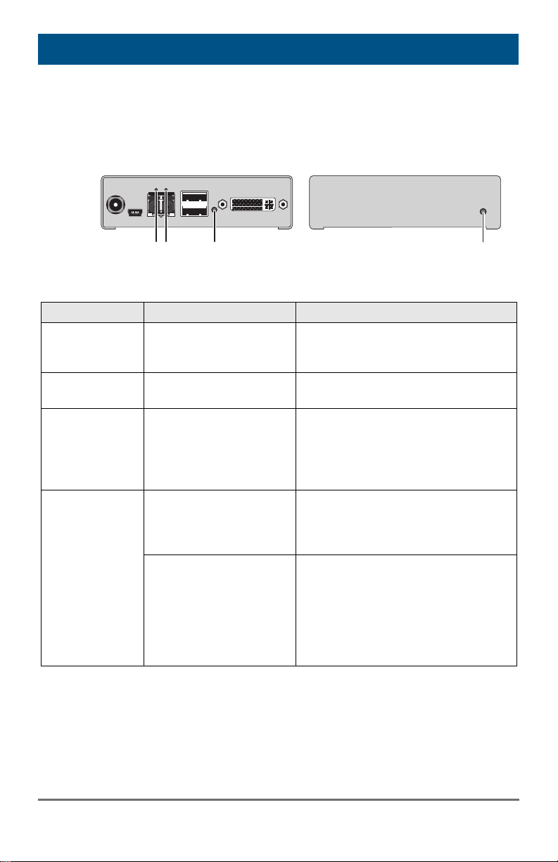
8.1 Blank Screen
1
2
3
Rear View Front View
Diagnosis Possible Reason Measure
LED 3 off
Power supply Check power supply units and
the connection to the power
network.
LED 1 on or
LED 2 off
CPU Unit:
LED 3 red or
yellow
Connection between
CON Unit and CPU Unit
No video signal detected
by source (computer,
CPU)
Check interconnect cables and
connections.
Check DVI-D cable to CPU
Download DDC information from
console monitors (see
Chapter 6.1, Page 23).
Reboot CPU if necessary.
CON Unit:
LED 3 red or
yellow
No monitor detected Check connection, length and
quality of the DVI-D cable to
monitor, tighten cable
thumbscrews.
No video signal detected
from CPU Unit
Check connection, length and
quality of interconnect cables
between the units.
Download DDC information from
console monitors (see
Chapter 6.1, Page 23).
Reboot CPU if necessary.
Pos: 75 /806-IHSE/Hilfe im Problemfall/ Störung am USB-HID-Anschluss/477- xx @ 5\mod_1278938993948_6. doc @ 43307 @ @ 1
3
2015-03-05
31
Page 32
Draco KVM Extender
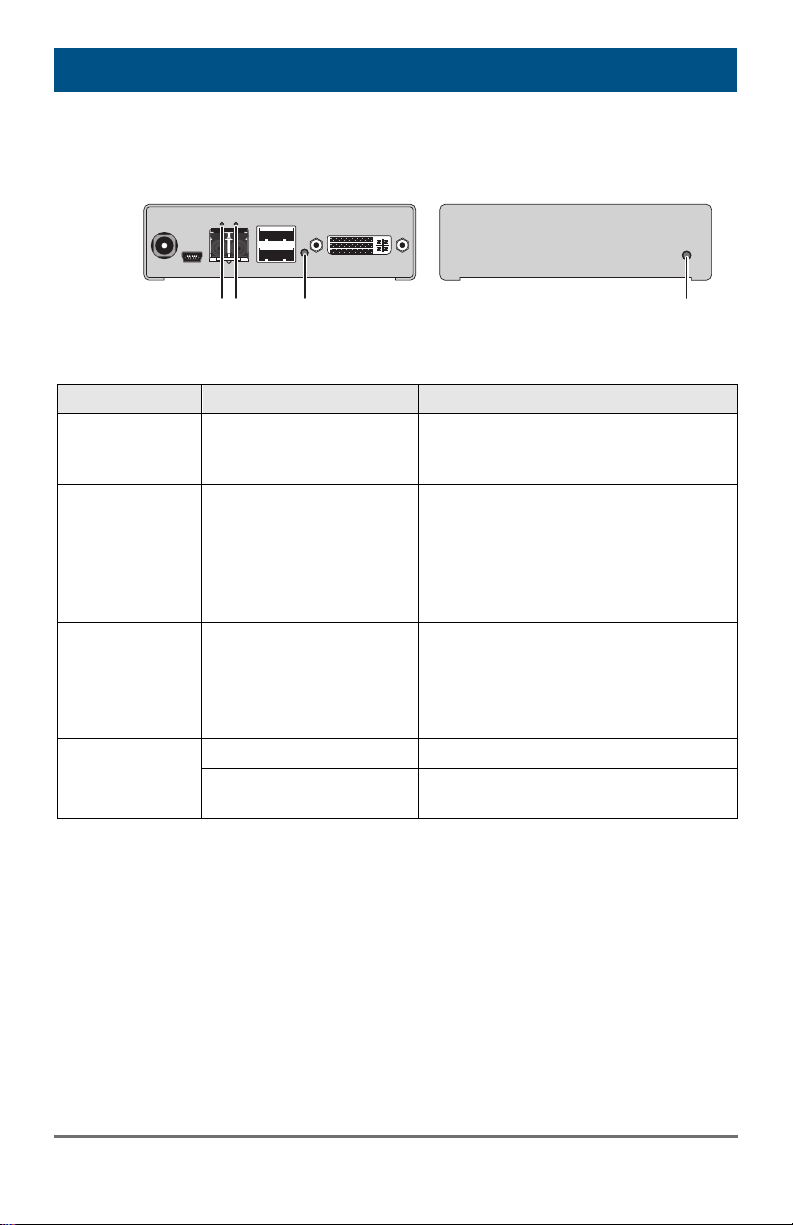
8.2 USB-HID
1
2
3
Rear View Front View
Diagnosis Possible Reason Measure
Keyboard LEDs
Shift and Scroll
Keyboard in Command
Mode
Press <Esc> to leave Command
Mode.
are blinking
CPU Unit:
LED 3 green or
violet
No USB connection to
CPU
Check connection of USB cable
to CPU; select another USB port
if necessary.
Remove USB and power cable
and restart CPU. Connect power
cable first.
CON Unit:
LED 3 green or
violet
Problems with USB
connection
Check connection of USB cable
to USB-HID device.
Remove DVI and power cable
and restart CON Unit. Connect
power cable first.
USB device
without function
No USB-HID device Connect USB-HID device.
USB-HID device is not
Contact dealer if necessary.
supported
Pos: 76 /806-IHSE/Hilfe im Problemfall/ Störung am seriellen Anschluss/477- xx_COMP @ 5\mod_12911295512 34_6.doc @ 45035 @ @ 1
3
32
2015-03-05
Page 33

Technical Support
9 Technical Support
Prior to contacting support please ensure you have read this manual, and
then installed and set-up your KVM Extender as recommended.
9.1 Support Checklist
To efficiently handle your request it is necessary to complete our checklist
for support and problem cases (Download). Keep the following information
available before you call:
Company, name, phone number and email
Type and serial number of the device (see bottom of device)
Date and number of sales receipt, name of dealer if necessary
Issue date of the existing manual
Nature, circumstances and duration of the problem
Involved components (such as graphic source/CPU, OS, graphic
card, monitor, USB-HID/USB 2.0 devices, interconnect cable)
including manufacturer and model number
Results from any testing you have done
9.2 Shipping Checklist
1. To return your device, contact your dealer to obtain a RMA number
2. Package your devices carefully, preferably using the original box.
3. Note your RMA number visibly on your shipment.
Devices that are sent in without a RMA number cannot be accepted. The
shipment will be sent back without being opened, postage unpaid.
Pos: 82 /806-IHSE/Zertifikate/UEB_Z ertifikate @ 5\mod_1278579534933_6. doc @ 42668 @ 1 @ 1
2015-03-05
(Return-Material-Authorization).
Add all pieces which you received originally.
33
Page 34
Draco KVM Extender
10 Certificates
Pos: 83 /806-IHSE/Zertifikate/ATB_Eur opäische Konformitätserklärung @ 5\ mod_1278579640901_6.doc @ 426 86 @ 2 @ 1
10.1 CE Declaration Of Conformity
The products listed below in the form as delivered comply with the
provisions of the following European Directives:
2004/108/EG Council Directive on the approximation of the laws of
the Member States relating to electromagnetic
compatibility
CE Marking
Product list:
Series 487
The products comply with the following harmonized standards for
Information Technology Equipment:
EN 55022:2010/AC:2011 (Class A)
EN 55024:2010 + A1:2001 + A2:2003
EN 61000-3-2:2006+A1:09+A2:09
EN 61000-3-3:2008
EN 61000-6-2:2005
This declaration certifies the conformity to the specified directives but
contains no assurance of properties. The safety instructions and
installation guidelines noted in this manual shall be considered in detail.
Compliance with the specifications for cable lengths and types is
mandatory.
Manufacturer:
IHSE GmbH
Maybachstrasse 11
88094 Oberteuringen
Deutschland
Use in a Domestic Environment
This is a Class A product. In a domestic environment, this product may
cause radio interference in which case the user may be required to take
adequate measures.
Oberteuringen, July 1st, 2014
The Management
34
2015-03-05
Page 35

Certificates
10.2 North American Regulatory Compliance
This equipment has been found to comply with the limits for a Class A
digital device, pursuant to Part 15 of the FCC Rules. These limits are
designed to provide reasonable protection against harmful interference
when the equipment is operated in a commercial environment. This
equipment generates, uses, and can radiate radio frequency energy and,
if not installed and used in accordance with the instruction manual, may
cause harmful interference to radio communications. Operation of this
equipment in a residential area is likely to cause harmful interference in
which case the user will be required to correct the interference at his own
expense.
Changes or modifications not expressly approved by the party responsible
for compliance could void the user’s authority to operate the equipment.
Shielded cables must be used with this equipment to maintain compliance
with radio frequency energy emission regulations and ensure a suitably
high level of immunity to electromagnetic disturbances.
All power supplies are certified to the relevant major international safety
standards.
Pos: 84 /806-IHSE/Zertifikate/ATB_W EEE @ 5\mod_1278579673292_6.d oc @ 42704 @ 2 @ 1
10.3 WEEE
The manufacturer complies with the EU Directive 2012/19/EU on the
prevention of waste electrical and electronic equipment (WEEE).
The device labels carry a respective marking.
Pos: 85 /806-IHSE/Zertifikate/ATB_R oHS @ 5\mod_1278579714214_6.doc @ 42722 @ 2 @ 1
10.4 RoHS/RoHS 2
This device complies with the Directive 2011/65/EU of the European
Parliament and of the council of 8 June 2011 on the restriction of the use
of certain hazardous substances in electrical and electronic equipment
(RoHS 2, RoHS II).
The device labels carry a respective marking.
10.5 Tempest
This device complies with the NATO directive SDIP-27 level B / zone 1
according to the NATO zone model.
2015-03-05
35
Page 36

Draco KVM Extender
The device labels carry a respective marking.
Pos: 86 /806-IHSE/Glossar/ATB_Glos sar @ 5\mod_1278576825433_6.doc @ 41890 @ 1 @ 1
36
2015-03-05
Page 37
Glossary
11 Glossary
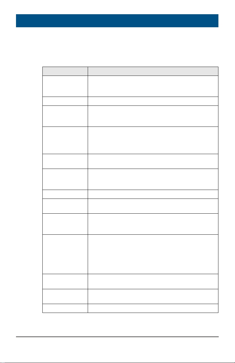
The following terms are commonly used in this guide or in video and KVM
technology:
Term Explanation
AES/EBU Digital audio standard that is officially known as
AES3 and that is used for carrying digital audio
signals between devices.
Cat X Any Cat 5e (Cat 6, Cat 7) cable
CGA The Color Graphics Adapter (CGA) is an old analog
graphic standard with up to 16 displayable colors and
a maximum resolution of 640x400 pixels.
Component
Video
Composite Video The Composite Video is also called CVBS and it is
CON Unit Component of a KVM Extender or Media Extender to
Console Keyboard, mouse and monitor
CPU Unit Component of a KVM Extender or Media Extender to
CVBS The analog color video baseband signal (CVBS) is
DDC The Display Data Channel (DDC) is a serial
Dual Access A system to operate a source (computer, CPU) from
Dual Link A DVI-D interface for resolutions up to 2560x2048 by
Dual-Head A system with two video connections
The Component Video (YPbPr) is a high-quality
video standard that consists of three independently
and separately transmittable video signals, the
luminance signal and two color difference signals.
part of the PAL TV standard.
connect to the console (monitor(s), keyboard and
mouse; optionally also with USB 2.0 devices)
connect to a source (computer, CPU)
also called Composite Video and it is part of the PAL
TV standard.
communication interface between monitor and
source (computer, CPU). It allows a data exchange
via monitor cable and an automatic installation and
configuration of a monitor driver by the operating
system.
two consoles
signal transmission of up to 330 MPixel/s (24-bit)
2015-03-05
37
Page 38
Draco KVM Extender
Term Explanation
DVI Digital video standard, introduced by the Digital
DVI-I A combined signal (digital and analog) that allows
EGA The Enhanced Graphics Adapter (EGA) is an old
Fiber Single-mode or multi-mode fiber cables
HDMI An interface for an all-digital transmission of audio
KVM Keyboard, video and mouse
Mini-XLR Industrial standard for electrical plug connections
Multi-mode 62.5µ multi-mode fiber cable or 50µ multi-mode fiber
OSD The On-Screen-Display is used to display information
Quad-Head A system with four video connections
RCA (Cinch) A not standardized plug connection for transmission
S/PDIF A digital audio interconnect that is used in consumer
SFP SFPs (Small Form Factor Pluggable) are pluggable
Single Link A DVI-D interface for resolutions up to 1920x1200 by
Single-Head A system with one video connection
Single-mode 9µ single-mode fiber cable
Display Working Group (http://www.ddwg.org). Single
Link and Dual Link standard are distinguished. The
signals have TMDS level.
running a VGA monitor at a DVI-I port – in contrast to
DVI-D (see DVI).
analog graphic standard, introduced by IBM in 1984.
A D-Sub 9 connector is used for connection.
and video data. It is differentiated between the HDMI
standards 1.0 to 1.4a.
The signals have TMDS level.
(3 pole) for the transmission of digital audio and
control signals
cable
or to operate a device.
of electrical audio and video signals, especially with
coaxial cables
audio equipment over relatively short distances.
interface modules for Gigabit connections. SFP
modules are available for Cat X and fiber
interconnect cables.
signal transmission of up to 165 MPixel/s (24-bit).
Alternative frequencies are Full HD (1080p), 2K HD
(2048x1080) and 2048x1152.
38
2015-03-05
Page 39
Glossary
Term Explanation
S-Video (Y/C) The S-Video (Y/C) is a video format transmitting
luminance and chrominance signals separately.
Thereby it has a higher quality standard than CVBS.
TOSLINK Standardized fiber connection system for digital
transmission of audio signals (F05 plug connection)
Triple-Head A system with three video connections
USB-HID USB-HID devices (Human Interface Device) allow for
data input.
There is no need for a special driver during
installation; "New USB-HID device found" is reported.
Typical HID devices include keyboards, mice,
graphics tablets and touch screens. Storage, video
and audio devices are not HID.
VGA Video Graphics Array (VGA) is a computer graphics
standard with a typical resolution of 640x480 pixels
and up to 262,144 colors. It can be seen as a
follower of the graphics standards MDA, CGA and
EGA.
=== Ende der Liste für Textmarke Inhalt == =
2015-03-05
39
 Loading...