

Page 1
SDMX PS/2 VGA- KVM-EXTENDER SDMX PS/2 VGA- KVM-EXTENDER SDMX PS/2 VGA- KVM-EXTENDER
Handbuch: http://www.ihse.de/pdf/b460-xx_e.pdf Handbuch: http://www.ihse.de/pdf/b460-xx_e.pdf Handbuch: http://www.ihse.de/pdf/b460-xx_e.pdf
1 Quick Setup
This section briefly describes how to install your KVM extender system. Unless you are an
experienced user, we recommend that you follow the full procedures described in the rest of this
manual. You can download the manual on:
http://www.ihse.de/pdf/b460-xx_e.pdf .
2 Installation
For first-time users, we recommend that you carry out a test placement, confined to a single room,
before commencing full installation. This will allow you to identify and solve any cabling problems,
and experiment with the SDMX KVM- extender system more conveniently.
2.1 Package Contents
You should receive the following items in your SDMX KVM- extender package:
• SDMX KVM-Extender- pair (Local Unit + Remote Unit)
• 1x 5V DC universal power supp ly for SDMX KVM- Extender (Remote Unit)
• 1x German type power cord
• 1x KVM CPU combination cable with PS/2 (6-pin MiniDIN male)
keyboard and mouse connectors, VGA video (HD15 male) connector, and
25-way (DB25 male) extender connector.
• 1x VGA video cable
• 1x audio cable (only devices with audio/serial option)
• 1x serial cable (only devices with audio/serial option)
• Quick Start Guide (Quick Setup).
If anything is missing, please contact Technical Support.
2.2 System Setup
To install your SDMX- Extender system:
1. Switch off all devices.
2. Connect your keyboard, monitor(s) and mouse to the Remote Unit (depending on device type).
Please ensure, to not swap Mouse- and Keyboard connector. The Keyboard connector is purple
and the Mouse connector is green.
3. Using the supplied CPU KVM cable(s), connect the keyboard, monitor(s) and mouse
connectors on the computer (or KVM switch). Please ensure, to not swap Mouse- and
Keyboard connector. The Keyboard connector is purple and the Mouse connector is green.
4. Connect the 5V power supply to power the Remote Unit. The Local Unit normally takes power
through the PCs keyboard port. In video only applications, this connection is not used and so an
external PSU is required. Please contact Technical Support to obtain a suitable power supply.
Only use the power supply originally supplied with this
equipment or a manufacturer-approved replacement.
5. If you have a dual access system, connect the keyboard, mouse and monitor for the Local
console to the appropriate ports on the Local unit. The ports may also be used to feed into a
KVM switch.
6. Connect the interconnect cable to the INTERCONNECT socket(s)
7. Power up the system.
2.3 Interconnection Cable Requirements
To connect SDMX KVM-Extender Local and Remote units you will need:
• VGA, PS2-K eyboard, PS2-Mouse: Connect the supplied VGA combination cable 1,8m
(VGA-Male, 2x PS2 Male on DB25 VGA/PS2-combination connector) with the CPU (KVMSwitch, etc.). Please ensure that the connection is tension-free!
• VGA: Connect the supplied V GA- cable 1,8m (VGA-Male to VGA-Male) with the CPU
(KVM.- Switch, etc.). Please ensure that the connection is tension-free!
• CATx cable: Recommended cable: S/UTP (Cat5) according EIA/TIA 56A, TSB 36 or Digital
STP 17-03170. Four pairs AWG 24. Wiring according EIA/TIA 568A (10BaseT). Use of
cables from a higher category (Cat5e, Cat6, Cat7) is possible.
The use of unshielded CATx- cable is possible; because of the higher electromagnetic
noise/sensitivity, the device class may not be reached. You may use flexible cables (patch
cable) type AWG26/8 but because of the higher loss of the stranded cables, the maximum
extension distance is reduced to approximately half the value of solid cables.
A point-to-point connection is required. You may use one or more patch panels in the
line. Do not connect the CATx- link interface (RJ45) to any other products, especially
telecommunications or network equipment like Hub, Switch, Router etc.
• Power Supply: Connect the supplied 5V/DC power supply to the Plug terminal on the Remote
Unit of your SDMX –KVM-Extender system.
Power Supply for ’VGA only’ application:
• Connect the optional power supply (434-2N) to the keyboard connector of the Local
Unit or
• Connect the optional USB to PS2 Adapter (434-UP) to the keyboard connector of
the Local Unit
• Serial cable: Connect th e supplied serial cable to your CPU/signal source.
• Audio cable: Connect the supp lied audio cable to your CPU.
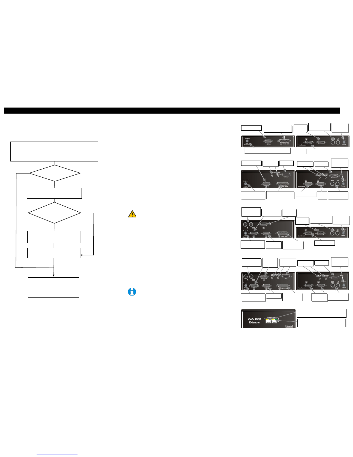
3 Device view (depending on device type)
SDMX KVM-Extender Type K460-SX Local and Remote Unit
SDMX KVM-Extender Type K460-SA Local and Remote Unit
SDMX KVM-Extender Type K460-DX Local and Remote Unit
SDMX KVM-Extender Type K460-DA Local and Remote Unit
SDMX KVM-Extender all types - Rear view of the Local and Remote Unit
Install system
1. Connect Remote unit to KVM and audio/serial devices (if present).
2. Connect Local unit to CPU or switch.
3. Connect Local and Remote units with matching interconnection cable
(CATx).
4. Power up the system.
Done
TFT Users: Set monitor to auto-adjust,
or if you are an advanced user,
manually adjust the monitor’s clock
and phase for optimum video quality.
Single
NO
Configure
single channel or
both?
YES
Interconnect cable
>25m?
Enter Command Mode on Remote unit
<Left Control> + <Left Shift> + <F10>
INTERCONNECT 2 – carries
secondary video signals.
INTERCONNECT 1 – carries
primary video and data signals.
Choose video channel: <1> or <2>
Adjustments apply to selected channel.
2nd VGA In
Serial
Out
Audio In/Out
2nd VGA In
1st VGA, Mouse/
Keyboard In
Serial Out
Audio In/Out
2nd VGA Out
1
st
VGA
Out
Mouse/ Keyboard
Out
VGA, Mouse/
Keyboard In
2nd VGA Out
2nd VGA
In
Mouse/Keyboard
Out Local
1st VGA
Out
2
nd
VGA Out
Mouse/Keyboard
Out Local
Serial Out
Audio In/Out
VGA Out
Local (VGA
st
nd
Audio In/Out
Serial In
BOTH
Set Video Equalization
<Left Control> + <E>
More channels?
YES
NO
Connect to 1st VGA,
Mouse/ Keyboard
2nd VGA Out
Connect to 5V power supply (at ’VGA only’)
VGA, Mouse/
Keyboard In
2nd VGA In VGA Out
(VGA 1+2nd)
Mouse/ Keyboard
Out
Connect to 5V
power supply
Connect to 5V
power supply
Connect to 5V power
supply (at ’VGA only’)
Mouse/ Keyboard
Out
Connect to 5V
power supply
1
st
VGA
Out
Connect to 5V power
supply (at ’VGA only’)
Connect to 5V power
supply (at ’VGA only’)
Mouse/ Keyboard
Out
Connect to 5V
power supply
1
st
VGA
Out
Page 2
SDMX PS/2 VGA- KVM-EXTENDER SDMX PS/2 VGA- KVM-EXTENDER SDMX PS/2 VGA- KVM-EXTENDER
Handbuch: http://www.ihse.de/pdf/b460-xx_e.pdf Handbuch: http://www.ihse.de/pdf/b460-xx_e.pdf Handbuch: http://www.ihse.de/pdf/b460-xx_e.pdf
3.1 Diagnostic LEDs
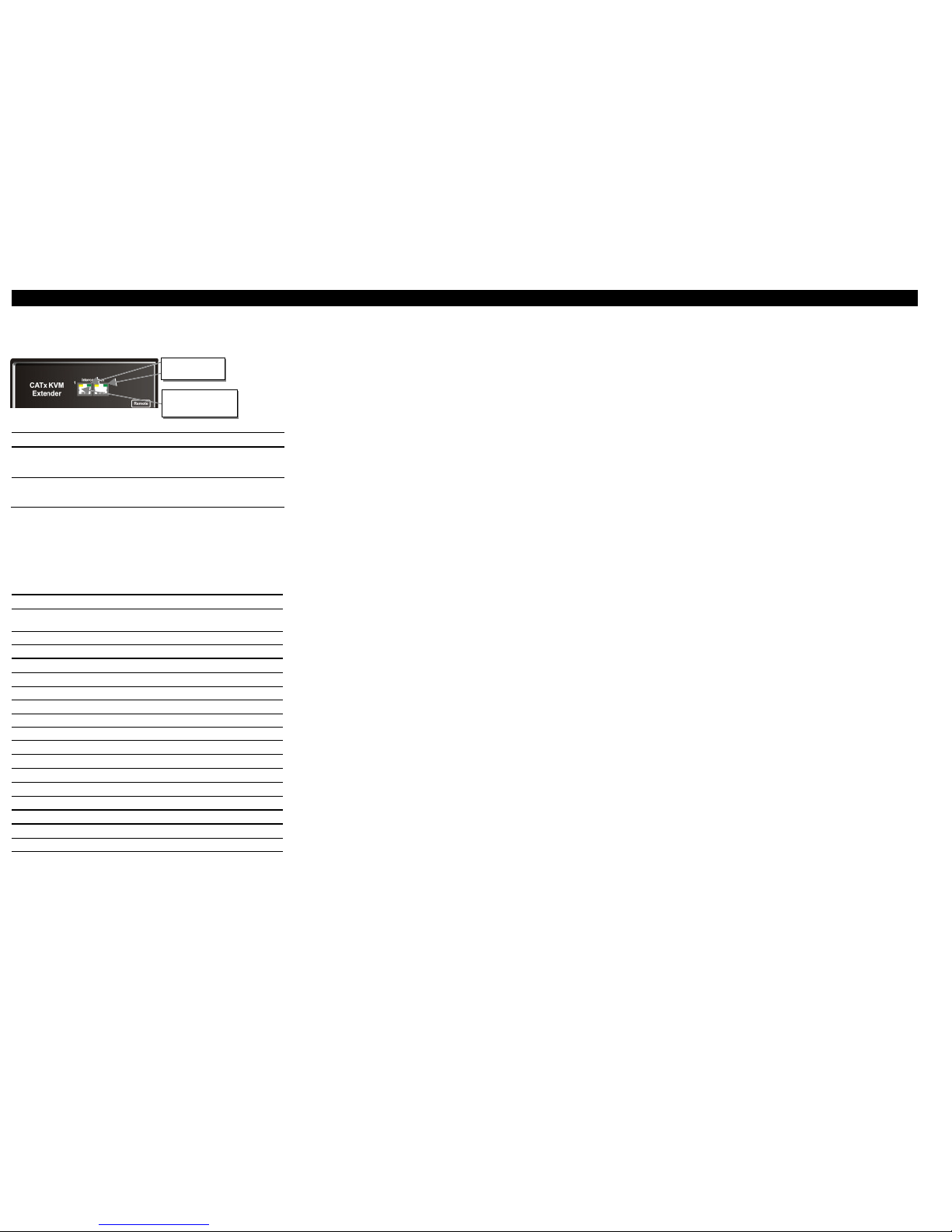
Each SDMX KVM-Extender is fitted with two indicator LEDs: Power and Link Status: The Power
and Link LEDs are at the upper CATx- connectors in the left and right upper corner at the Local and
Remote Unit. The location of the LEDs is shown below:
Status- LEDs at SDMX – KVM Extender
LED Zustand Bedeutung
Power LED
(Green LED)
Off
On
blinking
Device not powered, no video signal
Device powered correctly, no video signal
Device powered correctly, video signal OK
Link LED
(Yellow LED)
Off
blinking
No data transfer between Local and Remote Unit
Device ready
The yellow LED is only active on channel 1!
4 More Settings (summary of the most important
keys)
By executing a ‘hot-key-sequence', the Remote Unit is shifted into a Command Mode. Using this
Command Mode, you can configure the Extender for your needs. In the table below you can find
various keyboard commands:
Command Mode
Enter Command Mode*
<Left CRTL> + <Left Shift> +
<F10>
Exit Command Mode & Save*
<ESC>
Exit Command Mode Without Save*
<Left CRTL> + <ESC>
Video - Channel Selection, Equalization and DDC
Select Channel For Adjustment
<1>, <2>
Select BOTH Video Channels
<0>
Toggle Video Equalization
<Left CRTL> + <E>
Disable DDC Emulation
<Left CRTL> + <F2>
Enable DDC Emulation
<F2>
Transfer DDC from monitor to Local Unit
<Left CRTL> + <D>
Reset Commands
Reset Mouse and Keyboard*
<F1>
Mouse Recovery*
<F3>
Set Extender To Default State*
<Left CRTL> + <F9>
Private Mode
Toggle Private Mode*
<Scroll Lock>
Toggle Video Blanking State at other console*
<Left CRTL> + <Scroll Lock>
* Commands also available at Local console in Dual Access Kits: SDMX/D2 and
SDMX/DA2
5 Switch function (only K460-DX and K460-DA)
Both monitors show the current activity on the computer irrespective of which console is in use.
Any key press or mouse movement activates the respective console. When one console is in use, the
system blocks out the other console until there is no keyboard or mouse use at the active console for
two seconds.
Please note: using a normal mouse (with rolling ball), it may happen that the mouse lies
unfavourable, that slightest vibrations send constantly mouse movements to the computer. Thus is
no longer access from the other side possible. Please move your mouse a little bit, so that a stable
situation is reached. Or at extreme vibrations, please disconnect the mouse until you need this
workplace again.
5.1 Local Unit Commands:
All SDMX Local units with dual access and audio/ serial option accept commands entered at the
Local Unit. All SDMX Local units with dual access have also an 'enlarged Private Mode', where the
Local Unit can lock the Remote Unit and vice versa.
All commands consist of two key commands, to be actuated in succession (not simultaneously).
To enter a command, the Start button has to be actuated (by default it is the right <Ctrl> key)
followed by the command key. (The start button can be modified, see manual)
5.2 Toggle Private Mode <Scroll Lock>
Turns off the remote monitor and locks remote keyboard/ mouse. The Scroll Lock LED at the local
keyboard flashes slowly to indicate Private Mode. All three LED's at the remote keyboard are
illuminated to indicate Private Mode. Use this command again to cancel Private Mode.
6 Serial/Audio Interface – handling multiple devices
The serial interface transmits/receives six signals (3 signals in each direction). Normally four of
these signals are used for hardware handshaking (in addition to Tx & Rx). However, because each
handshaking line can support signals up to 19,200 Baud it is possible to configure the serial interface
to handle up to three simple 2-wire (Tx/Rx only) serial links. To do this you will need to construct a
custom breakout cable. Please contact technical support for further information. Select Xon/Xoff
software flow control on the printer and CPU.
6.1 Audio Interface
The audio interface is line-level and is designed to take the output from a sound card (or other linelevel) source and be connected to a set of powered speakers at the other end of the link. Stereo audio
may be transmitted either way across the link (simultaneously). No setup is required unless a
microphone is connected to the Remote Unit. Connect up as follows:
• Take the line-level output from your sound card (green conn ector) and connect to
‘Line In’ on the extender.
• A set of powered speakers may be con nected directly to ‘Line Out’ at the opposite end of
the link.
6.2 Using a microphone
A microphone may be plugged into the ‘Line In’ connector on the Remote Unit. There are two ways
of setting up a microphone:
• The Local Unit’s ‘Line Out’ connection should normally be wired to th e microphone input
(red) on your sound card. The sound card should then be set up to provide additional
amplification (+20dB). This is the preferred connection method.
• Alternatively, the Remote Unit itself can provide micropho ne amplification. To set this,
open up the Remote Unit and locate the jumper labelled ‘MIC’ on the daughterboard.
Connect this jumper across the pins. The Local Unit’s ‘Line Out’ connection should then
be wired to ‘Line In’ (blue) on your sound card.
If your microphone is already amplified, follow the second method but DO NOT install the
amplification jumper in the Remote Unit.
SDMX-PC
PS/2 VGA-KVM-Extender
Type:
K460-SX
K460-DX
K460-SA
K460-DA
(Quick Setup)
Diagnostic LED
Power
Diagnostic LED
Link Status
(only at channel1)
 Loading...