

Page 1
DVXI/LC-XM/-XS DVI- KVM-EXTENDER DVXI/LC-XM/-XS DVI- KVM-EXTENDER DVXI/LC-XM/-XS DVI- KVM-EXTENDER
manual: http://www.ihse.de/pdf/b456-xx_e.pdf manual: http://www.ihse.de/pdf/b456-xx_e.pdf manual: http://www.ihse.de/pdf/b456-xx_e.pdf
1 Quick Setup
This section briefly describes how to install your KVM extender system. Unless you are an
experienced user, we recommend that you follow the full procedures described in the rest of this
manual. You can download the manual on:
http://www.ihse.de/pdf/b456-xx_e.pdf.
2 Installation
For first-time users, we recommend that you carry out a test placement, confined to a single room,
before commencing full installation. This will allow you to identify and solve any cabling problems,
and experiment with the KVM extender system more conveniently.
2.1 Package Contents
You should receive the following items in your extender package (all types):
• DVXi/LC KVM-E xtender- pair (Local Unit + Remote Unit)
• 2x 5V DC universal power supp ly for the DVXi/LC - Extender
• 2x German type power cord
• User manual (Quick Setup)
K456-1W, K456-2W, K457-1W und K457-2W (additionally):
• DVI combi- connecting cable 1,8m (DVI-I male to DV I-I male, 2x PS2 male)
• PS2-keyboard-/ mouse adapter for the conn ection to the local Unit
K456-1U, K456-2U, K457-1U und K457-2U (additionally):
• DVI-I (1,8m) video cable (DVI-I dual l ink male-to-male)
• USB (1,8m) cable (USB type A to t ype B)
K456-2W, K456-2U, K457-2W K457-2U (additionally):
• DVI-I (1,8m) video cable (DVI-I dual l ink male-to-male)
If anything is missing, please contact our Technical Support.
2.2 System Setup
To install your DVXi/LC – Extender system:
1. Switch off all devices.
2. Connect your keyboard, monitor(s) and mouse to the Remote unit (depending on device type).
Please ensure, not to swap Mouse- and Keyboard connector. The Keyboard connector is purple
and the Mouse connector is green.
3. Using the supplied CPU KVM cable(s), connect the keyboard, monitor(s) and mouse
connectors on the computer (or KVM switch). Please ensure, not to swap Mouse- and
Keyboard connector. The Keyboard connector is purple and the Mouse connector is green.
4. Connect the 5V power supply to power the unit.
Only use the power supply originally supplied with this
equipment or a manufacturer-approved replacement.
5. For a dual access system, connect the keyboard, mouse and monitor for the Local console to the
appropriate ports on the Local unit. The ports may also be used to feed into a KVM switch. To
the local (PS2-) Keyboard-/ Mouse port you can attach a Keyboard directly or Mouse/
Keyboard together, using the delivered adapter.
6. Connect the interconnect cable (fibre cable) to the local and the remote unit.
7. Power up the system.
2.3 Interconnection Cable Requirements
To connect the Local and Remote units you will need:
• DVI, PS2-Keyboard, PS2-Mouse: Con nect the supplied KVM CPU cable set to your CPU
(KVM.- Switch, etc.). Please ensure that the connection is tension-free! Devices K456-1W,
K456-2W, K457-1W + K457-2W
• DVI, USB-Keyboard, USB-M ouse: Connect the supplied DVI-I cable (DVI-I to DVI-I) and
the USB-cable (USB-A to USB-B) to your CPU. Please ensure that the connection is tensionfree! Devices K456-1U, K456-2U, K457-1U + K457-2U
• DVI: Connect the suppli ed DVI CPU cable set to your CPU (KVM.- Switch, etc.). Please
ensure that the connection is tension-free! Devices K456-2W, K456-2U, K457-2W und K4572U
• Fibre Cables:
• Multi mode: Two fibers 50µm or 62.5µm. E.g. I-V(ZN)H 2G50 (In house patch
cable)or I-V(ZN)HH 2G62,5 (In house Breakout cable) or I/AD(ZN)H 4G50 (in
house OR outdoor Breakout cable, stress resistant) or A/DQ(ZN)B2Y 4G62,5
(outdoor cable, stress resistant with protection against animal biting) All notations
acc. VDE specification.
• Singlemode: Two fibers 9µm. E.g. I-V (ZN)H 2E9 (In house patch cable) or I-
V(ZN)HH 2E9 (In house Breakout cable) or I/AD(ZN)H 4E9 (in house OR outdoor
Breakout cable, stress resistant) or A/DQ(ZN)B2Y 4G9 (outdoor cable, stress
resistant with protection against animal biting) All notations acc. VDE specification.
A point to point connection is required. Having one or more patch panels in the
line is possible and allowed. Not allowed is a connection from the fibre lin k
interface to any other products, especially telecommunications or n etwork
equipment.
• Power Supply
Connect the supplied 5V/DC power supplies to the Plug terminal on the rear of both Local and
Remote units.
3 Device view (depending on device type)
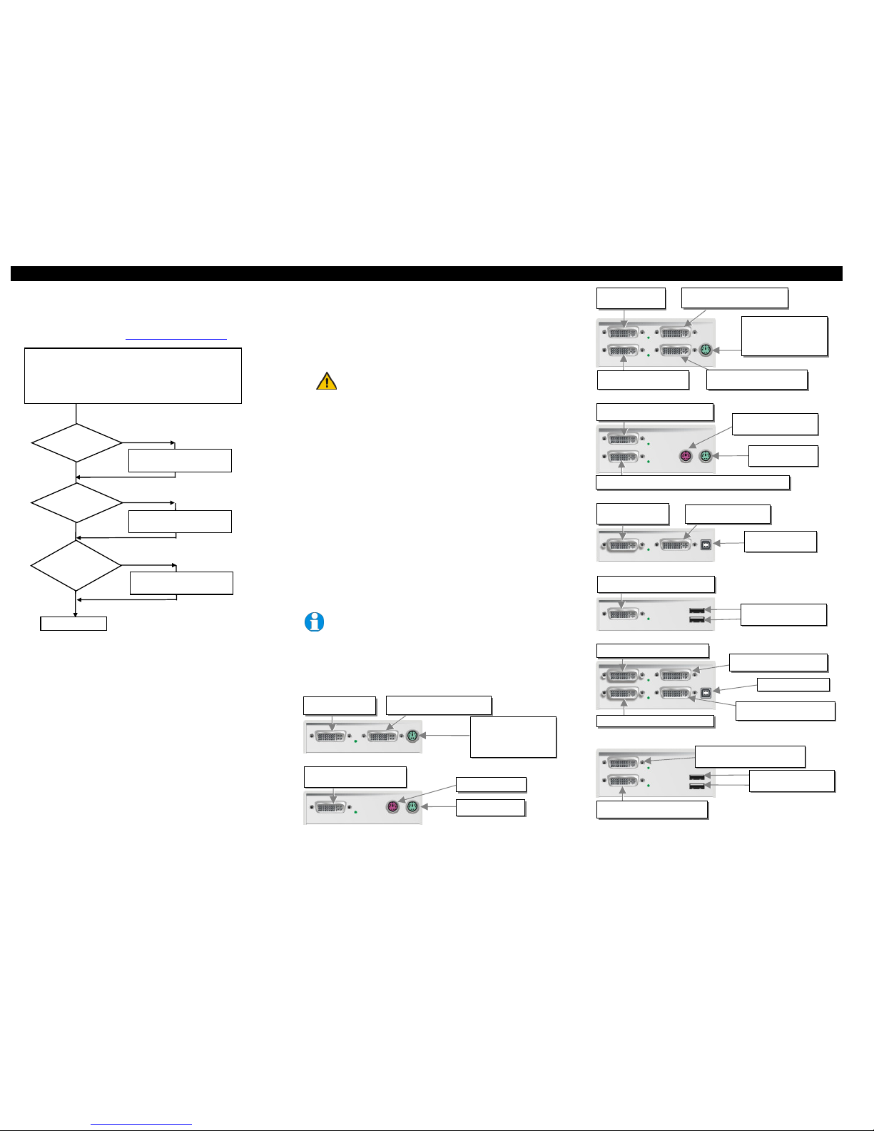
DVXi/LC KVM-Extender type K456-1W und K457-1W Local Unit
DVXi/LC KVM-Extender Typ K456-1W und K457-1W Remote Unit
DVXi/LC KVM-Extender Type K456-2W and k457-2W Local Unit
DVXi/LC KVM-Extender Type K456-2W und K457-2W Remote Unit
DVXi/LC KVM-Extender Type K456-1U / K457-1U Local Unit
DVXi/LC KVM-Extender Type K456-1U / K457-1U Remote Unit
DVXi/LC KVM-Extender Type K456-2U / K457-2U Local Unit
DVXi/LC KVM-Extender Type K456-2U / K457-2U Remote Unit
Remote DVI-Monitor port– connect to
Remote console monitor
Remote mouse port
Remote keyboard port
Connect to CPU:
2nd DVI-Graphic card
2nd local DVI-Monitor port Connect to
Local console 2nd monitor
Connect to CPU: 1st DVI-
Graphic card, keyboard, mouse
Local DVI-Monitor port Connect to
Local console monitor
Local keyboard/ mouse port
Solely Keyboard may be
plugged in directly,
keyboard/mouse through
equipped adapter
2nd remote DVI-Monitor port Connect to
Remote cons
ole 2nd monitor
1st remote DVI-Monitor port– connect to Remote console 1st monitor
Remote mouse port
Remote keyboard port
Connect to CPU:
DVI, keyboard, mouse
Local DVI-Monitor port Connect to
Local console monitor
Local keyboard/ mouse port
Solely Keyboard may be
plugged in directly,
keyboard/mouse through
equipped adapter
Install system
1. Connect Remote unit to KVM.
2. Connect Local unit to CPU or switch.
3. Connect Local and Remote units with matching interconnection cable
(fibre cables).
4. Power up the system.
Done
YES
NO
Link LED
illuminated ?
NO
NO
YES
Check p.s.u.’s and connection
to power outlet
Power LED
illuminated?
Check the fibre cable, and
fibre connectors
Check settings of graphic card
or boot CPU
Video OK
LED ?
illuminated ?
YES
Connect to CPU:
DVI graphic card
local DVI-Monitor port Connect
to Local console monitor
Connect to CPU:
USB
remote DVI-Monitor port– connect to
Remote console monitor
Remote keyboard/mouse
port
Local 1st DVI-Monitor port Connect
to Local console 1
st
monitor
Connect to CPU: USB
Connect to CPU: 2nd DVI-Graphic card
Connect t
o CPU: 1st DVI-Graphic card
2nd local DVI-Monitor port Connect
to Local console 2
nd
monitor
2nd remote DVI-Monitor port Connect to
Remote console 2nd monitor
1st remote DVI-Monitor port– connect to
Remote console 1st monitor
Remote keyboard/ mouse
port
Page 2
DVXI/LC-XM/-XS DVI- KVM-EXTENDER DVXI/LC-XM/-XS DVI- KVM-EXTENDER DVXI/LC-XM/-XS DVI- KVM-EXTENDER
manual: http://www.ihse.de/pdf/b456-xx_e.pdf manual: http://www.ihse.de/pdf/b456-xx_e.pdf manual: http://www.ihse.de/pdf/b456-xx_e.pdf
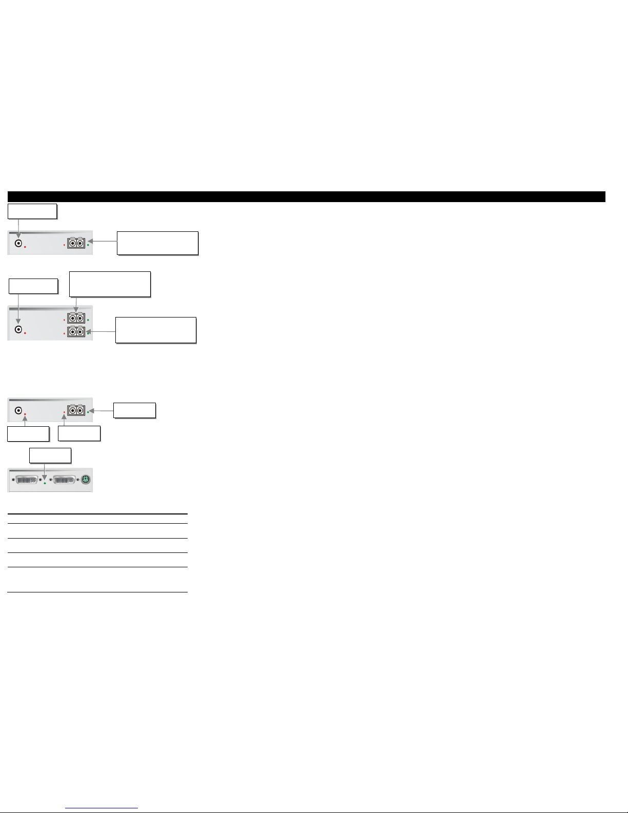
DVXi/LC KVM-Extender Type K456-1W, K456-1U, K457-1 W and K457-1U Local/
Remote Unit
DVXi/LC KVM-Extender Type K456-2W, K456-2U, K457-2 W and K457-2U Local/
Remote Unit
3.1 Diagnostic LEDs
Each DVXi/LC KVM-Extender is fitted with four indicator LEDs: Power, Video OK, Data Error,
Link Status: The Power LEDs are next to the Power socket.
The location of the LEDs is shown below:
Diagnostic - LEDs at DVXi/LC - Extender
LED Appearance Diagnostics
Power LED
(Red LED)
Off
On
Device not ready
Device ready
Video Okay
(Green LED)
Off
On
No or invalid video signal detected
Device ready
Link Status
(Green LED)
blinking
On
No CAT5 connection
Device ready
Data Error
(Red LED)
Off
blinking / On
Device ready
Errors through data transmission over fiber Cable
(Cable too long, too high attenuation or too much
EMI interferences )
4 Troubleshooting
Monitor
There isn’t a picture.
Check the power supply connection at the Local and Remote unit. Is the Power (Red
LED) at the Local and Remote unit illuminated? If not, the internal power-supply may be
damaged or there may be an internal error.
Check that the Interconnection cable is connected at the Local Unit and the Remote Unit.
Is the Link Status LED illuminated? If not, there may be a problem with the
Interconnection cable:
Are there Errors through data transmission over fibre Cable (Cable too long, too high
attenuation or too much EMI interferences )? Is the Data Error LED illuminated or
blinking? If yes, check cable length and environment.
Video Okay LED is dark: CPU does not provide a video signal – Check settings of the
graphic card. Try out, connecting a monitor to the local output, to see, whether there is a
signal or not.
Keyboard
The PC boots fine with no error messages but the keyboard does not work at all
Wrong cable plugged in, keyboard and mouse cables reversed.
Try a different model of keyboard. If the new keyboard works then original one may be
incompatible
Check that the Interconnection cable is connected at the Local Unit and the Remote Unit.
Is the Link Status LED illuminated?
The other console is active. Gain control by any keyboard action or by pressing left and
right mouse buttons simultaneously.
PS2-Mouse
A mouse cursor appears on the screen, but the mouse does not work
Wrong cable plugged in, keyboard and mouse cables reversed.
Try a different model of mouse
You have connected the Local unit while the CPU was running. Therefore you have
connected first the keyboard cable and then the mouse cable. Disconnect the keyboard
cable and connect it again. Please reboot you CPU if the mouse is still not running.
The system does not detect a PS/2 mouse, or the application cannot find the mouse.
Wrong cable plugged in, keyboard and mouse cables reversed.
Ensure that the Local Unit is connected to the PC keyboard port to provide power.
USB-Keyboard/USB-Mouse
Your USB-keyboard/USB-mouse does not work
Although we tried to design the devices as transparent as possible, we can’t ensure that all
devices are running. Please check in the manual the list of the tested devices.
USB-HID devices
Your USB-HID device does not work
Although our interface supports HID devices, we can’t ensure that every connected device
is running. In case of a malfunction please contact our technical support.
Other USB-devices
Your USB- device does not work
You have connected a non-HID device. There are supported HID devices only. All other
devices are dismissed
DVXi/LC-xM /-xS
DVI-KVM-Extender
Type:
K456-1W
K456-1U
K456-2W
K456-2U
K457-1W
K457-1U
K457-2W
K457-2U
(Quick Setup)
Connect to 5V Power
supply
Connect to 5V Power
supply
Diagnostic LED
Power
Diagnostic LED
Video OK
Diagnostic LED
Data Error
Diagnostic LED
Link Status
INTERCONNECT – carries video and
data signals – connect to Local/
remote unit with fiber cable
Fibre-Plug type: LC
INTERCONNECT – carries 2nd video
signal – connect to Local/ remote unit
with fiber cable
Fibre-Plug type: LC
INTERCONNECT – carries 1st video
and data signals – connect to Local/
remote unit with fiber cable
Fibre-Plug type: LC
 Loading...