

IHP Superior ERC4054, Superior ERC4060, Comfort Flame MPE54L, Comfort Flame MPE60L Installation And Operation Instructions Manual

Installation and Operation Instructions
Linear Electric Fireplaces
P/N 900264-00 Rev. NC 07/2014
C
P900264-00
INSTALLER: Leave this manual with the appliance.
CONSUMER: Retain this manual for future reference.
TO ASSURE PROPER ALIGNMENT, INSTALL THIS
FIREPLACE IN A SQUARE AND PLUMB CONDITION,
USING SHIMS AS NECESSARY AT SIDES.
Do not alter or modify this fireplace or its components under any circumstances. Any modification or alteration of the fireplace system, including but not limited to the fireplace and accessories, may void the warranty,
listings and approvals of this system and could result in an unsafe and potentially dangerous installation.
Exposed surfaces of the electronic fireplace adjascent to heaters and blowers may become hot. Care should
be taken to avoid contact with blower heat discharge outlets such as the one on the top of this fireplace.
®
US
Models
SuperiorTM
Models:
ERC4054
ERC4060
Installateur : Laissez cette notice avec l’appareil.
Consommateur : Conservez cette notice pour consultation ultérieure.
DO NOT STORE OR USE GASOLINE OR OTHER FLAMMABLE
VAPORS AND LIQUIDS IN THE VICINITY OF THIS OR ANY
OTHER APPLIANCE.
AstriaTM
Models:
Arcturus54
Arcturus60
Comfort FlameTM
Models:
MPE54L
MPE60L
WARNING
If the information in this manual is not followed exactly, an electrical shock or fire may result causing property
damage, personal injury or loss of life.
IMPORTANT
Before starting your fireplace installation, read this installation and operation manual very carefully to ensure
you understand it completely and in entirety. Failure to follow these instructions may result in a possible
electric shock, fire hazard and/or injury or property damage and will void the warranty.
CAUTION
Extreme caution is necessary when any heater is used by or near children or invalids and whenever the heater
is left operating and unattended.

INNOVATIVE HEARTH PRODUCTS • LINEAR ELECTRIC FIREPLACE • INSTALLATION INSTRUCTIONS
IMPORTANT SAFETY AND
WARNIING INFORMATION
READ THIS MANUAL IN ITS
ENTIRETY AND UNDERSTAND
THESE RULES TO FOLLOW FOR
SAFETY.
WARNING
If the information in this manual
is not followed exactly, an electrical shock or fire may result
causing property damage, personal injury or loss of life.
IMPORTANT
Before starting your fireplace
installation, read this installation and operation manual
very carefully to ensure you
understand it completely and in
entirety. Failure to follow these
instructions may result in a possible electric shock, fire hazard
and/or injury or property damage
and will void the warranty.
CAUTION
Extreme caution is necessary
when any heater is used by or
near children or invalids and
whenever the heater is left operating and unattended.
IMPORTANT
These fireplaces are designed
as supplemental heaters. Therefore, it is advisable to have an
alternate heat source when
installed in a dwelling.
IMPORTANT
Cold climate installation recommendation: when installing this
fireplace against a non-insulated
exterior wall or chase, it is
mandatory that the outer walls
be insulated to conform to applicable insulation codes.
WARNING
To prevent contact with sagging or loose insulation, the
appliance must not be installed
against vapor barriers or exposed
insulation. Localized overheating could occur and a fire could
result. Insulation and a vapor
barrier should be placed a
minimum of 2 inches from the
appliance.
TO PREVENT A POSSIBLE FIRE,
DO NOT BLOCK AIR INTAKES OR
EXHAUSTS IN ANY WAY. DO NOT
USE NEAR SOFT SURFACES, LIKE
A PILLOW, WHERE OPENINGS MAY
BECOME BLOCKED.
THIS APPLIANCE MAY BECOME HOT
WHEN IN USE. TO AVOID BURNS, DO
NOT LET BARE SKIN TOUCH HOT SURFACES. KEEP COMBUSTIBLE MATERIALS, SUCH AS FURNITURE, PILLOWS,
BEDDING, PAPERS, CLOTHES AND
CURTAINS AT LEAST 3 FEET (1 METER)
FROM THE FRONT OF THIS APPLIANCE.
UNDER NO CIRCUMSTANCES SHOULD
THIS FIREPLACE BE MODIFIED. PARTS
HAVING TO BE REMOVED FOR SERVICING MUST BE REPLACED PRIOR TO
OPERATING THE FIREPLACE AGAIN.
DO NOT USE THIS APPLIANCE OUTDOORS. DO NOT EXPOSE FIREPLACE
TO THE ELEMENTS (SUCH AS RAIN,
ETC.).
THIS APPLIANCE IS NOT INTENDED
FOR USE IN BATHROOMS, LAUNDRY
AREAS OR SIMILAR INDOOR LOCATIONS. NEVER LOCATE THIS APPLIANCE WHERE IT COULD FALL INTO
A BATHTUB OR OTHER WATER CONTAINER.
DO NOT RUN ELECTRICAL WIRING OR
POWER CORD UNDER CARPETING. OR
COVER WITH THROW RUGS, RUNNERS
OR SIMILAR MATERIALS.
FOR 120 VAC POWER CORD AVOID THE
USE OF AN EXTENSION CORD BECAUSE
THE EXTENSION CORD MAY OVERHEAT
AND CAUSE A RISK OF FIRE. HOWEVER, IF YOU HAVE TO USE AN EXTENSION CORD, THE CORD SHALL BE NO.
14 AWG MINIMUM SIZE AND RATED
NOT LESS THAN 1800 WATTS, 15
AMPS. THE EXTENSION CORD MUST
BE A THREE CONDUCTOR SHEATH
CABLE WITH GROUNDING TYPE PLUG
AND CORD CONNECTION.
THIS APPLIANCE HAS HOT AND ARCING
OR SPARKING PARTS INSIDE. DO NOT
USE IT IN AREAS WHERE GASOLINE,
PAINT OR FLAMMABLE LIQUIDS ARE
USED OR STORED.
THIS FIREPLACE SHOULD NOT BE USED
AS A DRYING RACK FOR CLOTHING, NOR
SHOULD CHRISTMAS STOCKINGS OR
OTHER DECORATIONS BE HUNG NEAR IT.
USE THIS APPLIANCE ONLY AS
DESCRIBED IN THIS MANUAL. ANY
OTHER USE IS NOT RECOMMENDED BY
THE MANUFACTURER AND MAY CAUSE
A FIRE, ELECTRIC SHOCK OR INJURY
TO PERSONS.
DO NOT OPERATE ANY HEATER WITH
DAMAGED WIRING OR CONNECTORS,
OR AFTER THE APPLIANCE MALFUNCTIONS, OR IF IT HAS BEEN DROPPED
OR DAMAGED IN ANY WAY.
ANY REPAIRS TO THIS FIREPLACE
SHOULD BE PERFORMED BY A QUALIFIED SERVICE TECHNICIAN.
2
NOTE: DIAGRAMS & ILLUSTRATIONS NOT TO SCALE.
IF APPLIANCE IS TO BE DISCONNECTED, TURN OFF CONTROLS FIRST.
DO NOT INSERT OR ALLOW FOREIGN
OBJECTS TO ENTER ANY VENTILATION
OR EXHAUST OPENING, AS THIS MAY
CAUSE AN ELECTRIC SHOCK, FIRE, OR
DAMAGE TO THE APPLIANCE.
SAVE THESE INSTRUCTIONS.
900264-00 Rev. NC 06/14

INNOVATIVE HEARTH PRODUCTS • LINEAR ELECTRIC FIREPLACE • INSTALLATION INSTRUCTIONS
In selecting this Innovative Hearth Products linear electric fireplace, you have chosen
the finest and most dependable fireplace found anywhere. A beautiful and prestigious
addition to the finest homes. Welcome to a Family of hundreds of thousands of satisfied IHP Fireplace Owners.
Please read and carefully follow all of the instructions found in this manual. Please
pay special attention to the safety instructions provided in this manual. The instructions included here will assure that you have many years of dependable and enjoyable
service from your IHP product.
TABLE OF CONTENTS
Important Safety Information ........... Page 2
Packaging List .................................. Page 3
Introduction ..................................... Page 3
General Information ......................... Page 3
Locating Fireplace ............................ Page 3
Tools/Supplies Required .................. Page 3
Framing Specifications ..................... Page 4
Fireplace Specifications .................... Page 4
Clearances ....................................... Page 5
Pre-installation ................................. Page 5
Installation Steps ............................. Page 5
Electrical Connections ...................... Page 6
Final Finishing .................................. Page 6
Break-In Period ................................ Page 6
On/Off Switch ................................... Page 6
Remote Control Operation ............... Page 7
Operation Modes .............................. Page 7
Maintenance ..................................... Page 8
54" Fireplace Specifications .............. Page 9
60" Fireplace Specifications .............. Page 10
Troubleshooting ............................... Page 11
Exploded Diagram Key ..................... Page 12
Available Replacement Parts ............ Page 12
Exploded Diagram ............................ Page 13
Electrical Diagram ............................ Page 14
Warranty .......................................... Page 15
PACKAGING LIST
This assembled Electric Room Heater is
packaged with:
• One accessory package located in the
firebox, containing;
1. One Installation and Operation Manual.
2. One Warranty Certificate (in manual)
3. One Remote Control.
INTRODUCTION
This Electric Fireplace is designed for
residential applications to be wall mounted
or framed in as a fireplace.
This appliance has been tested in accordance with UL 2021 and CSA C22.2 No.
46-M198 standards for fixed and location
dedicated electric room heaters.
GENERAL INFORMATION
Power Supply Wire Specifications
120 Volt, 60 Hz, 1500 Watts:
Power is supplied to the fireplace through a
120Volt, 60Hz receptacle located withing reach
of the powercord provided with the fireplace.
If the heater option it to be used we suggest
that a separate circuit with breaker be used.
See Table 1.
TOOLS AND BUILDING SUPPLIES
NORMALLY REQUIRED
TOOLS:
Phillips Screwdriver
Hammer
Saw And/or Saber Saw
Level
Measuring Tape
Plumb Line
Electric Drill And Bits
Pliers
Square
Gloves
BUILDING SUPPLIES:
Framing Materials
Wall Finishing Materials
IMPORTANT NOTE: This fireplace system
is not difficult to install. However, in the
interest of safety, it is recommended that
the installer be a qualified or certified
“tradesman” familiar with commonly
accepted fireplace installation and safety
techniques as well as prevailing local
codes.
Power Supply Wire Gage
Voltage Wire Gage Fuse
120 V 14 GA. 15 AMP
Table 1
LOCATING YOUR PRO SERIES ELECTRIC
FIREPLACE
Your new fireplace may be mounted on or
recessed into a wall (see Figure 1).
When choosing a location for your new fireplace, ensure that the general instructions are
followed. Also, for the best effect, install the
fireplace out of direct sunlight and away from
overhead lighting. See Figure 1.
Top View Showing Approved
Room Locations of Fireplace
fireplace shown in gray.
Figure 1
Installation must conform to local codes.
In the absence of local codes, electrical
wiring and grounding must comply with
the National Electrical Code ANSI/ NFPA
70 - latest edition. In Canada, the current CSA C22-1 Canadian Electrical Code
- latest edition.
3
900264-00 Rev. NC 06/14
NOTE: DIAGRAMS & ILLUSTRATIONS NOT TO SCALE.
3

INNOVATIVE HEARTH PRODUCTS • LINEAR ELECTRIC FIREPLACE • INSTALLATION INSTRUCTIONS
Framing Dimensions for Recess Installation
A
B
C
WALL MOUNTED AND RECESSED INSTALLATION
The Electric Fireplaces listed in this manual accept either wall-mounted installation or can be installed as a recessed appliance
for a more finished appearance.
WALL MOUNTING OPTION
Surface wall mounting can be achieved by securing
the provided brackets to a surface such as a wall in
standard construction after first finding weightbearing studs.
If this option is used, you will be able to enjoy the full
functionality of the fireplace, including light and heat.
NOTE: Minimum distances between walls, floors, and
ceilings must be observed. See Figure 2. Failure to do
so may result in damage to finishing materials on the
wall including but not limited to paint and wallpaper.
RECESSED FRAMING OPTION
These Electric Fireplaces offer a recessed instalation (see Figure 3) that gives the fireplace a more
distinguished appearance.
Figure 2
Minimum distance from
ceiling 15 3/4” (600mm)
Minimum distance to
walls and floors 7 7/8”
(300mm)
Blower Heat
Discharge
Outlet
Recessed framing places the front glass on the unit
nearly flush with the wall. With this option, the fire-
Possible locations for
Electrical Receptacle/Outlet
place will be more permanently affixed in its desired
position in the home for a more dramatic presentation.
With recessed installation, the heater in the unit
must be disabled by removing the access panel
and pulling apart a pair of wires to the blower
(see Figure 6). In addition, the power switch must
be enabled and power will be controlled with the
provided remote.
Recessed Framing Dimensions
MODEL A - Height B - Width C - Depth
54"
60"
18 5/8" (473mm) 52" (1321mm) 4 1/8" (105mm)
18 5/8" (473mm) 52" (1321mm) 4 1/8" (105mm)
Figure 3: Recessed Framing Dimensions
4
NOTE: DIAGRAMS & ILLUSTRATIONS NOT TO SCALE.
900264-00 Rev. NC 06/14

INNOVATIVE HEARTH PRODUCTS • LINEAR ELECTRIC FIREPLACE • INSTALLATION INSTRUCTIONS
WARNING
Do not use this fireplace if any
part of it has been underwater.
Immediately call a qualified
service technician to inspect the
fireplace and replace any part of
the electrical system which has
been under water.
WARNING
The minimum recommended
safe distance from the fireplace
to adjacent walls and furnishings
is 15 3/4" (600mm).
FIREPLACE SPECIFICATIONS
54" Models: ERC4054, Arturcus54, and
MPE54L
Description: 54" Linear Electric Fireplace
Shipping Weight: 70 1/2 lbs. (32 KG)
Packaging:
57” x 6 1/2” x 22 3/8”
(1448mm x 165mm x 568mm)
4.94 cu. ft.
Power Requirements:
(120 Volt, 60 Hz.)
Rated Wattage - 1600 Watts
Amperage - 13.33 Amps
Blower CFM: 83 CFM
(120 V): 5,461 BTU/HR
60" Models: ERC4060, Arturcus60, and
MPE60L
Description: 60" Linear Electric Fireplace
Shipping Weight: 72 3/4 lbs. (33 KG)
Packaging:
62 3/8” x 6 1/2” x 22 3/8”
(1584mm x 165mm x 568mm)
5.3 cu. ft.
Power Requirements:
(120 Volt, 60 Hz.)
Rated Wattage - 1600 Watts
Amperage - 13.33 Amps
Blower CFM: 83 CFM
(120 V): 5,461 BTU/HR
MINIMUM CLEARANCES TO COMBUSTIBLES
This appliance is an electric fireplace designed
to be framed in with combustible materials (up
to the edge of the appliance).
Fireplace Clearances
WALL RECESS
Sides 7 7/8"
(300mm)
Floor 7 7/8"
(300mm)
Top 15 3/4"
(600mm)
Rear 0" (0mm) 0" (0mm)
Table 2
Mantel Clearance: Combustible and Noncombustible mantels may be installed above
the top of the face of fireplace.
When surface mounting the fireplace with
the heater function enabled, a shelf must be
a minimum of 15 3/4" above the discharge of
the heater.
0" (0mm)
0" (0mm)
0" (0mm)
PRE-INSTALLATION
Before You Start
Check appliance for any concealed damage.
DETAILED INSTALLATION STEPS
WALL MOUNTING
1. Do not connect the appliance until properly
fixed to the wall and the instruction manual
is read fully.
2. Two people are recommended for installation
of this electric fireplace heater.
3. Peel off the removable label and the protective sheet attached to the front tempered
glass.
4. To place the decorative crystals media
follow the steps as given below
a. To place the crystals, the front glass is
required to be removed from the heater panel
body. Unscrew top and side screws which
hold the glass as shown in Figure 4a and 4b.
Figure 4b
b. Once the screws are out the top metal
bracket will come loose, place the bracket
away. Make sure the glass is supported
while doing this. Lift the glass up and out
from the heater body.
c. Place the crystals along the light unit in
desired position.
d. Put the front glass back and place the
metal bracket on top of the glass so that
the bracket secures it. Put the fasten screws
back. Make sure the screws are tight and
the glass is secured before continuing with
the installation.
5. A minimum recommended viewing distance
of 15" is recomended.
6. For installation of the appliance, care must
be taken not to damage concealed cables.
Please be careful while drilling the holes.
7. This appliance is designed to be permanently
fixed to a wall at a minimum height of 7 7/8"
(300mm). The wall bracket must be
fitted horizontally and the cable routed to
the bot tom right of the heater.
8. A minimum height of 15" from bottom of
heater to floor is recommended for optimum
viewing of fuel bed. See the Figure 2 for the
recommended framing dimensions.
10. Carefully lift the heater up ensuring that
the top rear edge of heater engages the wall
bracket and is sit ting centrally. Two people
will make this operation easier.
11. Gently bring the heater level with the wall
and hang the heater to the heater bracket.
Ensure the heater body is locked in with the
wall bracket.
12. Attach the bottom bracket to the heater
panel body and mark the mounting hole;
remove the heater.
13. Drill the bracket mounting hole and fit the
wall plug.
14. Refit the heater to the wall and secure the
bottom bracket using the screws provided
to permanently fix the heater in place.
Ensure the heater body is engaged with the
wall bracket at the top. The heater is now
ready for use.
900264-00 Rev. NC 06/14
Figure 4a
NOTE: DIAGRAMS & ILLUSTRATIONS NOT TO SCALE.
5

INNOVATIVE HEARTH PRODUCTS • LINEAR ELECTRIC FIREPLACE • INSTALLATION INSTRUCTIONS
4 5/16”
1”
Fireplace
WARNING
Electrical wiring must comply
with local building codes and
other applicable regulations to
reduce the risk of fire, electrical
shock and injury to individuals.
IMPORTANT
Any electrical re-wiring of this
appliance must be done by a
qualified electrician.
ELECTRICAL CONNECTIONS FOR
RECESSED FRAMING OPTION
1. Complete the framing opening to the dimensions specified in Figure 3. Disable the
blower as shown in Figure 5. Insure that the
fireplace is in the off position (see Figures
7 and 8).
2. Wire a dedicated, properly fused circuit with
an Amp rating for the appropriate voltage
(120 V - 15 Amps). A dedicated circuit is
required to prevent overloading a house
circuit in cases of having multiple appliances
on the same circuit. Use an outlet that is
protected by a ground fault circuit interrupter
where required by electrical code.
3. Prepare the connections to power receptical:
120 Volt Connections - Locate the power
cord on the right side of the unit and connect
it to the outlet installed during the framing
(see Figure 5). Verify that the power to the
receptacle is off.
Hard wired installation:
Ensure that there is a minimum of 8" of the
service cable for connection to the junction
box on the fireplace.
- Loosen four screws to remove the junction
box cover plate.
- Disconnect and remove the 120 Volt power
cord from the fireplace wires.
- Position the fireplace into the framed-in
opening. Attach fireplace to frame using
nailing flanges provided.
- Complete the wiring to the fireplace as
shown on Page 14.
4. Perform a function test. See Fireplace Heater
On/Off on Page 7 and Remote Control
Operation on Page 8.
5. Turn the master power switch to the "Off"
position and cut the power to the breaker
leading to the appliance.
RECESSED INSTALLATION
OPTION
Use the following detailed instructions for
recessed installation.
Installing the fireplace is a two person job.
1. Prepare the wall recess and electrical
receptacle as see in Figure 3, Page 4. It may
be necessary to shem the wall bracket to the
wall forming the rear of the recess to meet
the minimum distance from the bracket to the
appliance (see Figure 7).
2. IMPORTANT: Cut off the breaker leading to
the appliance.
3. Follow the wiring details located in Figure
11 on Page 14.
3. Follow steps 1-5 found under WALL MOUNTING (see Page 5). to prepare decorative elements of the fireplace for installation.
4. Install the mounting bracket on the inside
wall or on the shem.
5. Disable the blower motor and heater by
removing the four screws in the Heater Cutoff
Access Panel and unplugging the wires as
seen in Figure 5.
Figure 5
6. Filp the master power switch to the "ON"
position.
7. Carefully seat the fireplace into the recess
opening near the top of the opening and lower
the appliance so that the mounting brackets
will catch against the brackets at the back of
the fireplace.
8. Turn the breaker supporting the fireplace
back on.
9. Use the supplied remote control to operate
the fireplace. For more information on fireplace
operation, see Page 8.
Figure 6
Recommended
Back of
recessed
wall
Mounting
bracket
appliance depth
in wall
4 5/16"
(110mm)
1" (25mm)
4 1/8"
(105mm)
Maximum recess depth
Front of
finished
wall
Glass
overlap
Fireplace
When the fireplace is fully installed
using the recess option, the viewing
glass should overlap the top opening
framing approximately 1" (25mm) and
extend to conceal the framing. See
Figure 6 above.
BREAK-IN PERIOD:
During the first few initial uses of this heater,
there may be a release of a slight, harmless odor.
This odor is a normal occurrence caused by the
initial heating of the internal heating elements
and should not reoccur.
6
NOTE: DIAGRAMS & ILLUSTRATIONS NOT TO SCALE.
900264-00 Rev. NC 06/14

INNOVATIVE HEARTH PRODUCTS • LINEAR ELECTRIC FIREPLACE • INSTALLATION INSTRUCTIONS
Note: Ensure the circuit breakers for the power
supply are turned on.
This appliance can be activated using the fireplace and heater On/Off Switch (see Figures 7
& 8) or by using the remote control when the
unit power switch is already in the "ON" position.
The manual controls are located on the firebox
floor on the front left (see Figure 5). If an
optional glass enclosure is installed, it must
be removed to access.
Fireplace and Heater On/Off
When the main power switch is turned on,
power is supplied to the fireplace.
On
Off
Figure 7
The On/Off Switch is located on the right
side of the unit below the Heater Cutoff
Access Panel. In the recessed install
option, this switch must be turned into
the "ON" position and the appliance
must be controlled with the remote
provided.
CAUTION
Disconnect power before
attempting any maintenance or
cleaning to reduce the risk of
fire, electrical shock or personal
injury.
WARNING
When cleaning the fireplace, the
fireplace must be cool.
CLEANING THE GLASS ENCLOSURE
PANEL
Over time the front glass panel may become
dirty or dusty. Dust can be removed by lightly
rubbing the glass surface with a clean, lint free
cloth or paper towel. To remove fingerprints
or other marks, use a damp cloth with a good
quality household glass cleaner. The front glass
panel should be completely dried with a clean,
lint free cloth or paper towel.
CAUTION
Do not use abrasive cleaners on
the glass panel. Do not spray
liquids directly onto any surface
of the fireplace.
OPERATION
The appliance can be turned on either by the
switch located on the lower right hand side of
the heater body or by supplied remote control.
Manual Operation
1. The main power ON/OFF switch in position
“O,” the heater is OFF.
2. When main power ON/OFF switch is at position “I,” the heater is ready to use.
3. Press the HEAT button on the remote control
repeatedly to set the heater to desired heat
setting.
4. Press the Flame brightness adjustment
button to adjust the flame height and ember bed
brightness. Press and release the FLAME control
button to cycle through LO, MED, HI and OFF.
SAFETY CUT-OFF
• This appliance is tted with a safety
cut-off which will operate if the heater
overheats (eg. due to blocked air
vents). For safety reasons, the heater
will NOT automatically reset.
• To reset the appliance, disconnect
the appliance from the mains supply
for at least 30 minutes. Reconnect
the supply to the main switch on the
appliance.
AUTO MODE
Figure 8
Main Power Switch in "OFF"
Position.
MAINTENANCE
This appliance has been designed to provide
many years of trouble-free service. The components that will need to be serviced have been
kept to a minimum. Periodic dusting of the
fireplace is all that should be required.
CAUTION
Handle glass very carefully to
prevent accidental breakage.
WARNING
An authorized service representative should perform any other
servicing.
Under this mode the heater will automatically
turn ON at high heat setting 1500w heat output
when the room temperature drops below 72˚F
(22˚ C). When the room temperature is between
72-77˚F (22-25˚ C) the heater output will switch
to low heat set ting 1000W. When the room
temperature goes above 77˚F (25˚ C) the heater
will be turned off and the cycle will continue.
900264-00 Rev. NC 06/14
NOTE: DIAGRAMS & ILLUSTRATIONS NOT TO SCALE.
7

INNOVATIVE HEARTH PRODUCTS • LINEAR ELECTRIC FIREPLACE • INSTALLATION INSTRUCTIONS
REMOTE CONTROL OPERATION:
REMOTE CONTROL
A
D
F
G
POWER
ON/OFF
FLAME
-5 OFF
AMBER
HEATER
TEMP. CONTROL
HIGH
LOW
ON/OFF
+5 MAX
ON/OFF
ROOM
B
C
E
I
H
-5 OFF
J
• When using the remote control, the power
on/off switch on the lower right side of the
unit must be in the "ON" position.
Figure 9
REMOTE CONTROL MODEL NO. R-37
PART NO. F2052
+5 MAX
BLUE
K
CAUTIONS
• Do Not Use Old Batteries With
New Ones.
• Do Not Use Batteries Other Than
The Type Specified (2 Ea. AA).
• Ensure Batteries Are Correctly
Installed In Remote Control.
Theis IHP Electric Fireplace is provided
with an Infrared light Remote Control.
All functions of the fireplace can be controlled through the remote control. Note:
The Effective range of the remote control
is up to approximately 26 feet (8 meters).
The functions identified on the remote (see
Figure 9) are as follows:
A. POWER BUTTON
Press once to turn on power to fireplace.
B. INDICATING LIGHT
Illuminates when signal is sent.
C. FLAME BUTTON
On/off switch for flame and ember light.
D. AMBER FLAME BUTTON (DIM)
Reduces brightness of amber light.
E. AMBER FLAME BUTTON (BRIGHTEN)
Increases brightness of amber light.
F. HEATER ON/OFF
This button will turn the heater ON and OFF
independent of the main button.
G. TEMPERATURE ADJUSTMENT BUTTON
(HIGH)
Highest heat output, up to 75° F.
H. TEMPERATURE ADJUSTMENT BUTTON
(LOW.)
Low heat output, up to 72° F.
I. TEMPERATURE ADJUSTMENT BUTTON
(ROOM)
Sets the fireplace to Auto Mode (See Opera-
tions)
J. BLUE FLAME BUTTON (LOWER)
Reduces brightness of blue light.
K. BLUE FLAME BUTTON (HIGHER)
Increases brightness of blue light.
REMOTE CONTROL OPERATION STEPS:
1. For remote to function make sure the heater
is plugged-in and main power switch located
on the bottom right hand side is in the “ON”
position.
2. When operating the remote make sure you
point the remote to the center of the heater unit
and make sure each time you press the button
the LED indicator located on top right hand
corner of the remote blinks. The buzzer inside
the unit will beep once; if the LED fails to blink
check the batteries. It takes some time for the
receiver to respond to the transmit ter. Do not
PRESS the buttons more than once within two
seconds for correct operation
3. Power On power button: The power-on button
at top left corner of the remote is the main ON/
OFF power button. This will turn off all the functions and the heater will be in standby mode.
4. Flame Power On button: This button controls
both the amber and blue color flame. Press this
button once to turn ON the flame effect. Once the
flame effect is ON use the + and – but tons as
explained below to adjust the flame brightness
as desired. Press this button again to turn OFF
the flame effect. The heater can function even
when the flame effect is turned off if so desired.
The Red Flame +5 or -5 buttons control the
brightness of the Amber fame. To increase the
brightness/flame height, press and release the
flame +5 button. Each time you press this button
the brightness will increase by a small amount,
until the maximum is reached.
Press and release the Red Flame -5 button. Each
time you press this button the brightness will
decrease by small amount, until the minimum
brightness is reached.
The Blue Flame +5 or -5 buttons control the
brightness of the Blue fame. To increase the
brightness/flame height, press and release the
Blue Flame +5 button. Each time you press this
button the brightness will increase by a small
amount, until the maximum is reached.
To decrease the brightness / flame height, press
and release the Blue Flame -5 button. Each
time you press this but ton the brightness will
decrease by small amount, until the minimum
brightness is reached.
Using these settings you can mix the amber and
the blue flame to create a realistic or stylized
flame effect. Color mixes will also be reflected
in the crystal ember bed for added impact.
5. Heater Power Button: This button is the
heater ON/OFF button. Press this button to turn
the heater ON. The heater will always turn on at
the highest setting. In order to reduce the temperature on the heater press this button again.
High Button: Press the high button to switch the
heater directly to high heat setting of 1500W.
Low Button: Press the high button to switch
the heater directly to low heat setting of 750W.
Room Temp Button: Press the high but ton to
switch the heater to AUTO Mode (See Operations, Page 7).
6. To turn OFF the heater unit completely press the Power Button once.
8
NOTE: DIAGRAMS & ILLUSTRATIONS NOT TO SCALE.
8
900264-00 Rev. NC 06/14

INNOVATIVE HEARTH PRODUCTS • LINEAR ELECTRIC FIREPLACE • INSTALLATION INSTRUCTIONS
54” (1372mm)
4 3/4” (120mm)
20” (508mm)
54” (1372mm)
20” (508mm)
4 3/4” (120mm)
22 7/16” (596mm)
4 3/4” (120mm)
20” (508mm)
54” (1372mm)
54" LINEAR ELECTRIC FIREPLACE
54” (1372mm)
20” (508mm)
22 7/16” (596mm)
900264-00 Rev. NC 06/14
NOTE: DIAGRAMS & ILLUSTRATIONS NOT TO SCALE.
9
2” (50mm)
54” (1372mm)
20” (508mm)
1/16”
(19
)
53”
(134
)
60”
(1
24
)
1/16”
(19
)
53”
(134
)
60”
(1
5
24
mm
)
4” (102mm)
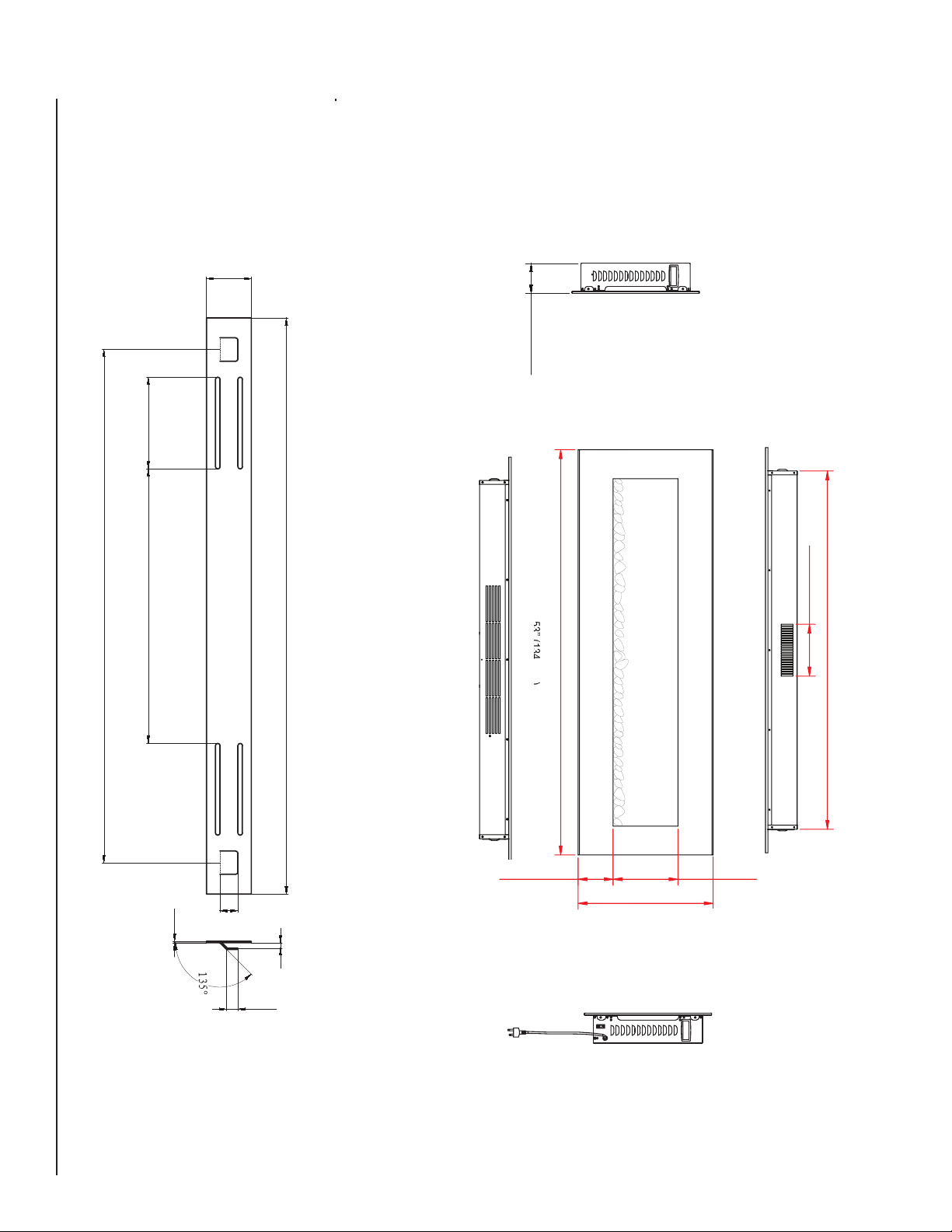
INNOVATIVE HEARTH PRODUCTS • LINEAR ELECTRIC FIREPLACE • INSTALLATION INSTRUCTIONS
MOUNTING BRACKET
4 3/4” (120mm)
60" LINEAR ELECTRIC FIREPLACE
22 1/2” (569 mm)
12” (305mm)
1.5mm
25” (639mm)
>1” (20mm)
6mm
7
5mm
7mm
5 3/16” (132mm)
5
mm
7
5mm
7mm
9 5/8” (244mm)
20” (436mm)
10
12.4 mm
NOTE: DIAGRAMS & ILLUSTRATIONS NOT TO SCALE.
900264-00 Rev. NC 06/14

TROUBLESHOOTING
INNOVATIVE HEARTH PRODUCTS • LINEAR ELECTRIC FIREPLACE • INSTALLATION INSTRUCTIONS
Symptom Possible Causes Who Performs Corrective
Corrective Action
Action
1. Fireplace does not turn on when
the power button on the remote is
pushed.
2. Fireplace does not turn on when
main power switch is engaged.
3. Flame is fixed (unmoving). Wiring may be loose or the flame
4. Dim or poorly visible flame or LED
ember bed is not glowing.
5. Flame sputters. Flame motor is defective. Qualified service technician Replace flame motor.
6. Remote control does not work. Low batteries.Unit switch and/or
7. Circuit breaker trips or fuse blows
when the unit is turned on.
Main power switch on the lower
right side of the fireplace is in the
off position.
Appliance is not plugged in or there
is no power to the receptacle
motor may be defective.
LED strip failure or wiring is loose. Qualified service technician Inspect all wiring for loose connec-
wall switch in “on” position.
Improper circuit current rating. Qualified service technician Check the house circuit to ensure it is
Homeowner Turn on the main power switch.
Homeowner Plug unit in or confirm that the circuit
breaker is switched on.
Qualified service technician Inspect all wiring for loose connec-
tions. If the wire connections are good,
replace the flame motor.
tions and repair or replace if necessary. Inspect LED strips and replace
if necessary.
Homeowner Replace aa batteries in remote control.
If problem persists, there may have
been a loss of power to the unit as a
possible result from a power failure
(i.E. Breaker tripped).
Turn off main power on/off switch (see
figure 4) and/or optional wall switch (if
applicable).
on a dedicated circuit with proper amp.
Rating. If the circuit breaker continues
to trip (or blown fuses), inspect wiring
for a loose connection or a dead short.
Repair or replace wiring and/or connectors as necessary.
900264-00 Rev. NC 06/14
NOTE: DIAGRAMS & ILLUSTRATIONS NOT TO SCALE.
11

INNOVATIVE HEARTH PRODUCTS • LINEAR ELECTRIC FIREPLACE • INSTALLATION INSTRUCTIONS
EXPLODED DIAGRAM KEY AND AVAILABLE REPLACEMENT PARTS
ITEM
NO.
1
2
3
4
5
6
7
8
9
10
11
12
13
14
15
16
17
18
19
20
21
22
23
24
25
26
27
28
DESCRIPTION ERC4054 & ERC4060
Front Glass (both models)
Bottom Front Glass Fixed Bar
Top Front Glass Fixed Bar
Lower Baffel
Ember Bed Bracket
Translucent LED Ember Cover
Mirror Glass
Isolation Columns
Ember Bed LED Lights
Flame Board
Drum Bracket
Flame Drum Assembly
Plastic Handle
Left Side Panel
Left Inner Lining Board
Upper Bar
Upper Panel
Remote Receiver Assembly
Air Outlet Bracket
Heater Assembly
Circuit/Control Board
Firebox
Right Lining Panel
Right Side Panel
Heater Cutoff Access Panel
Rocker Switch
Power Supply Lines
Power Cord
Remote Control (see page 8)
Wall Mounting Bracket (See Page 10)
Flame Drum Motor (Not Shown)
Ember Crystals (Not Shown)
CAT. NO. QTY
F2042/F2043 1
N/A 1
N/A 1
N/A 1
N/A 1
N/A 1
F2044 1
N/A 1
F2045 4
N/A 1
N/A 1
F2046 1
N/A 1
N/A 1
N/A 1
N/A 1
N/A 1
F2048 1
N/A 1
F2049 1
F2050 1
N/A 1
N/A 1
N/A 1
N/A 1
F2051 1
N/A 1
N/A 1
F2052 1
F2053 1
F2047 1
F2054 1
12
Note: If touch-up paint is needed, use Rust-oleum®, Painter’s Touch, Flat Black (part number 1976) available at most stores which sell
aerosol touch-up paint.
NOTE: DIAGRAMS & ILLUSTRATIONS NOT TO SCALE.
900264-00 Rev. NC 06/14

INNOVATIVE HEARTH PRODUCTS • LINEAR ELECTRIC FIREPLACE • INSTALLATION INSTRUCTIONS
EXPLODED DIAGRAM WITH AVAILABLE REPLACEMENT PARTS - 54" AND 60" MODELS
900264-00 Rev. NC 06/14
NOTE: DIAGRAMS & ILLUSTRATIONS NOT TO SCALE.
13

INNOVATIVE HEARTH PRODUCTS • LINEAR ELECTRIC FIREPLACE • INSTALLATION INSTRUCTIONS
L1
N
3V-4
D9
C14
1M
LTV817A
U1B
L2
R17
6mH
R16
2M
D7
FR106
GND
GND
R14
1K
GND
1KU/16V
400V 22U
N
P-NI
6.3*0.8
HS0038
GND
GND
25V 47uF
C4
C6
GND
510
GND
R3
10K
t
THERMISTOR
104
5v
2.4*7
12345
6
10K
12
11
P5.3
P5.2
SN8P2722
P5.1
10
R12
510
GND
2.4*2
1
2
R8
10K
R2
1K
SIP2
GND
GND
R5
C2
104
C5
104
15
16
5
P4.1/AIN1
P4.2/AIN2
P0.4
P5.0
9
R11
TEMP
25*C,5K
GND
510
+5V
SS8050
T3
R4
510
2
P0.1
P0.7
8
R10
BUZ1
GND
P0.5
6
5-8
C12
16V 10U
D1
4007
TNY1
TNY278PN
2
12V
P0.6
P0.2
7
3
1
U1A
LTV817A
+5V
D6
VSS
VDD
4
10
20
400V 22U
2
6
35V 680uF
C7
100U 16V
2
C1
104
2M
EF1
D4 SB3100
C8
GND
C3
C13
R15
D8
P6KE200
1
7
L1
3.3uH
100/0.5W
R1
1
Vin
Vout
3
2KBP06M
V+
2
C10
C11
27
C9
+12V
7805IC1
+5V
AC
AC
1
6.3*0.8
FUSE2
F1
PTC
2.2nF/250VAC
2.2nF/250VAC
6.3*0.58
6.3*0.8
R13
390PF
P-SW
S1
PH-7
TEMP_BRK
PH-6
P-L
ELECTRICAL DIAGRAM
14
GND
1N4007
MOTOR
6.3*0.8
PH-4
6.3*0.8
8050
MOTOR
GND
T7
+12V
D5
RELAY-MOTOR
1N4007
H2 PH-2
6.3*0.8
H2
8050
T6
D3
RELAY-H2
GND
+12V
FAN MOTOR
T5
8050
180
R?
100
+12V
1N4007
D2
6.3*0.8
RELAY-H1
H1+FAN
H1
LED8LED7
T4
SS8050
2.4*2
2.4*2
LED6LED5
1
2
1
2
R9
510
GND
LED-M
LAMP
+12V
GND
LED8LED7
R6 510
100
T2
SS8050
R?
2.4*2
2.4*2
100
180
LED2
LED6LED5
LED3
R7
510
LED-HB
1
2
FIRE-Y
1
2
+12V
T1
SS8050
GND
R?
2.4*2
2.4*2
R?
180
DS?
LED1D1
DS?
LED-HY
1
2
FIRE-B
1
2
+12V
NOTE: DIAGRAMS & ILLUSTRATIONS NOT TO SCALE.
900264-00 Rev. NC 06/14

INNOVATIVE HEARTH PRODUCTS • LINEAR ELECTRIC FIREPLACE • INSTALLATION INSTRUCTIONS
Innovative Hearth Products
Innovative Hearth Products™ Electric Fireplace
Limited One Year Warranty
THE WARRANTY
Innovative Hearth Products Limited One Year Warranty ("IHP") warrants your Comfort Flame™ Brand electric fireplace, appliance or insert ("Product") to be free from defects
in materials and workmanship at the time of manufacture. The product body, blower and circuit board, if applicable, carry the Limited One Year Warranty. After installation,
if covered components are found to be defective in materials or workmanship during the Limited One Year Warranty period and while the Product remains at the site of the
original installation, IHP will, at its option, repair or replace the covered components. If repair or replacement is not commercially practical, IHP will, at its option, refund
the purchase price or wholesale price of the IHP Product, whichever is applicable. IHP will also pay IHP prevailing labor rates, as determined in its sole discretion, incurred
in repairing or replacing such components. THERE ARE EXCLUSIONS AND LIMITATIONS to this Limited One Year Warranty as described herein.
COVERAGE COMMENCEMENT DATE
Warranty coverage begins on the date of installation. In the case of new home construction, warranty coverage begins on the date of first occupancy of the dwelling or six
months after the sale of the Product by an independent IHP dealer/distributor, whichever occurs earlier. The warranty shall commence no later than 24 months following
the date of product shipment from IHP, regardless of the installation or occupancy date.
EXCLUSIONS AND LIMITATIONS
This Limited One Year Warranty applies only if the Product is installed in the United States or Canada and only if operated and maintained in accordance with the printed
instructions accompanying the Product and in compliance with all applicable installation and building codes and good trade practices.
This warranty is non-transferable and extends to the original owner only. The Product must be purchased through a listed supplier of IHP and proof of purchase must be
provided. The following do not carry a Limited One Year Warranty but are warranted as follows:
Glass components – Replacement for 90 days from the date of installation
Accessories & doors – Repair or replacement for 90 days from the date of installation
Light bulbs & batteries – Replacement for 90 days from the date of installation for defects in material and workmanship only
Remote control – Repair or replacement for one year from the date of installation
Labor coverage – Prevailing IHP labor charges apply for the warranty period of the component
Parts not otherwise listed carry a 90 day warranty from the date of installation.
Whenever practicable, IHP will provide replacement parts, if available, for a period of 10 years from the last date of manufacture of the Product.
IHP will not be responsible for: (a) damages caused by normal wear and tear, accident, riot, fire, flood or acts of God; (b) damages caused by abuse, negligence, misuse,
or unauthorized alteration or repair of the Product affecting its stability or performance (The Product must be subjected to normal use. All precautions and warnings as
described in the instruction/owner’s manual must be followed.); (c) damages caused by failing to provide proper maintenance and service in accordance with the instructions provided with the Product; (d) damages, repairs or inefficiency resulting from faulty installation or application of the Product.
This Limited One Year Warranty covers only parts and labor as provided herein. In no case shall IHP be responsible for materials, components or construction which are not
manufactured or supplied by IHP or for the labor necessary to install, repair or remove such materials, components or construction. Additional utility bills incurred due to
any malfunction or defect in equipment are not covered by this warranty. All replacement or repair components will be shipped F.O.B. from the nearest stocking IHP factory.
LIMITATION ON LIABILITY
It is expressly agreed and understood that IHP’s sole obligation and the purchaser’s exclusive remedy under this warranty, under any other warranty, expressed or implied,
or in contract, tort or otherwise, shall be limited to replacement, repair, or refund, as specified herein.
In no event shall IHP be liable for any incidental or consequential damages caused by defects in the Products, whether such damage occurs or is discovered before or
after repair or replacement, and whether such damage is caused by IHP’s negligence. IHP has not made and does not make any representation or warranty of fitness for a
particular use or purpose, and there is no implied condition of fitness for a particular use or purpose.
IHP makes no expressed warranties except as stated in this Limited One Year Warranty. The duration of any implied warranty is limited to the duration of this expressed warranty.
No one is authorized to change this Limited One Year Warranty or to create for IHP any other obligation or liability in connection with the Product. Some states and provinces
do not allow the exclusion or limitation of incidental or consequential damages, so the above limitations or exclusions may not apply to you. The provisions of this Limited
One Year Warranty are in addition to and not a modification of or subtraction from any statutory warranties and other rights and remedies provided by law.
INVESTIGATION OF CLAIMS AGAINST WARRANTY
IHP reserves the right to investigate any and all claims against this Limited One Year Warranty and to decide, in its sole discretion, upon the method of settlement.
To receive the benefits and advantages described in this Limited One Year Warranty, the appliance must be installed and repaired by a licensed contractor approved by IHP.
Contact IHP at the address provided herein to obtain a listing of approved dealers/distributors. IHP shall in no event be responsible for any warranty work done by a
contractor that is not approved without first obtaining IHP's prior written consent.
HOW TO REGISTER A CLAIM AGAINST WARRANTY
In order for any claim under this warranty to be valid, you must contact the IHP dealer/distributor from which you purchased the product. If you cannot locate the dealer/
distributor, then you must notify IHP in writing. IHP must be notified of the claimed defect in writing within 90 days of the date of failure. Notices should be directed to the
IHP Warranty Department at 1508 Elm Hill Pike, Suite 108; Nashville, TN 37210 or visit our website at WWW.IHP.US.COM.
Printed in U.S.A. © 2014 Innovative Hearth Products LLC
P/N 900267-00, Rev. NC 04/2014
Innovative Hearth Products
1508 Elm Hill Pike, Suite 108 • Nashville, TN 37210
15

INNOVATIVE HEARTH PRODUCTS • LINEAR ELECTRIC FIREPLACE • INSTALLATION INSTRUCTIONS
1508 Elm Hill Pike, Suite 108
Nashville, TN 37210
IHP.us.com
P900264-00
900264-00 Rev. NC 06/14
 Loading...