


HEARTH PRODUCTS
KITS AND ACCESSORIES
P/N 127190-01
Rev. B, 03/2017
PCBE-324 GAS CONVERSION KIT, ELECTRONIC, NATURAL GAS TO PROPANE/LP GAS
[FOR USE WITH APPLIANCE MODEL BRT2032]
KIT CONTENTS
1 ea. Pilot Orifi ce LP (#14)
1 ea. Main Burner Orifi ce (#56)
1 ea. Air-Mixer Brass LP
1 ea. Gas Valve Regulator LP
1 ea. Conversion Label, English
1 ea. Conversion Label, French
1 ea. Conversion Information Label
1 ea. Instruction Sheet
Cat. No. Model Description
F1119 PCBE-324 Gas Conversion NG to LP
IMPORTANT LE CANADA SEULEMENT
La conversion devra être effectuée conformément aux
recommandations des autorités provinciales ayant
juridiction et conformément aux exigences du code
d'installation CAN/CSA B149.1.
REQUIRED TOOLS AND SUPPLIES
7/8” Open End Wrench or Adjustable Wrench
3/4” Open End Wrench or Adjustable Wrench
3/8” Deep Socket Drive
Torx T20 or Slotted Screwdriver
5/32” Allen Wrench
f i r e - p a r t s . c o m
#2 Short Phillips Screwdriver
Thread Sealant (Resistant to Propane/LP)
This conversion kit shall be installed by a qualifi ed
service agency in accordance with the manufacturer's instructions and all applicable codes and
requirements of the authority having jurisdiction. If
the information in these instructions is not followed
exactly, a fi re, explosion or production of carbon
PCBE-324 GAS CONVERSION KIT
NATURAL GAS TO PROPANE/LP GAS
WARNING
monoxide may result causing property damage,
TURN OFF THE GAS SUPPLY TO THE APPLIANCE. DISCONNECT
ELECTRICAL POWER SUPPLY.
personal injury or loss of life. The qualifi ed service
agency performing this installation is responsible
READ ALL THE STEPS BEFORE STARTING THE CONVERSION. INSTALLER NOTICE: THESE INSTRUCTIONS MUST BE LEFT WITH THE
APPLIANCE.
When installing gas components use pipe joint compound or
Tefl on tape on all pipe fi ttings before installing (Do not use pipe
joint compounds on fl are fi ttings).
THE APPLIANCE MUST BE OFF AND COLD BEFORE PERFORMING
THE GAS CONVERSION.
ALL WARNINGS, PRECAUTIONS AND INSTRUCTIONS IN THE INSTALLATION AND OPERATION MANUAL PROVIDED WITH THE APPLIANCE
APPLY TO THESE INSTRUCTIONS.
for the proper installation of this kit and assumes
responsibility for this conversion. The installation
is not proper and complete until the operation of the
converted appliance is checked as specifi ed in the
manufacturers instructions supplied with the kit.
AVERTISSEMENT
Cet équipement de conversion sera installé par
une agence qualifi ée de service conformément aux
instructions du fabricant et toutes exigences et codes
GENERAL INFORMATION
Gas conversion kits are available to adapt the appliance from the
use of one type of gas to the use of another. These kits contain all
the necessary components needed to complete the task including
labeling that must be affi xed to ensure safe operation.
applicables de l'autorisés avoir la juridiction. Si
l'information dans cette instruction n'est pas suivie
exactement, un feu, explosion ou production de
protoxyde de carbone peut résulter le dommages
causer de propriété, perte ou blessure personnelle de
vie. L'agence qualifi ée de service est esponsable de
The conversion shall be carried out in accordance with
the requirements of the provincial authorities having
jurisdiction and in accordance with the requirements
of the CAN/CSA B149.1 Installation code.
IMPORTANT CANADA
l'installation propre de cet équipment. L'installation
n'est pas propre et compléte jusqu'à l'opération de
l'appareil converti est chéque suivant les critères
établis dans les instructions de propriétaire provisionnées avec l'équipement.
IHP.us.com
1

IMPORTANT
The burner orifi ce provided in this kit are only for use at
elevations of 0 to 2,000 feet (610 M) in the USA and 0 to
4,500 feet (0-1372 M) in Canada. At higher elevations
the BTU input must be de-rated by 4% for every 1,000
feet (305 M) to maintain the proper ratio of gas to air. If
the installer must convert the unit to adjust for varying
altitudes, a deration information sticker must be fi lled
out by the installer and adhered to the appliance at the
time of the conversion. Contact your local gas supplier
for deration requirements for your area.
CAUTION
The gas supply shall be shut OFF prior to disconnecting the electrical power, before proceeding with
the conversion.
3. Remove front refractory access panel by lifting up and angling out
of fi rebox opening (see Figure 2).
ATTENTION
Figure 2 - Removing Front Refractory Access Panel
Avant d’effecteur la conversion, coupez d’abord
l’alimentation en gaz, ensuite, coupez l’alimentation
electrique.
f i r e - p a r t s . c o m
ACCESSING FIREPLACE
You may access burner system through opening in front of unit.
1. Remove front glass panels (if installed). This will keep them from
being damaged. To remove, partially open doors. Press up on upper
spring clip of one door panel with a screwdriver until outer top pivot
pin is free of clip (see Figure 1). Repeat with second door panel.
Place glass panels safely out of your work area.
2. Slide open screens and tuck inside outer pockets on fi rebox.
Depress Spring Clip to
Release Pivot Pin
Spring
Clip
4. Remove logs. Carefully lift top logs straight up until pins are clear
of lower logs (see Figure 3). Continue removing logs one at a time.
The rear log is very heavy and should be lifted with both hands. Place
logs away from your work area. Be careful not to damage logs.
Fold Bi-Fold
Door After
Releasing
Spring Clip
and Slide
Door Out
of Upper
Track
Remove Bottom Pin From
Pivot Plate While Sliding Door
Out of the Upper Track
Figure 1 - Removing Glass Doors
2
Pivot
Plate
IHP.us.com
Figure 3 - Removing Log Set
127190-01B

CONVERSION INSTRUCTIONS
Burner Orifi ce Conversion
1. Using a #10 short phillips screwdriver, remove top mounting screw
holding pilot burner shield in place (see Figure 4).
2. With orifi ce mount exposed, use a 7/8” open-end back-up wrench
on 3/8” fl are adaptor and remove 3/8” fl are fi tting at the end of 3/8”
fl are adaptor. This will prevent spinning and damage to the fl exible
tube (see Figure 4).
3. Using the 7/8” wrench, remove the remaining orifi ce assembly from
the burner tube.
4. Separate the 3/8” male fl are adaptor from the existing natural gas
orifi ce fi tting and save for later reassembly.
5. Thread the propane/LP gas orifi ce into the propane/LP gas air-mixer
fi tting using a 3/8” deep socket driver. NOTE: LP gas airmixer fi tting
has six (6) holes. The natural gas fi tting has no holes.
6. Apply a light amount of propane/LP resistant sealant to both threaded
ends of LP air-mixer fi tting.
7. Thread large threaded end of propane/LP air-mixer fi tting into burner
tube and tighten with 7/8” wrench until fl ange is fully-seated into
bracket.
8. Replace 3/8” fl are adaptor onto exposed thread on propane/LP
gas air-mixer fi tting. Use 7/8” back-up wrench on fi tting to prevent
turning burner tube.
9. Retighten fl are fi tting on fl exible manifold tube with the 3/4” openend wrench and 7/8” back-up wrench.
10. Reattach pilot shield onto burner bracket with screw removed in
step 1.
f i r e - p a r t s . c o m
Gas Control Valve Conversion
Convert the gas control by swapping out the valve regulator portion of
the gas valve.
1. Using a Torx T20 or slotted screwdriver, remove and discard the
three mounting screws, pressure regulator tower, and diaphragm/
spring components (see Figure 5).
2. Ensure that the rubber gasket is properly positioned on the new pressure regulator assembly. Install LP pressure regulator assembly to
valve using the new mounting screws supplied with the kit. Tighten
screws securely (@ approximately 25 in-lbs.) (see Figure 6).
3. Install the identifi cation label enclosed with the gas valve regulator
to the valve body, where it can easily be seen (see Figure 6).
Mounting
Screws
Pressure
Regulator
Tower
Diaphragm/
Spring
Components
Burner
Bracket
Burner
Tube
Natural Gas
Orifice Fitting
3/8" Deep Socket
Flange
7/8" Back-Up
Wrench
Propane/LP
Gas Orifice
Propane/LP
Gas AirMixer Fitting
Pilot Burner
Shield
#10 Phillips
Screw
3/8" Flare
Adaptor
3/8" Flare Fitting
Figure 5 - Removing Mounting Screws, Pressure Regulator
Tower, and Diaphragm/Spring Components
Mounting
Screws
Rubber Gasket
Figure 4 - Removing/Replacing Main Burner Orifi ce
Figure 6 - Installing Pressure Regulator Assembly
127190-01B 3
IHP.us.com
Identification Label

Conversion Labeling and Placement
VENTED GAS FIREPLACE
Conversion Kit Model
Type of Gas
Previous Model #
1. Apply the English and French conversion labels over existing certifi -
cation labels (see Figure 7). Existing certifi cation labels are located
on the lighting instruction plate inside the gas valve compartment
area. With permanent ink, print the previous model number on the
label in the space provided (see Figure 8).
2. After fi lling in the data required on the conversion information label
(see Figure 9), affi x it to the fl oor of the appliance where it is easily
seen when the lower louver access panel is removed.
French This Side
English This Side
V
E
N
T
ED
Conversion
G
A
T
S
ype
F
I
R
Minim
of
K
it
G
Model
as
um
For
Inlet S
P
urpose
M
upply P
an
i
of
fo
ld
In
O
put
re
Pressur
utput R
A
d
justm
e
Input
atin
g
R
(0-4500 Ft)
atin
gM
Th
i
s
Appliance is Eq
with an S
.I.
0.820.651
T
. N
uipped
ova M
C
odel
V
om
alve
AN
plies
S
Z21.88
w
ith
C
SA
V
en
-2000
2.33-200
t
ed
G
as
0
Fire
Heater
place
Previous M
ode
l
#
E
P
L
A
C
E
H
E
A
PCD
T
E
R
M-36R
P
ssur
ropane
e
T
/LP
e
n
t
1
1.0"
w
.c.
1
M
0
ax.
.
0
"
1
w
3,000 Btu
.c.
ax.
2
0,000
M
/h
in.
1
3,000 Btu/h
B
tu/h
C
US
_
_
_
__
_
_
_
_
__
_
_
1
1
6
63
5
0
1
Figure 9 - Conversion Information Label
Lighting
Instruction
Plate
PILOT ORIFICE CONVERSION
1. Remove the pilot hood assembly from barrel using a 7/16” open
end wrench (see Figure 10).
2. Remove the pilot orifi ce from inside the barrel with tweezers or a
pair of needle nose pliers.
3. Replace pilot orifi ce with propane/LP orifi ce supplied with this kit.
Figure 7 - Applying English and French Conversion Labels
Over Existing Certifi cation Labels on Lighting Instruction Plate
The number 14 is stamped on the sleeve for identifi cation. Insert
the open end of the new pilot orifi ce into the barrel and thread the
pilot hood back onto the barrel.
f i r e - p a r t s . c o m
4. Tighten the hood using the 7/16” open end wrench until the hood
is fully seated and in-line with the bracket.
IMPORTANT: Be careful not to bend or kink the aluminum tubing
during conversion. Make sure the pilot hood and orifi ce are properly
mated and aligned after fi nishing this conversion.
CONVERSION INFORMATION LABEL
This appliance was converted on
___ - ___ - ___ to ______________ gas
Day Month Year
with Kit No. ____ _____ __ _____ _____ __
by _____________________________
_____________________________
_____________________________
(name and address of organization making
this conversion), which accepts the
responsibility that this conversion has been
properly made.
56060
106080-01
Figure 8 - Print Previous Model Number on
Conversion Labels
4
CUS
IHP.us.com
Pilot Hood
7/16" Hex
Wrench
Pilot Orifice
Pilot Bracket
Barrel Clip
Figure 10 - Converting Pilot Orifi ce
127190-01B
Final Preparation
1. Replace any vermiculite and ember material if displaced. Refer to
Ember and Pan Material Placement in owner’s manual.
2. Reinstall logs starting with the rear log, front logs, then remaining
top logs. Refer to Log Placement in owner’s manual.
3. Leak check gas control and any connections you’ve made before
operating appliance. Refer to Gas Supply Hook-up in owner’s manual.
4. Replace refractory access panel and volcanic stone.
5. Replace glass doors if previously installed. Refer to Installing Optional
Glass Doors in owner’s manual.
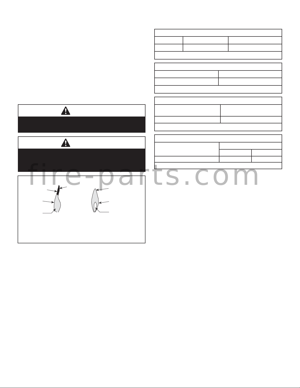
6. Using a manometer, test the inlet and manifold gas pressures.
Inspect for proper burner fl ame appearance (see Figure 11).
The conversion is now complete. To operate your fi replace, refer to
Operating Fireplace in your appliance owner’s manual.
WARNING
Test all gas piping and connections for leaks after
installation or servicing. Correct leaks at once.
WARNING
Never use an open fl ame to check for a leak. Apply
noncorrosive leak detection fl uid to all joints. Bubbles
forming show a leak. Correct all leaks at once.
REFERENCE INFORMATION
Inlet Gas Supply Pressure
Fuel # Minimum Maximum
Propane 11.0” WC (2.74 kPa) 13.0” WC (3.23 kPa)
Table 1
Manifold Gas Supply Pressure
Fuel # Pressure
Propane Gas 10.0” WC / (2.49 kPa)
Table 2
Main Burner Orifi ce Sizes
Drill Size
Propane
Propane Gas / LP
Table 3
Table 4
Fireplace Model
BRT2032 #56
BTU Input
Models
BRT2032 15,000 n/a
High Rate Low-rate
f i r e - p a r t s . c o m
Soot at
Flame Tip
Dark Orange
Flame
No Blue Flame
Center
IMPROPERLY
BURNING FLAME
Soot above
Flame Tip
BURNING FLAME
No Soot at
Flame Tip
Semi-Transparent
Yellow Flame
Blue Flame
Center
PROPERLY
Figure 11 - Inspect for Proper Burner Flame Appearance
127190-01B 5
IHP.us.com

NOTES
______________________________________________________
______________________________________________________
______________________________________________________
______________________________________________________
______________________________________________________
______________________________________________________
______________________________________________________
______________________________________________________
______________________________________________________
______________________________________________________
______________________________________________________
______________________________________________________
______________________________________________________
______________________________________________________
______________________________________________________
______________________________________________________
______________________________________________________
f i r e - p a r t s . c o m
______________________________________________________
______________________________________________________
______________________________________________________
______________________________________________________
______________________________________________________
______________________________________________________
______________________________________________________
______________________________________________________
______________________________________________________
______________________________________________________
______________________________________________________
______________________________________________________
______________________________________________________
______________________________________________________
______________________________________________________
______________________________________________________
______________________________________________________
______________________________________________________
______________________________________________________
______________________________________________________
6
IHP.us.com
127190-01B

NOTES
______________________________________________________
______________________________________________________
______________________________________________________
______________________________________________________
______________________________________________________
______________________________________________________
______________________________________________________
______________________________________________________
______________________________________________________
______________________________________________________
______________________________________________________
______________________________________________________
______________________________________________________
______________________________________________________
______________________________________________________
______________________________________________________
______________________________________________________
f i r e - p a r t s . c o m
______________________________________________________
______________________________________________________
______________________________________________________
______________________________________________________
______________________________________________________
______________________________________________________
______________________________________________________
______________________________________________________
______________________________________________________
______________________________________________________
______________________________________________________
______________________________________________________
______________________________________________________
______________________________________________________
______________________________________________________
______________________________________________________
______________________________________________________
______________________________________________________
______________________________________________________
______________________________________________________
127190-01B 7
IHP.us.com

f i r e - p a r t s . c o m
IHP reserves the right to make changes at any time, without notice, in design, materials, specifi cations, prices and also to discontinue colors, styles and products. Consult your local distributor
for fi replace code information.
Printed in U.S.A. © 2014 Innovative Hearth Products
P/N 127190-01 Rev. B 03/2017
8
1508 Elm Hill Pike, Suite 108 • Nashville, TN 37210
 Loading...