

_________________________________________________________________________________________________________________________
REV. 7-29-15 Page 1 of 4
Model: 4001 & RCKIT4001
Model: 4001& RCKIT4001
INSTALLATION AND OPERATING INSTRUCTIONS
INTRODUCTION
This remote control system was developed to provide safe, reliable, and user-friendly remote control system for gas heating appliances.
The system can be operated manually from the transmitter. The system operates on one of 255 settable security codes on the
transmitter and receiver.
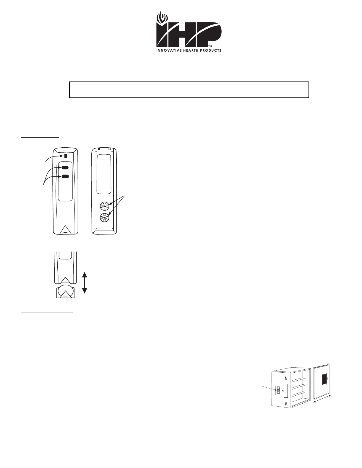
TRANSMITTER
The transmitter has ON and OFF functions that are activated by pressing either
button on the face of the transmitter. When a button on the transmitter is
pressed, a signal light on the transmitter illuminates briefly to verify that a signal
has been sent. Upon initial use, there may be a delay of three seconds before
the remote receiver will respond to the transmitter. This is part of the system’s
design. If the signal light does not illuminate, check the position of the
transmitter’s battery.
The transmitter has (2) code switches located on the back that will need to be set
when installation is complete. Note: Code setting section
The transmitter operates on (1) 3V Button Cell (Included) that powers the RF
signal. Before using the transmitter the 3-volt battery must be installed into the
battery compartments.
Remove the battery holder from the bottom of the transmitter insert the 3-volt
button cell battery in the battery holder with the plus (+) side up. Note the drawing
at the left.
It is recommended that a CR2032 lithium battery always be used for longer
battery life and maximum operational performance.
REMOTE RECEIVER
The remote receiver operates on (4) AA-size 1.5V batteries. It is recommended that ALKALINE batteries be used for longer battery life
and maximum microprocessor performance. IMPORTANT: New or fully charged batteries are essential for proper operation of the
remote receiver.
The remote receiver houses the microprocessor that responds to commands from the transmitter to control system operation. The
remote receiver has a 3-position slide switch for selecting the MODE of operation: OFF/REMOTE/ON
• With the slide switch in the ON position the system will remain on until the slide
switch is placed in the OFF or REMOTE position.
• With the slide switch in the REMOTE position (centered), the system will only operate
if the remote receiver receives commands from the transmitter.
• With the slide switch in the OFF position the system is off.
• It is suggested that the slide switch be placed in the off position if you will be
away from your home for an extended period of time. Placing the slide switch
in the OFF position also functions as a safety “lock-out” by both turning the system off and
OFF and rendering the remote receiver inoperative.
IF YOU CANNOT READ OR UNDERSTAND THESE INSTALLATION INSTRUCTIONS DO NOT
ATTEMPT TO INSTALL OR OPERATE
ON
OFF
+
3 Volt
Battery
Compartment
ON
OFF
SIGNAL
LIGHT
ON/OFF
BUTTONS
FRONT
BACK
LABEL
Code Switches
A
I
M
E
G
C
K
O
1
9
13
5
7
3
11
15
Requires 4-AA 1.5V
alkaline batteries
Battery cover slides on/off
Slide
Switch
REMOTE
ONOFF
900585-00 Rev. NC

_________________________________________________________________________________________________________________________
REV. 7-29-15 Page 2 of 4
Model: 4001 & RCKIT4001
INSTALLATION INSTRUCTIONS
WARNING
This remote control system must be installed exactly as outlined in these instructions. Read all instructions completely before
attempting installation. Follow instructions carefully during installation. Any modifications of the remote control or any of its components
will void the warrant and may be pose a fire hazard.
Do not connect any gas valve or electronic module directly to 110-120VAC power. Consult gas appliance manufacturer’s instructions
and wiring schematics for proper placement of all wires. All electronic modules are to be wired to manufacturer’s specifications.
The following wiring diagrams are for illustration purpose only. Follow instructions from manufacturer of gas valve and/or electronic
module for correct wiring procedures. Improper installation of electric components can cause damage to electronic module, gas valve
and remote receiver.
INSTALLATION
The remote receiver can be either wall-mounted in a standard plastic switch box or placed on or near the fireplace hearth. Preferably,
the remote receiver should be wall-mounted in a plastic switch box. When locating the receiver at the hearth PROTECTION FROM
EXTREME HEAT IS VERY IMPORTANT. Like any piece of electronic equipment, the remote receiver should be kept away from
temperatures exceeding 1300 F inside the receiver case. Battery life is also significantly shortened if batteries are exposed to high
temperatures.
Make sure the remote receiver switch is in the OFF position. It is recommended that 18 gauge solid or stranded wires (included) be
used to make connections between the terminal wiring block on the millivolt gas valve or electronic module and the wire terminals on
the remote receiver. For the best results use wire with no splices and measuring no longer than 20 ft.
WALL MOUNTING
Install (4) AA-size 1.5 ALKALINE batteries in the remote receiver. For best performance, remote receiver batteries should be factory
fresh when installed. Very little battery power is required to operate the remote receiver, but the electronics are tuned to operate best
when battery output is greater than 5.3 volts. Four new AA batteries should provide an output voltage of 6.0 to 6.2 volts. Be sure
batteries are installed with the (+) and (-) ends facing the correct direction.
To attach Cover Plate to Receiver box
Position the receiver as shown in diagram to the left with lower
tab on cover plate inserted into groove of receiver make sure
the cover plate properly aligns with remote receiver. Pull Receiver
up and snap into top tab of cover plate.
Position the cover plate so the word ON is facing up; then, install
the remote receiver into the plastic switch box using the two long
screws provided. Push the White Button over the receiver slide
switch. Make sure the remote receiver code switches has been set
to match the transmitter code switches before completing the
installation Note: Code setting section on page 4.
NOTE: The remote receiver will only respond to the transmitter when the 3-position slide button on the remote receiver is in the
REMOTE position. If the system does not respond to the battery transmitter on initial use, see CODE SETTING SECTION,
and recheck battery positions in the remote receiver.
HEARTH MOUNT
The remote receiver can be placed on the fireplace hearth or under the fireplace, behind the
control access panel. Position where the ambient temperature inside the receiver case does
not exceed 1300 F. Battery life is also significantly shortened if batteries are exposed
to high temperatures. Make sure the remote receiver code switches have been set to
match the transmitter code switches before completing the installation Note: Code setting section.
NOTE: Black Slide Button is used for Hearth Mount applications.
Remote Receiver
Cover Plate
(Rear View)
WALL
Plastic Switch Box
Remote Receiver
Cover Plate
Receiver
Slide
Button
OFF
REMOTE
ON
OFF
ON
R
E
M
O
T
E
Wire terminals
Remote Receiver
REMOTE
ONOFF
Code Switches
Slide Button

_________________________________________________________________________________________________________________________
REV. 7-29-15 Page 3 of 4
Model: 4001 & RCKIT4001
WIRING INSTRUCTIONS
A qualified electrician or a gas technician who is familiar with the gas appliance and gas valves that will be operated by this remote
should install the remote control system. Incorrect wiring connections WILL cause damage to the gas valve or electronic module
operating the gas appliance and may also damage the remote receiver.
WIRING MILLIVOLT VALVES
The remote receiver is connected to the millivolt valve using the TH (thermostat) terminals on the terminal block on the millivolt gas
valve. Connect 18 gauge solid or stranded wires from the remote receiver to the gas valve.
Operation of the remote receiver is similar to that of a thermostat in that both turn the gas
valve on and off based on input signals. A thermostat’s input signals are different temperatures.
The remote receiver’s input signals come from the transmitter.
Connect one of the two wires leading from the receiver to the TH terminal and the other to
the TH/TP terminal on the millivolt gas valve it does not matter which wires go to which
terminal.
WIRING ELECTRONIC SPARK IGNITIONS
The remote control receiver can be connected, in series between a 24VAC transformer
and the TR terminal on the ELECTRONIC MODULE. Connect the hot wire from the
24VAC transformer to either of the wires on the remote receiver. Connect the other wire
on the receiver (wires included) terminal and the TH (thermostat) terminal on the
ELECTRONIC MODULE.
SYSTEM CHECK
MILLIVOLT VALVES AND ELECTRONIC SPARK IGNITION SYSTEMS
Light your gas appliance following the lighting instructions that came with the appliance. Confirm that the pilot flame is on; it must be in
operation for the main gas valve to operate.
• Slide the 3-position button on the remote receiver to the ON position. On millivolt systems the main gas flame (i.e., the fire)
should ignite. On Electronic ignition systems the spark electrode should begin sparking to ignite the pilot (the pilot may ignite
after only one spark). After the pilot flame is lit, the main gas valve should open and the main gas flame should ignite.
• Slide the button to OFF. On millivolt systems the flame should extinguish (the pilot flame will remain on). On electronic ignition
systems the main gas flame and pilot flame should BOTH extinguish.
• Slide the button to REMOTE (the center position), and then press the ON button on the transmitter to change the system to
ON. The main gas flame should ignite. On Electronic ignition systems the spark electrode should begin sparking to ignite the
pilot (the pilot may ignite after only one spark). After the pilot flame is lit, the main gas valve should open and the main gas
flame should ignite.
TERMINAL BLOCK
ON MILLIVOLT
GAS VALVES
TH
TP
TP
TH
THERMOPILE/
PILOT LIGHT
REMOTE
RECEIVER
ELECTRONIC MODULE
TR
TH
REMOTE
RECEIVER
neutral wire
24VAC
hot wire
120VAC
110/24VAC
Transformer

_________________________________________________________________________________________________________________________
REV. 7-29-15 Page 4 of 4
Model: 4001 & RCKIT4001
GENERAL INFORMATION
CODE SETTING
CAUTION: All units are shipped from the factory with the code switch pre-set to the same
codes.
These switches must be re-set to different codes during installation to prevent interference
from another remote.
Each transmitter can use one of 255 set able security codes. It WILL be necessary to
set the transmitter and receiver code switches to a matching security code upon initial
use. If a replacement transmitter or receiver is purchased from your dealer or the factory, the
code switches must be set to match the receiver transmitter code switches. When setting the
code switches set the A through P switch on the transmitter to the same setting as the A
through P switch on the receiver. Then set the 1 through 16 switch on the transmitter
to the same setting as the 1 through 16 switch on the receiver.
Note: A small screwdriver can be used to change these code switches.
Note: The figure to the right showing the code switches on the transmitter and
receiver.
BATTERY LIFE
Life expectancy of the alkaline batteries in the transmitter should be at least 12 months. Check and replace all batteries annually.
When the transmitter no longer operates the remote receiver from a distance it did previously (i.e., the transmitter’s range has
decreased) or the remote receiver does not function at all, the batteries should be checked. It is important that the remote receiver
batteries are fully charged and provides continuous output voltage of at least 5.3 volts. The length of the wire between the remote
receiver and gas valve directly affects the operating performance of the remote system. The longer the wire, the more battery power is
required to deliver signals between the remote receiver and the gas valve. Recommended length is no longer than 20-feet. The
transmitter should operate with as little as 2.5 volts battery power.
TROUBLE SHOOTING
If you encounter problems with your fireplace system, the problem may be with the fireplace itself or it could be with the remote.
Review the fireplace manufacturer’s operation manual to make sure all connections are properly made. Then check the operation of
the remote in the following manner:
• Make sure the batteries are correctly installed in the RECEIVER. One reversed battery will keep receiver from operating properly.
• Check the battery in the Transmitter to make sure it is installed with the (+) side up.
• Check the code settings on the transmitter and receiver to be sure that they are matched settings.
• Be sure the RECEIVER and Transmitter is within 20 to 25-foot operating range.
• Keep RECEIVER from temperatures exceeding 1300 F. Battery life is shortened when ambient temperatures are above 1300 F.
• If RECEIVER is installed in tightly enclosed metal surround, the operating distance will be shortened.
SPECIFICATIONS
BATTERIES: Transmitter 3V button cell (CR2032)
Remote Receiver 6V – 4ea. AA 1.5 Alkaline FCC ID No.’s: transmitter –K9L 4001TX; receiver – K9L 4001RX
Operating Frequency: 433.92MHZ Canadian ISC ID No.’s: transmitter –2439A 4001TX; receiver – 2439A 4001RX
FCC REQUIREMENTS
NOTE: THE MANUFACTURER IS NOT RESPONSIBLE FOR ANY RADIO OR TV INTERFERENCE CAUSED BY
UNAUTHORIZED MODIFICATIONS TO THIS EQUIPMENT. SUCH MODIFICATIONS COULD VOID THE USER’S AUTHORITY
TO OPERATE THE EQUIPMENT.
BACK
LABEL
Code Switches
1
9
13
5
7
3
11
15
A
I
M
E
G
C
K
O
A
I
M
E
G
C
K
O
1
9
13
5
7
3
11
15
RECEIVER TOP
Code Switches
A
I
M
E
G
C
K
O
1
9
13
5
7
3
11
15
HOW TO REGISTER A CLAIM AGAINST WARRANTY
In order for any claim under this warranty to be valid, you must contact IHP dealer/distributor from which you
purchased the product. If you cannot locate the dealer/distributor, then you must notify IHP in writing. IHP must be
notified of the claimed defect in writing within 90 days of the date of failure. Notices should be directed to the IHP
Warranty Department at 1508 Elm Hill Pike, Suite 108; Nashville, TN 37210 or visit our website at www.IHP.us.com.
 Loading...