


USER MANUAL
CO2 SCRUBBER
VERSION DS-2019-09
IHC Hytech B.V.
Ramgatseweg 27
4941 VN Raamsdonksveer
The Netherlands
T +31 88 015 36 00
hytech@royalihc.com
www.ihchytech.com
www.royalihc.com
ROYALIHC.COM

24/7 EMERGENCY LINE
OPERATIONAL AND TECHNICAL ASSISTANCE
+31 88 015 36 00
Copyright 2019 IHC Hytech B.V.
All rights reserved. No part of this publication may be reproduced, stored in a retrieval system, or transmitted
in any form or by any means, electronic, mechanical, photocopying, recording or otherwise, without the prior
written permission of IHC Hytech B.V.
This publication remains the property of IHC Hytech B.V. and may not be passed, loaned or given to any third
party.
IHC Hytech B.V. reserves the right to make changes in design and specifications without notice.
2
IHCHYTECH.COM

PREFACE
ABOUT THIS USER MANUAL
This user manual provides instructions for installing and operating the IHC Hytech CO2 scrubber.
The manual consists of:
Chapter 1 - Introduction
Chapter 2 - Safety precautions
Chapter 3 - Installation
Chapter 4 - Operation
Chapter 5 - Maintenance
INTENDED AUDIENCE
The information in this user manual is intended for operators and maintenance personnel
working with diver decompression chambers and hyperbaric treatment chambers.
CORRECTIONS AND/OR CLARIFICATIONS
During the composition of this manual much attention has been given to avoid errors and mistakes. If during the use of this manual errors or incomplete descriptions are found or if the reader
considers that improvements are necessary to overcome any inaccuracies, please inform us. We
appreciate any comments which will help us to improve our documentation.
For corrections or clarifications please contact:
IHC Hytech B.V.
Documentation Department
Ramgatseweg 27
4941 VN Raamsdonksveer
The Netherlands
E-mail: hytech@royalihc.com
USER MANUAL CO2 SCRUBBER CS-2019-09
3

4
IHCHYTECH.COM

TABLE OF CONTENTS
PREFACE 3
TABLE OF CONTENTS 5
1 INTRODUCTION 7
1.1 GENERAL . . . . . . . . . . . . . . . . . . . . . . 7
1.2 SPECIFICATIONS . . . . . . . . . . . . . . . . . . . 8
1.3 OPTIONAL EQUIPMENT. . . . . . . . . . . . . . . . . 9
1.3.1 CONTAMINATION CANISTER . . . . . . . . . . . 9
2 SAFETY PRECAUTIONS 11
2.1 GENERAL . . . . . . . . . . . . . . . . . . . . . . 11
2.2 WARNING SIGNS . . . . . . . . . . . . . . . . . . . 11
2.3 GENERAL SAFETY MEASURES . . . . . . . . . . . . . . 11
2.3.1 MAINTENANCE AND REPAIR . . . . . . . . . . . 11
3 INSTALLATION 13
3.1 MECHANICAL. . . . . . . . . . . . . . . . . . . . . 13
3.2 ELECTRICAL . . . . . . . . . . . . . . . . . . . . . 13
4 OPERATION 15
4.1 GENERAL . . . . . . . . . . . . . . . . . . . . . . 15
4.2 PERFORMANCE . . . . . . . . . . . . . . . . . . . . 15
4.2.1 PERFORMANCE DIAGRAMS . . . . . . . . . . . . 16
4.3 REPLACING OR REFILLING THE CANISTER . . . . . . . . .17
5 MAINTENANCE 19
5.1 GENERAL . . . . . . . . . . . . . . . . . . . . . . 19
5.2 SPARE PARTS AND ACCESSORIES . . . . . . . . . . . . 19
INDEX 21
USER MANUAL CO2 SCRUBBER CS-2019-09
5

6
IHCHYTECH.COM

INTRODUCTION 1
1.1 GENERAL
The IHC Hytech CO2 scrubber unit removes CO2 from the atmosphere in hyperbaric chambers.
The scrubber has an induced flow fan that pulls breathing gas through a canister filled with soda
lime to adsorb CO2.
The fan motor is designed by IHC Hytech and has completely potted stator electronics. This
protects the motor from environmental impacts such as raised oxygen levels, humidity and
pressure.
The canister can hold approx. 7.5 kg (16.5 lbs) of CO
a bayonet locking mechanism for easy replacement. The canister is provided with internal mesh
of 0.3 mm to keep in the smallest grains.
One scrubber is capable of serving eight persons for more than 6 hours in a chamber with
adequate gas circulation.
To minimise dust forming and increase the duration of the adsorbent, soda lime with a particle
size of 1-2 mm can be used.
adsorbent and is connected to the motor by
2
Figure 1.1 CO2 scrubber
USER MANUAL CO2 SCRUBBER VERSION CS-2019-09
Chapter 1 7

1.2 SPECIFICATIONS
Specifications
Dimensions L 422 mm (16.6 inch) x W 226 mm (8.9 inch) x H 245 mm (9.7
Weight complete unit (empty) 8.3 kg (18.3 lbs)
Weight complete unit (full) 16 kg (35.3 lbs)
Weight canister (empty) 2.3 kg (5.1 lbs)
Weight canister (full) 10 kg (22)
Power supply 24-28VDC, 2A
Rotating speed 1400-3300 rpm
Operating pressure* Max. 42 bar (420 msw)
* = The maximum operating pressure depends on the gas mixture of the atmosphere. For
compressed air, the maximum operating pressure is 10 bar. Adding helium to the mix allows
increase of the maximum operating pressure according to the graph below.
inch)
8 Chapter 1
IHCHYTECH.COM

1.3 OPTIONAL EQUIPMENT
1.3.1 CONTAMINATION CANISTER
The scrubber fan unit can be installed with a contamination canister (2.80.3963). The IHC Hytech
contamination canister removes contamination from breathing gas in enclosed environments. The
special fill of the canister removes all kind of contamination in enclosed environments such as
vomit, urine, feces and sweat.
The following chemical components are eliminated:
• Urea (NH2) 2CO from urine
• Carbon monoxide (CO) from endogenous production
• Acetone (GH
• Hydrogen chloride (HCL) from vomit
• Hydrogen sulphite (H
• Carbonyl sulphite (OCS) from intestinal gas
• Hydrogen (H) from intestinal gas
• Methane (CH
• Carbondisulphite (CS
• Butyric acid (C
COCH3) metabolic and from organic waste
3
S) from feces/intestinal gas
2
) from intestinal gas
4
) from intestinal gas
2
COOH) from intestinal gas
3H1
The contamination scrubber canister contains a special blend of carbon molecular sieves and a
catalyst and is stored in an air tight container. Once the container is opened and the canister is
exposed to the environment it starts to work. The canister lasts for at least 450 hours/person.
Figure 1.2 Canister refill
NOTE
The duration of a canister is calculated as follows:
450 divided by the number of occupants = hours of duration.
Example: A hyperbaric life boat is occupied by 18 persons. The duration of one canister is 450
divided by 18 occupants = 25 hours.
USER MANUAL CO2 SCRUBBER VERSION CS-2019-09
Chapter 1 9

10 Chapter 1
IHCHYTECH.COM

SAFETY PRECAUTIONS 2
2.1 GENERAL
The manufacturer does not accept any responsibility for damage or injuries caused by misuse of
the scrubber.
2.2 WARNING SIGNS
In this manual three types of warning signs can be found on the left of the page.
These warnings indicate possible dangers. The warning signs are:
NOTE
This indicates a situation that requires extra attention.
CAUTION
This indicates a situation that can cause severe damage to the installation and/or can result in
injuries.
WARNING
This indicates a situation that can cause severe injuries or death.
2.3 GENERAL SAFETY MEASURES
2.3.1 MAINTENANCE AND REPAIR
Maintenance and repair jobs must only be performed by qualified personnel.
It is strictly forbidden to modify the scrubber in any way without written permission from the
manufacturer.
11 Chapter 2
IHCHYTECH.COM

USER MANUAL CO2 SCRUBBER VERSION CS-2019-09
Chapter 2 12

INSTALLATION 3
3.1 MECHANICAL
The scrubber can be mounted in any position, but vertical position is preferred. If the scrubber is
mounted in vertical position, keep the motor on the bottom side for easy changing of the
canister.
NOTE
A free space of at least 75 mm (3”) must be provided on each side of the unit to ensure proper
gas flow. Also keep free space on the side of the canister for removal of the canister.
3.2 ELECTRICAL
The scrubber can be used with a pre-set speed or external speed control function. Use the
specified pins on the connector and place the jumper inside the scrubber to configure the desired
function. See table and pictures for pre-set speed and external speed configuration.
1
Figure 3.1 Electrical connections
2
5
3
4
6
7
USER MANUAL CO2 SCRUBBER VERSION CS-2019-09
Chapter 3 13
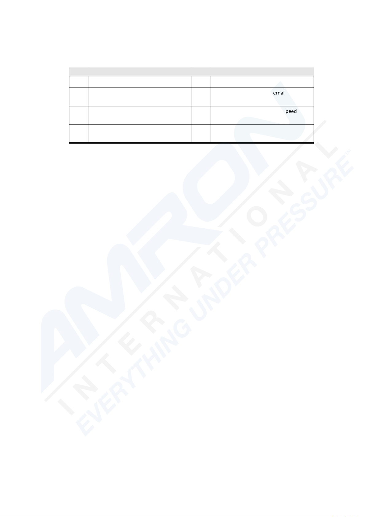
ID Description ID Description
1 Black wire (24 VDC) 5 Jumper
2 White wire (0 VDC) 6 Jumper in position for external speed
control
3 Red wire (0 - 10 VDC speed control
signal referenced to pin 2, optional)
4 Green wire (rpm signal referenced to
pin 2, optional)
7 Jumper in position for pre-set speed
14 Chapter 3
IHCHYTECH.COM

OPERATION 4
4.1 GENERAL
The scrubber is switched on or off by the power supply outside of the chamber.
WARNING
Do not install the switches inside the chamber to avoid the risk of fire.
4.2 PERFORMANCE
The CO2 scrubber is designed to run continuously during diving operations. The performance of
the scrubber is influenced by a number of environmental factors such as:
• The type of adsorbent
• Chamber pressure
• CO2 production (number of persons in the chamber)
• Humidity
• Temperature
• Motor speed
The service life of a canister filling depends on the above mentioned factors.
NOTE
The O
and CO2 levels inside the chamber must be continuously monitored. The scrubber must
2
always be used in combination with an oxygen make-up system. If the CO2 level starts rising, the
canister should be refilled or replaced. If the oxygen level inside the chamber drops, oxygen must
be added to the chamber atmosphere.
USER MANUAL CO2 SCRUBBER VERSION CS-2019-09
Chapter 4 15

4.2.1 PERFORMANCE DIAGRAMS
4.2.1.1 PERFORMANCE AT 50 MSW
4.2.1.2 PERFORMANCE AT 18 MSW
16 Chapter 4
IHCHYTECH.COM

4.2.1.3 PERFORMANCE AT 9 MSW
4.3 REPLACING OR REFILLING THE CANISTER
A
Figure 4.1 Canister
Before replacing or refilling the canister, switch off the scrubber motor.
1. Remove the canister from the scrubber motor by turning the canister counter-clockwise (A).
2. Place the canister on the bayonet with the cover plate facing upwards (B).
3. Remove the cover plate by turning it counter-clockwise (B).
4. Replace the adsorbent.
5. Mount the cover plate.
6. Mount the canister on the scrubber motor.
7. The scrubber motor is now ready for use.
USER MANUAL CO2 SCRUBBER VERSION CS-2019-09
B
Chapter 4 17

18 Chapter 4
IHCHYTECH.COM
MAINTENANCE 5
5.1 GENERAL
The CO2 scrubber does not require any maintenance other than refilling the canister if the
adsorbent becomes ineffective. If the motor fails, the whole unit should be replaced. Replacing
the motor unit can be done in a matter of seconds. After removing the canister, the motor unit
can be removed from the mounting bracket by loosening the locking screw.
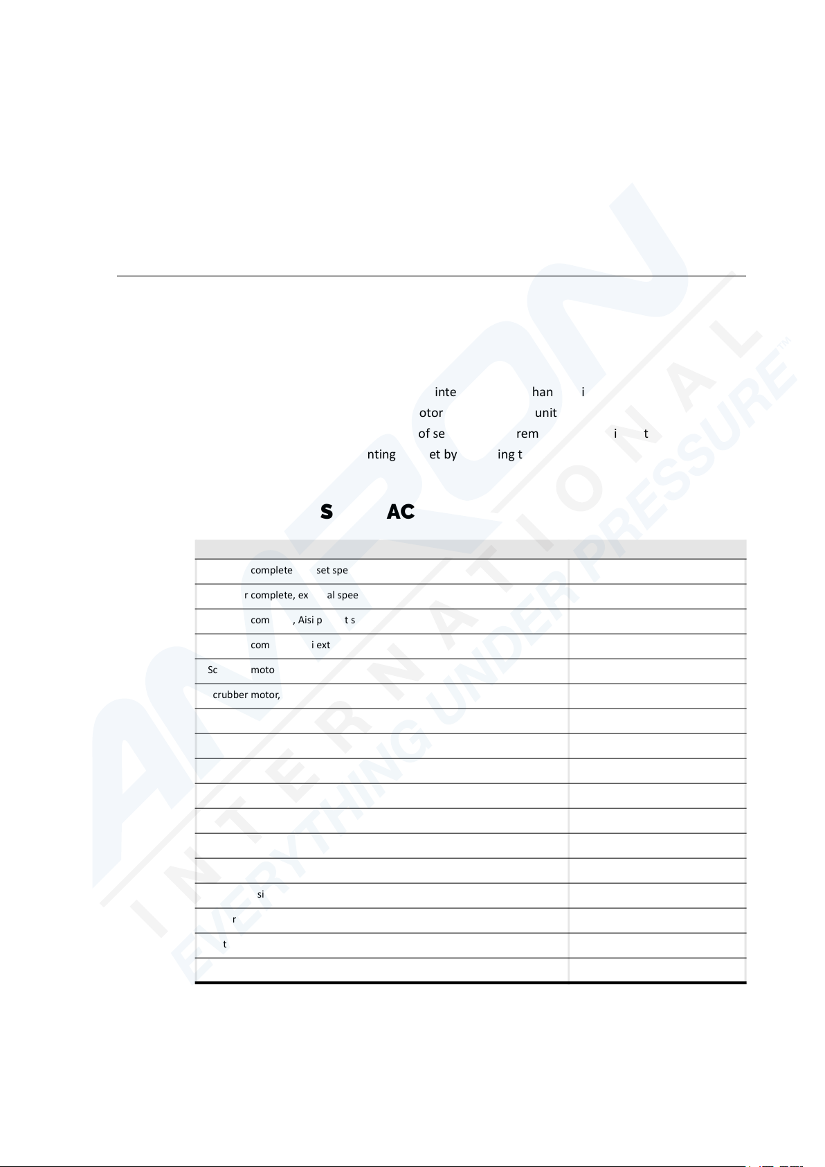
5.2 SPARE PARTS AND ACCESSORIES
Description Part number
Scrubber complete, pre-set speed 3.80.1018-1V
Scrubber complete, external speed control 3.80.1018-1E
Scrubber complete, Aisi pre-set speed 3.80.2938-1V
Scrubber complete, Aisi external speed control 3.80.2938-1E
Scrubber motor, pre-set speed 3.80.1018-2V
Scrubber motor, external speed control 3.80.1018-2E
Canister assembly (including canister O-ring) 3.80.973
Canister O-ring 105.00 x 6.00 H.70.00310
Canister Cover plate 3.80.2343
Sofnolime (Sodalime) CO2 absorbent T.99.02896
Contamination canister 2.80.3963
Refill Contamination canister T.98.00552
Motor Housing O-ring 75.00 x 6.00 H.70.00292
Motor Housing O-ring 72.00 x 2.50 H.70.00293
Motor Cover plate O-ring 14.00 x 2.50 H.70.00291
Motor lid\ \Scrubber/Heater Motor\AISI316L/1.4404 3.50.5932
Contra connector (motor) H.10.00133
19 Chapter 5
IHCHYTECH.COM

USER MANUAL CO2 SCRUBBER VERSION CS-2019-09
Chapter 5 20

INDEX
P
PERFORMANCE . . .15
PERFORMANCE DIA-
GRAMS . . . . . .16
A
ADSORBENT . . . . 7
C
CANISTER . . . . 17
CANISTER . . . . . 7
CONNECTIONS . . 13
CONTAMINATION CAN-
ISTER . . . . . . . 9
D
DURATION . . . . . 9
E
R
REFILL . . . . . . . 9
S
SAFETY . . . . . .11
SAFETY MEASURES .11
SAFETY MEASURES .11
SCRUBBER . . . . . 7
SPARE PARTS . . . .19
SPECIFICATIONS . . 8
SPEED . . . . . . .13
W
WARNING SIGNS . .11
ELECTRICAL . . . 13
ELECTRICAL CONNEC-
TIONS . . . . . . 13
F
FAN MOTOR . . . . . 7
M
MAINTENANCE . . 11
MAINTENANCE . . 19
MAINTENANCE AND RE-
PAIR . . . . . . . 11
USER MANUAL CO2 SCRUBBER CS-2019-09
21
 Loading...