

Page 1
A. Package Contents.............................................................
t
5
@
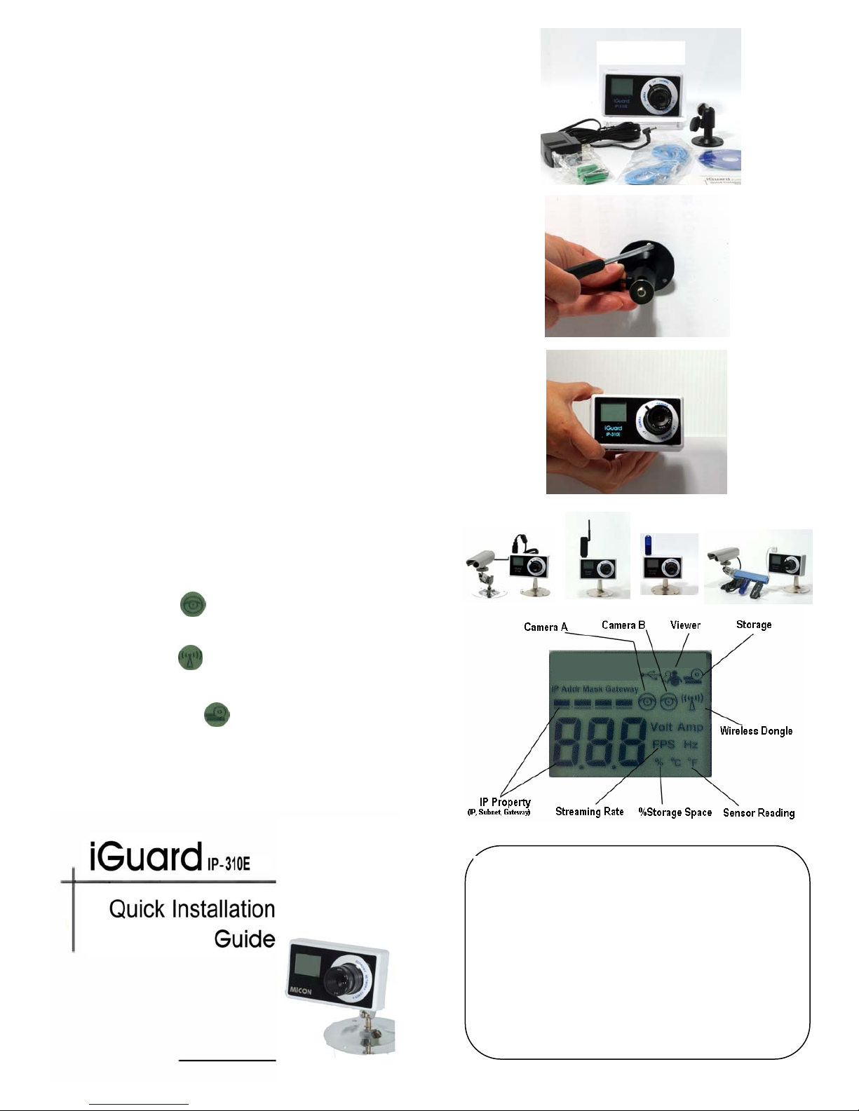
A standard package should contain the following items. If
any of these items are missing, please contact your d ealer.
• iGuard IP-310E IP Camera
• DC 5.3V Power Adaptor.
• Mounting Bracket
• Ethernet Cable
• iGuard Utility CD
• This Quick Installation Guide
B. Camera Installation...........................................................
1. Prepare for the Installation
You need to provide power and LAN access (if you
choose to install the camera via its lan port) near the
location where the camera will be installed. Do not cu
and extend the AC adapter. Use a proper extension
cord if necessary instead.
2. Mount the Camera
Mount the bracket first (You may wish to use the
included anchors to secure the bracket). Attach the
camera to the bracket’s universal panning head.
3. Adjust the Camera Angle
Loosen the knob on the bracket’s universal panning
head and adjust the camera to the desirable angle.
Hand-tighten the knob.
4. Attach the AC and Network Cable
Plug the Ethernet cable and AC/DC adapter to the RJ4
and Power-In jacks on the bottom of the camera.
Please use the included power supply to power the
camera (Note: this camera supports 5.3V DC.).
C. Expansion Installation (Optional)...................................
This iGuard IP camera has a built-in USB exp ansion port,
to which a large selection of USB cameras, wireless
dongles, and USB storage devices can be attached.
1. Second Camera
The second camera icon
will lid on the LCD if a
compatible USB camera is attached to the unit.
2. Wireless Dongle
The wireless icon will lid on the LCD if a compatible
WiFi dongle is attached.
3. USB Storage Device
A USB Disk icon will lid on the LCD if a com patible
USB disk is attached.
4. USB Hub
You can use a USB hub if you wish to use two or
more of the above add-ons.
MICON TECHNOLOGY, INC.
13608 Merriman Road, Livonia, MI 48150, USA
Tel: 734-261-3828, Fax: 734-261-4139
Tech Support: 734-422-6171
www.iguard.com
or www.micon.com
sales
micon.com
Page 2
D. System Requirements ......................................................
.
.
p
1 Remote PC
• CPU: Pentium III 450 MHz and above
• Memory 128 MB and above
• VGA card resolution at least 800 x 600
• CD ROM Drive
• Java enabled and compliant Web browser (IE 5.0 and above)
2 Router/Switch
• A router that supports DHCP and Port Forwarding
• A Switch if your cable/DSL modem has a built-in router.
3 Internet Connection
• Broadband internet connection with a minimum of 384K bandwidth
• HTTP and UTP protocol enabled
E. Network Connection .........................................................
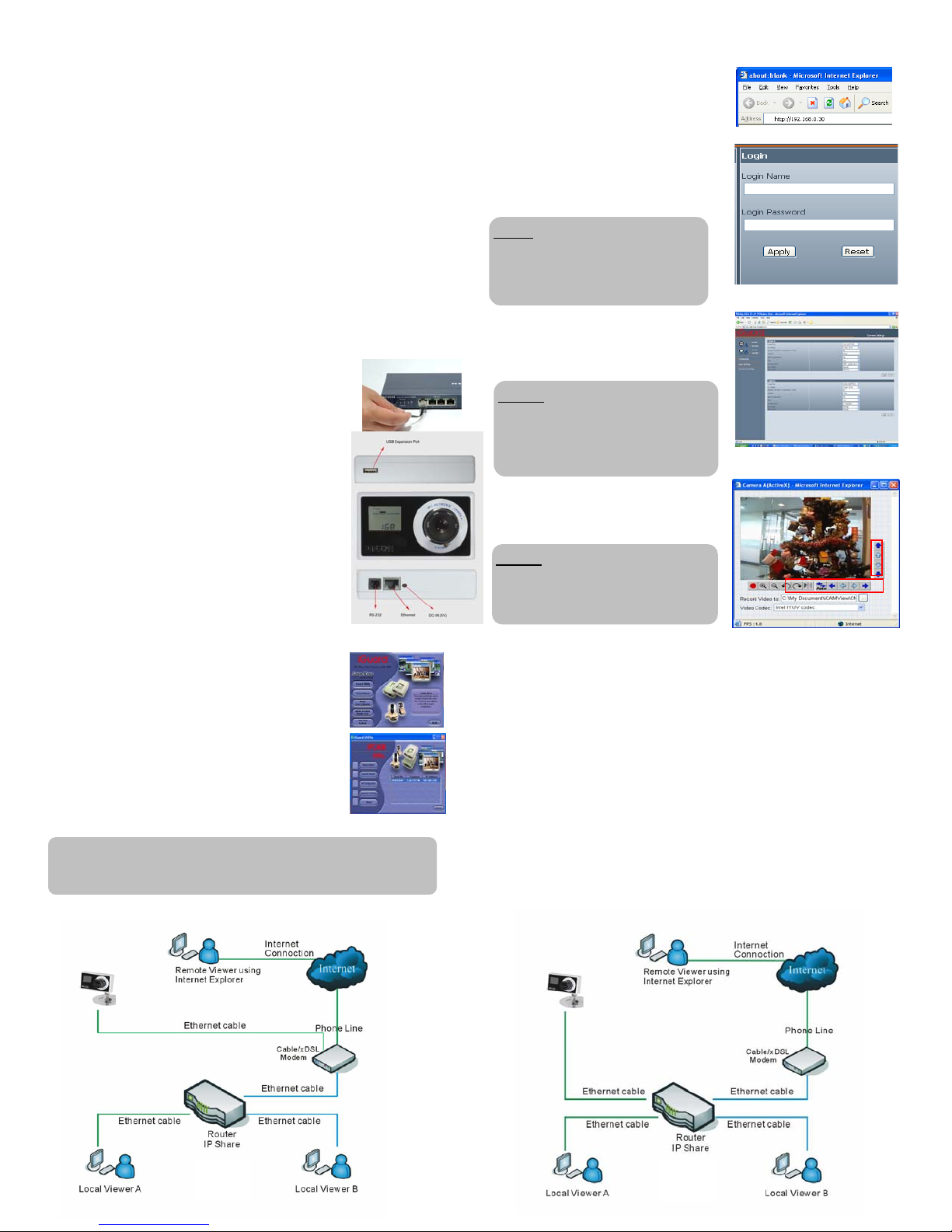
1 Cable/DSL Modem Connection (Fig.1)
You can connect the IP-310E to a cable/DSL modem
directly if you have dedicated internet connection.
2 Router/Switch Connection (Fig.2)
If you use a router to share internet connection then
your camera has to be connected to the router which
in turn is connected to the cable/DSL modem.
3 IP Configuration
By default IP-310E will obtain an IP address assigned
by a DHCP-enabled router, and display that IP on the
LCD screen. You can skip directly to Step G.1 to
configure and monitor the camera via its web
manager.
G. Local Monitoring (behind the router) ...................................
1. Launch IE or any Java Enabled Browser,
enter the IP address that is assigned to
the IP-270E in Step. F
2. Enter your User Name and Password* to
login.
The default user ID and Password is not
defined. Press “Enter” twice or click on
“Apply” to login
UNOTE:
* For some shipment, the user name maybe
defined as “admin”; the password is the
same as the master passwo rd which is on
the serial # label on the camera.
3. Click on ‘ActiveX’ or ‘Sun Java’ on
Camera A or B to view the video,
based on the browser on your PC
UNOTE:
You may be prompted to install an
Active-X component if this is your first
time visiting the camera click “OK” to
roceed
4. Click on the Red round button to
record images to the destination
specified in the path.
UNOTE:
The Pan/Tilt control buttons are for the
optional second cameras that support PT
functions.
F. Software Installation (iGuard Utility)................................
1. Place the iGuard Utility CD in the CDROM, the
installation program shall start automatically.
2. Install the iGuard Utility and iGuard View
programs according to the instruction on the
computer screen
3. Once installation is completed, click the ‘iGuard
Utility’ icon to start the program.
4. The iGuard utility will search for any iGuard unit
on the local network and display the DHCP
assigned IP address*. Click on the iGuard IP
camera to launch the iGuard web manager.
* A DHCP server is required. The PC and the camera must be on
the same subnet (behind the same router) for the PC to “see” the
camera..
H. Remote Monitoring (From Internet)......................................
1. If you have a Static Public IP… (Fig.1)
Follow the same procedure in Step G above. All you have to do is
adjusted the TCP/IP property in the network section of iGuard’s web
control software to the assigned parameters.
2. If have a Dynamic Public IP and you share your internet
connection through a router...(Fig.2)
This is a typical situation if you have a consumer grade broadband
service. There are three major issues that need to be addressed:
a. DDNS service (to keep track your IP address)
b. Port forwarding (Router Programming)
c. Firewall
If you are not familiar with these network terms, then you will probably
need a network technician to help to setup the iGuard. Please refer to
the user’s manual on the utility CD for more information.
Fig.1
Fig.2
 Loading...