

Page 1
Quick Start Guide
1
1
2
1
2
3
3
4
4
2
1
1
234
1
3
2
4
4
123
4
2
1
1
2
Cloud-Enabled Indoor/Outdoor Access Point
SunSpot™ Wave2 AC2600
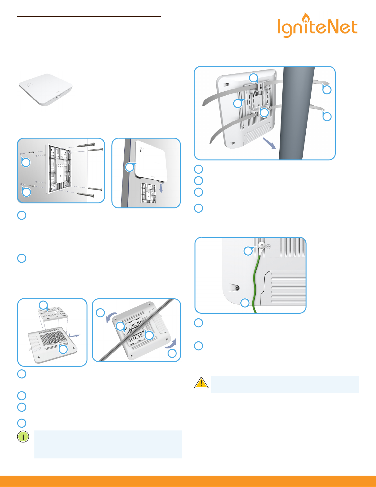
1. Unpack the AP
◆
SunSpot™ Wave2 AC2600
◆
Wall/Ceiling mounting bracket and
securing screw
◆
Wall-mount kit — 4 screws, 4 wall plugs
◆
Universal AC/DC power adapter
2. Mount the AP
a. Mounting the AP on a Wall
At the installation location on the wall, use the wall/ceilingmount bracket to mark four holes for the wall plugs and
screws (included in wall-mount kit).
Drill four holes for the wall plugs, and then insert the plugs
and tap them flush with the wall surface.
Use the four screws to secure the bracket to the wall.
With its ports facing down, place the AP over the bracket
flanges and then slide it down until it snaps into its secured
position.
Do not let go of the AP until you confirm that it is secure.
c. Mounting the AP on a Pole (requires optional pole-mount kit)
Attach the pole-mount bracket to the back of the AP.
Use the included screw to secure the bracket to the AP.
Feed the two steel-band clamps through the pole-mount
bracket mounting points.
Fasten the steel-band clamps around the pole to secure the
AP to the pole.
3. Ground the AP
b. Mounting the AP on a Ceiling
Place the wall/ceiling-mount bracket over the mounting
flanges on the back of the AP, and then slide it up until it
snaps into its secured position.
Use the included screw to secure the bracket to the AP.
Press the retention clips of the wall/ceiling-mount bracket
against the ceiling T-bar.
Rotate the AP until the T-bar snaps into place.
Note:
different sizes of suspended ceiling T-bars. The position
The wall/ceiling-mount bracket supports two
illustrated above is for 15 mm bars. Use the position at a 90
degrees angle for 24.5 mm bars.
ignitenet.com
Ensure the structure on which the unit is to be mounted is
properly grounded and in compliance with local and
national electrical codes.
Verify that there is a good electrical connection to a
grounding point (no paint or isolating surface treatment).
Use the included (M4) screw to attach a grounding wire (not
included) to the grounding point on the unit, and then to
ground.
Caution:
The earth connection must not be removed
unless all supply connections have been disconnected.
– 1 –
E032018-CS-R02
Page 2
Quick Start Guide
2
3
1
123
1
2
1
2
1
3
2
1
2
3
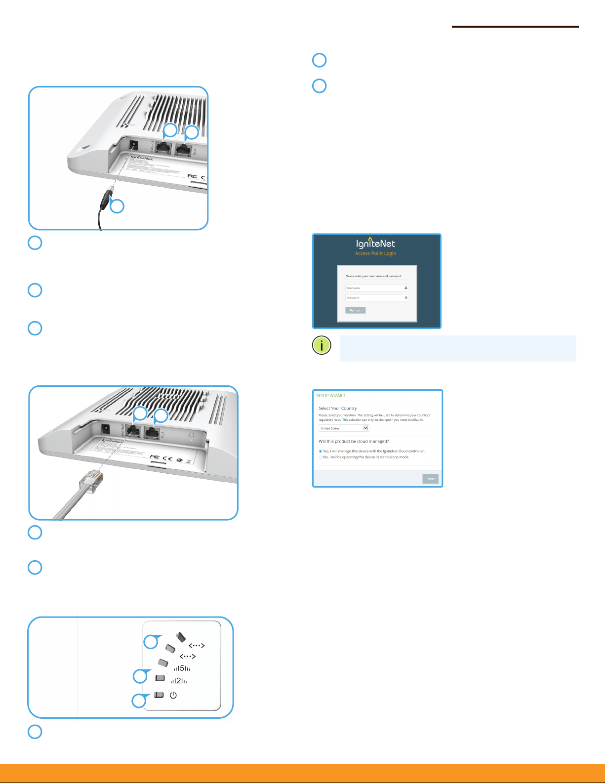
Log in to the web interface
using the default settings:
◆
Login Name — root
◆
Password — admin123
Select the country of
operation for the AP. Setting
the correct country ensures
that the radios operate within
local regulations specified for
Wi-Fi networks.
4. Connect Cables
a. Using the AC/DC Power Adapter
Connect the cable from the AC/DC power adapter to the DC
power jack on the AP.
Connect the power adapter to a nearby AC power source
(100-240 VAC, 50/60 Hz).
Connect Category 5e or better cable to the ETH1/PoE RJ-45
port.
Connect the other end of this cable to a LAN switch.
(Optional) Connect local LAN devices to the other RJ-45 port
on the AP using Category 5e or better cable.
This 1000BASE-T port is labeled ETH2.
During normal operation, the wireless LEDs should be on/
blinking green.
The ETH1/PoE port link/activity LED should be on/blinking
green.
When connected, the ETH2 port link/activity LEDs should
also be on/blinking green.
6. Connect to the Web User Interface
To access the web interface, connect a PC directly to the AP’s ETH2
RJ-45 port. In a web browser, enter the AP’s default management IP
address of 192.168.2.1 to access the web login page.
If you want to connect to the web interface using the ETH1/PoE
port, the IP address is automatically assigned through DHCP by
default. If a DHCP server is unreachable, the ETH1/PoE port reverts
to a fallback IP address of 192.168.1.20.
Note:
To reset the AP to factory default settings, press and
hold down the AP’s Reset button for 5 seconds.
b. Using a PoE Power Source
Connect Category 5e or better cable to the ETH1/PoE
RJ-45 port, and the other end of this cable to an 802.3af PoE
LAN switch.
(Optional) Connect local LAN devices to the other ETH2
RJ-45 port on the AP using Category 5e or better cable.
5. Verify AP Operation
7. Complete the Setup Wizard
Manage the AP with the IgniteNet Cloud Controller
Go to cloud.ignitenet.com to register your AP.
Log in and select Devices from the menu. Click Add Device and
enter the AP serial number and MAC address to register the AP with
your cloud network. The serial number and MAC address can be
found on the product packaging or label.
Manage the AP in Stand-Alone Mode
If you select to manage the AP in stand-alone mode, use the web
interface to manually make your configuration changes.
For more information on AP configuration in stand-alone mode,
refer to the HeliOS User Manual, which can be downloaded from
ignitenet.com/support.
The power LED should be on amber.
– 2 –
Page 3

Safety and Regulatory Information
FCC Class B
This equipment has been tested and found to comply with the limits for
a Class B digital device, pursuant to Part 15 of the FCC Rules. These limits
are designed to provide reasonable protection against harmful
interference in a residential installation. This equipment generates, uses
and can radiate radio frequency energy and, if not installed and used in
accordance with the instructions, may cause harmful interference to
radio communications. However, there is no guarantee that interference
will not occur in a particular installation. If this equipment does cause
harmful interference to radio or television reception, which can be
determined by turning the equipment off and on, the user is
encouraged to try to correct the interference by one of the following
measures:
◆ Reorient or relocate the receiving antenna
◆ Increase the separation between the equipment and receiver
◆ Connect the equipment into an outlet on a circuit different from
that to which the receiver is connected
◆ Consult the dealer or an experienced radio/TV technician for help
FCC Caution: Any changes or modifications not expressly approved by
the party responsible for compliance could void the user’s authority to
operate this equipment.
This device complies with Part 15 of the FCC Rules. Operation is subject
to the following two conditions: (1) This device may not cause harmful
interference, and (2) this device must accept any interference received,
including interference that may cause undesired operation.
For product available in the USA/Canada market, only channel 1–11 can
be operated. Selection of other channels is not possible.
This transmitter must not be co-located or operating in conjunction with
any other antenna or transmitter.
Operations in the 5.15-5.25GHz band are restricted to indoor usage only.
IMPORTANT NOTES:
FCC Radiation Exposure Statement:
This equipment complies with FCC radiation exposure limits set forth for
an uncontrolled environment.
Professional Installation Instructions:
1. Installation personal
This product is designed for specific applications and should be installed
by qualified personnel who have knowledge of RF and its related
regulations. A general user shall not attempt to install or modify the
equipment configuration.
2. Installation location
To meet regulatory RF exposure requirements, this product shall be
installed at a location where, during normal operations, the radiating
antenna is at least 45cm away from any nearby persons.
3. External antenna
Use only the antennas which have been approved by the applicant.
Using non-approved antenna(s) is prohibited and may produce
unwanted spurious or excessive RF transmitting power which may lead
to a violation of FCC limits.
4. Installation procedure
Quick Start Guide
Please refer to this equipment’s user manual for the procedure details.
5. Warning
The installation position must be carefully selected so that the final
output power does not exceed the limit set forth in relevant regulations.
Violation of output power regulations could lead to serious federal
penalties.
Industry Canada
This device complies with Industry Canada license-exempt RSS
standard(s). Operation is subject to the following two conditions: (1) this
device may not cause interference, and (2) this device must accept any
interference, including interference that may cause undesired operation
of the device.
Le présent appareil est conforme aux CNR d'Industrie Canada
applicables aux appareils radio exempts de licence. L'exploitation est
autorisée aux deux conditions suivantes : (1) l'appareil ne doit pas
produire de brouillage, et (2) l'utilisateur de l'appareil doit accepter tout
brouillage radioélectrique subi, même si le brouillage est susceptible
d'en compromettre le fonctionnement.
For product available in the USA/Canada market, only channel 1~11 can
be operated. Selection of other channels is not possible.
Pour les produits disponibles aux États-Unis / Canada du marché, seul le
canal 1 à 11 peuvent être exploités. Sélection d'autres canaux n'est pas
possible.
Dynamic Frequency Selection (DFS) for devices operating in the bands
5250- 5350 MHz, 5470-5600 MHz and 5650-5725 MHz.
Sélection dynamique de fréquences (DFS) pour les dispositifs
fonctionnant dans les bandes 5250-5350 MHz, 5470-5600 MHz et 56505725 MHz.
The device for operation in the band 5150-5250 MHz is only for indoor
use to reduce the potential for harmful interference to co-channel
mobile satellite systems.
les dispositifs fonctionnant dans la bande 5150-5250 MHz sont réservés
uniquement pour une utilisation à l'intérieur afin de réduire les risques
de brouillage préjudiciable aux systèmes de satellites mobiles utilisant
les mêmes canaux.
IMPORTANT NOTE:
IC Radiation Exposure Statement:
This equipment complies with IC RSS-102 radiation exposure limits set
forth for an uncontrolled environment. This equipment should be
installed and operated with minimum distance 20 cm between the
radiator and your body.
Cet équipement est conforme aux limites d'exposition aux
rayonnements IC établies pour un environnement non contrôlé. Cet
équipement doit être installé et utilisé avec un minimum de 20 cm de
distance entre la source de rayonnement et votre corps.
CE Statement
This equipment complies with EU radiation exposure limits set forth for
an uncontrolled environment. This equipment should be installed and
operated with minimum distance 20 cm between the radiator and your
body.
The device is restricted to indoor use only when operating in the 5150 to
5350 MHz frequency range.
All operational modes:
2.4 GHz: 802.11b, 802.11g, 802.11n (HT20), 802.11n (HT40)
– 3 –
Page 4

5 GHz: 802.11a, 802.11n (HT20), 802.11n (HT40), 802.11ac (VHT20),
802.11ac (VHT40), 802.11ac (VHT80), 802.11ac (VHT160)
The frequency and maximum transmitted power limit in EU are listed as
below:
2412-2472 MHz: 20 dBm
5150-5350 MHz: 23 dBm
5500-5700 MHz: 30 dBm
AT BE BG CH CY CZ
DE DK EE EL ES FI
FR HR HU IE IS IT
LI LT LU LV MT NL
NO PL PT RO SE SI
SK TR UK
The abbreviations of the countries, as prescribed in above table, where
any restrictions on putting into service or any requirements for
authorization of use exist.
Europe - EU Declaration of Conformity
Hereby, IgniteNet Inc. declares that the radio equipment type:
SunSpot™ Wave2 AC2600 is in compliance with Directive 2014/53/EU.
The full text of the EU declaration of conformity is available at the
following internet address:
www.ignitenet.com -> support.
Japan Statement
5 GHz band (W52, W53): Indoor use only
NCC Statement (Taiwan)
低功率電波輻射性電機管理辦法
第十二條 經型式認證合格之低功率射頻電機,非經許可,公司、商號或
使用者均不得擅自變更頻率、加大功率或變更原設計之特性及功能。
第十四條 低功率射頻電機之使用不得影響飛航安全及干擾合法通信;經
發現有干擾現象時,應立即停用,並改善至無干擾時方得繼續使用。前
項合法通信,指依電信法規定作業之無線電通信。低功率射頻電機須忍
受合法通信或工業、科學及醫療用電波輻射性電機設備之干擾。
Warnings and Cautionary Messages
Warning:
parts.
Warning:
out by qualified personnel only.
Warning:
connect the field ground lead on the tri-pole power plug to a
valid earth ground line to prevent electrical hazards.
Caution:
measures to prevent electrostatic discharge when handling this
equipment.
Caution:
port. This may damage this device.
Caution:
that conform to FCC standards.
This product does not contain any serviceable user
Installation and removal of the unit must be carried
When connecting this device to a power outlet,
Wear an anti-static wrist strap or take other suitable
Do not plug a phone jack connector in the RJ-45
Use only twisted-pair cables with RJ-45 connectors
Quick Start Guide
Hardware Specifications
Chassis
Size (L x W x H:) 218.8 x 223.8 x 32 mm (8.6 x 9.4 x 1.38 in.)
Weight 850 g (1.87 lb)
Temperature Operating: -30 °C to 55 °C (-22 °F to 131 °F)
Storage: -40 °C to 70 °C (-40 °F to 158 °F)
Humidity Operating: 10% to 90% (non-condensing)
Network Interfaces
Ports ETH1/PoE Port: 1000BASE-T, 802.3af PoE
ETH2 Port: 1000BASE-T
2.4 GHz Radio IEEE 802.11b/g/n
5 GHz Radio IEEE 802.11a/n/ac
Radio Frequencies 2412-2462 (FCC, IC, NCC)
2412-2472 (CE, AU, MIC, SRRC))
5150–5250 (FCC, IC, CE, AU, MIC, NCC, SRRC)
5250–5350 (CE, MIC, AU)
5470–5725 (CE, MIC, AU)
5725–5850 (FCC, IC, NCC, AU, SRRC)
Power Supply
AC Power Adapter Input: 100-240 VAC, 50-60 Hz, auto-sensing
Output: 12 VDC, maximum 2.0 A
802.3at PoE (Eth0) IEEE 802.3at PSE
Power Consumption 24 W maximum
Regulatory Compliances
Radio EN300 328 V2.1.1(2016-11)
EN301 893 V2.1.1(2017-03)
47 CFR FCC Part 15.247
47 CFR FCC Part 15.407
IC RSS-247
IC RSS-247 Issue 1
AS/NZS 4268: 2009
Emissions EN 301 489-1 V2.2.1 (2017-02)
EN 301 489-17 V3.1.1 (2017-02)
EN 55032:2012/AC2013
EN 55024:2010
AS/NZS CISPR 32:2013,Class B
47 CFR FCC Rules and Regulations Part 15
Subpart B, Class B Digital Device
Canada Standard ICES-003, Issue 6, Class B
Manufacturer Accton Technology Corporation
1, Creation 3rd Rd., Hsinchu Science Park,
Hsinchu 30077,
Taiwan, R.O.C
– 4 –
 Loading...