

Page 1
3
1
2
123
4
2
1
3
1
2
3
4
1
2
1
2
2
1
1
2
Q u i c k S t a r t G u i d e
Cloud-Enabled Outdoor 60GHz PTMP + 5GHz + 2.4GHz
Model name(HVIN)
ML-60-10G-360
:
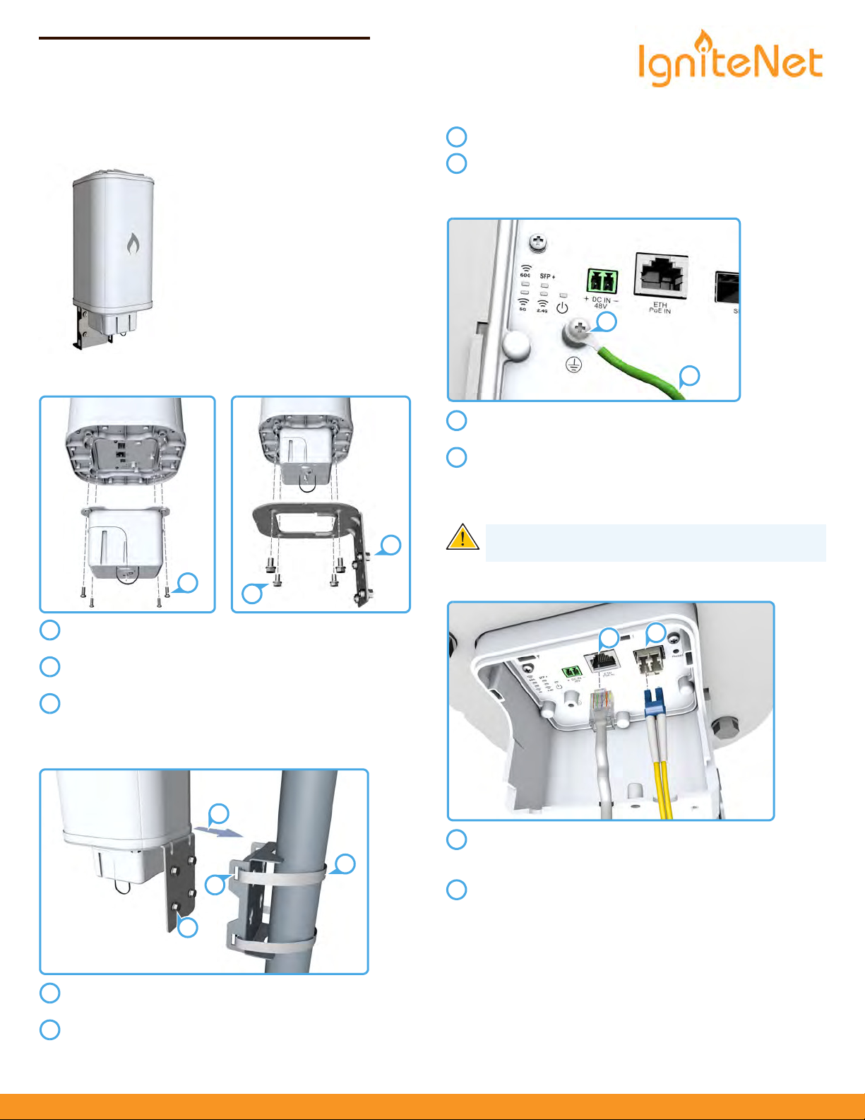
1. Unpack the MetroLinq
Package Contents
◆
MetroLinq™ 10G Tri-Band Omni
◆
Pole-mount kit — bracket, 8
bolts,
Tools/Items Required
◆
13 mm socket wrench
◆
Flat-head screwdriver
◆
Ethernet cables
2. Assembly
Mount the MetroLinq onto the pole-mount bracket.
Tighten the four bolts to secure the MetroLinq.
4. Grounding
Ensure the structure on which the unit is to be mounted is
properly grounded and in compliance with ETSI ETS 300 253.
Verify that there is a good electrical connection to a
grounding point (no paint or isolating surface treatment).
Use the included (M4) screw to attach a grounding wire (not
included) to the grounding point on the unit, and then to
ground.
Caution:
unless all supply connections have been disconnected.
The earth connection must not be removed
Attach the port cover to the base of the unit using the
included four screws.
Attach the mounting bracket to the base of the unit using
four bolts.
Insert four bolts into the holes in the mounting bracket,
leaving the heads a few millimeters from the bracket.
3. Mount the MetroLinq on a Pole
F
eed the two steel-band clamps through the pole-mount
bracket mounting points.
ignitenet.com
Fasten the steel-band clamps around the pole to secure the
pole-mount bracket to the pole.
5. Connect Cables
Connect outdoor-rated Category 5e or better cable to the
ETH PoE IN RJ-45 port. (The other end of this cable connects
to the PoE power injector.)
Install a 10G SFP+ transceiver in the SFP+ port, and then
connect fiber optic cabling to the transceiver.
– 1 –
The following transceivers are supported:
◆
10GBASE-SR
◆
10GBASE-LR
-60-10G-360
ML
E122017-CS-R01
Page 2
Quick Start Guide
1
2
3
123
1
2
1
2
3
1
3
2
123
Log in to the web interface
using the default settings:
◆
Login Name — root
◆
Password — admin123
6. Connect Power
a. PoE Power
Connect outdoor-rated Category 5e or better cable from the
MetroLinq to the POE port on the power injector.
Connect Category 5e or better cable from the LAN port on
the power injector to a LAN switch.
Connect the power cord to the power injector and to a
nearby AC power source (100-240 VAC, 50/60 Hz).
Caution:
only. Never mount the power injector outside with the
MetroLinq unit.
b. DC Power
The power injector is designed for indoor use
7. Verify MetroLinq Operation
The Power LED should be on green.
When connected, the SFP+ link/activity LED should be on/
blinking green.
During normal operation, the wireless LEDs should be on/
blinking green.
8. Connect to the Web User Interface
To access the web interface, connect a PC directly to the MetroLinq’s
ETH PoE IN RJ-45 port. In a web browser, enter the default
management IP address of 192.168.1.20 to access the web login
page.
Note:
To reset the MetroLinq to factory default settings,
Warning:
Before wiring the DC block or connecting power
press and hold down the AP’s Reset button for 5 seconds.
to the device, ensure that power to the feed lines is turned
off at the supply circuit breaker or disconnected from the
power bus.
Connect the DC power feed wire to the DC block “+” pin.
Connect the ground/return wire to the DC block “-” pin.
– 2 –
Page 3

9. Complete the Setup Wizard
Select the country of
operation for the AP. Setting
the correct country ensures
that the radios operate within
local regulations specified for
Wi-Fi networks.
Manage the MetroLinq with the IgniteNet Cloud Controller
Go to cloud.ignitenet.com to register your AP.
Log in and select Devices from the menu. Click Add Device and
enter the MetroLinq serial number and MAC address to register the
MetroLinq with your cloud network. The serial number and MAC
address can be found on the product packaging or label.
Manage the MetroLinq in Stand-Alone Mode
If you select to manage the MetroLinq in stand-alone mode, use the
web interface to manually make your configuration changes.
For more information on MetroLinq configuration in stand-alone
mode, refer to the User Manual, which can be downloaded from
ignitenet.com/support.
Quick Start Guide
Safety and Regulatory Information
FCC Class B
This equipment has been tested and found to comply with the limits for
a Class B digital device, pursuant to Part 15 of the FCC Rules. These limits
are designed to provide reasonable protection against harmful
interference in a residential installation. This equipment generates, uses
and can radiate radio frequency energy and, if not installed and used in
accordance with the instructions, may cause harmful interference to
radio communications. However, there is no guarantee that interference
will not occur in a particular installation. If this equipment does cause
harmful interference to radio or television reception, which can be
determined by turning the equipment off and on, the user is
encouraged to try to correct the interference by one of the following
measures:
◆
Reorient or relocate the receiving antenna
◆
Increase the separation between the equipment and receiver
◆
Connect the equipment into an outlet on a circuit different from
that to which the receiver is connected
◆
Consult the dealer or an experienced radio/TV technician for help
FCC Caution: Any changes or modifications not expressly approved by
the party responsible for compliance could void the user’s authority to
operate this equipment.
This device complies with Part 15 of the FCC Rules. Operation is subject
to the following two conditions: (1) This device may not cause harmful
interference, and (2) this device must accept any interference received,
including interference that may cause undesired operation.
For product available in the USA/Canada market, only channel 1–11 can
be operated. Selection of other channels is not possible.
IMPORTANT NOTE:
FCC Radiation Exposure Statement:
This equipment complies with FCC radiation exposure limits set forth for
an uncontrolled environment. This equipment should be installed and
operated with minimum distance 34 cm between the radiator and your
body.
Professional installation is required
Industry Canada
This device complies with Industry Canada license-exempt RSS
standard(s). Operation is subject to
device may not cause interference, and (2) this device must accept any
interference, including interference that may cause undesired operation
of the device.
Le présent appareil est conforme aux CNR d'Industrie Canada
applicables aux appareils radio exempts de licence. L'exploitation est
autorisée aux deux conditions suivantes : (1) l'appareil ne doit pas
produire de brouillage, et (2) l'utilisateur de l'appareil doit accepter tout
brouillage radioélectrique subi, même si le brouillage est susceptible
d'en compromettre le fonctionnement.
For product available in the USA/Canada market, only channel 1~11 can
be operated. Selection of other channels is not possible.
Pour les produits disponibles aux États-Unis / Canada du marché, seul le
canal 1 à 11 peuvent être exploités. Sélection d'autres canaux n'est pas
possible.
the following two conditions: (1) this
– 3 –
Page 4

Quick Start Guide
IMPORTANT NOTE:
IC Radiation Exposure Statement:
This equipment complies with IC RSS-102 radiation exposure limits set
forth for an uncontrolled environment. This equipment should be
installed and operated with minimum distance 40 cm between the
radiator and your body.
Cet équipement est conforme aux limites d'exposition aux
rayonnements IC établies pour un environnement non contrôlé. Cet
équipement doit être installé et utilisé avec un minimum de 40 cm de
distance entre la source de rayonnement et votre corps.
CE Statement
This equipment complies with EU radiation exposure limits set forth for
an uncontrolled environment. This equipment should be installed and
operated with minimum distance 20 cm between the radiator and your
body.
All operational modes:
2.4 GHz: 802.11b, 802.11g, 802.11n (HT20), 802.11n (HT40),802.11ac
(VHT20),802.11ac(VHT40)
5 GHz: 802.11a, 802.11n (HT20), 802.11n (HT40), 802.11ac (VHT20),
802.11ac (VHT40), 802.11ac (VHT80),802.ad
The frequency and maximum transmitted power limit in EU are listed as
below:
2412-2472 MHz: 20 dBm
5500-5700 MHz: 30 dBm
57-66 GHz
Warnings and Cautionary Messages
Warning :
parts.
Warning :
out by qualified personnel only.
Warning :
connect the field ground lead on the tri-pole power plug to a
valid earth ground line to prevent electrical hazards.
Caution:
measures to prevent electrostatic discharge when handling this
equipment.
Caution:
port. This may damage this device.
Caution:
that conform to FCC standards.
This product does not contain any serviceable user
Installation and removal of the unit must be carried
When connecting this device to a power outlet,
Wear an anti-static wrist strap or take other suitable
Do not plug a phone jack connector in the RJ-45
Use only twisted-pair cables with RJ-45 connectors
Europe - EU Declaration of Conformity
Hereby, IgniteNet Inc. declares that the radio equipment type:
MetroLinq™
10G Tri-Band Omni
, ML-60-10G-360 is in compliance with
Directive 2014/53/EU and Directive 2014/35/EU.
The full text of the EU declaration of conformity is available at the
following Internet address: www.ignitenet.com -> support.
NCC Statement (Taiwan)
低率電波輻射性電機管理辦法
第十二條 經型式認證合格之低率射頻電機,非經許可,公司商號或
使用者均不得擅自變更頻率大率或變更原設計之特性及能
第十四條 低率射頻電機之使用不得影響飛航安全及干擾合法通信;經
發現有干擾現象時,應立即停用,並改善至無干擾時方得繼續使用前
項合法通信,指依電信法規定作業之無線電通信低率射頻電機須忍
受合法通信或工業科學及醫療用電波輻射性電機設備之干擾
電磁波曝露量 MPE 標準值 1mW/cm²,本產品使用時建議應距離人體
20 cm
– 4 –
Page 5

Hardware Specifications
Chassis
180.39 x 180.39 x 470.35 mm (7.1 x 7.1 xSize (L x W x H:)
18.52 in.) with bracket
Weight
Temperature
xx kg (xx.x lb)
Operating: 0 °C to 50 °C (32 °F to 122 °F)
Quick Start Guide
Humidity
Network Interfaces
Ports ETH PoE IN Port: 1000BASE-T, passive PoE
60 GHz Radio IEEE 802.11ad
2.4 GHz Radio IEEE 802.11b/g/n
Radio Frequencies 2412–2472 (FCC, IC, CE, AU, MIC, NCC, SRRC)
Power Supply
Power Consumption
Regulatory Compliances
Operating: 10% to 90% (non-condensing)
SFP+ Port: 10GBASE-X
IEEE 802.11a/n/ac5 GHz Radio
15 dBi (5 GHz), 12 dBi (2.4 GHz), and 17.2 dBiAntennas
(60 GHz)
5150–5250 (FCC, NCC)
5470–5725 (CE, MIC, AU)
5725–5850 (FCC, IC, NCC, SRRC)
58.32–64.80 GHz
48 VDC passive PoEPoE
64 W maximum
EN 300 328 V2.1.1(2016-11)Radio
EN 301 893 V2.1.1(2017-03)
EN 302 567 V2.1.1
47 CFR FCC Part 15.247
47 CFR FCC Part 15.407
47 CFR FCC Part 15.255
IC RSS-247
IC RSS-Gen Issue 4
RSS-102 Issue 5
EN 301 489-1 V2.2.1 (2017-02)Emissions
EN 301 489-17 V3.1.1 (2017-02)
47 CFR FCC Rules and Regulations Part 15
Subpart B, Class B Digital Device
Canada Standard ICES-003, Issue 6, Class B
Manufacturer Accton Technology Corporation
1, Creation 3rd Rd., Hsinchu Science Park,
Hsinchu 30077,
Taiwan, R.O.C
– 5 –
 Loading...