

Page 1

TVNow
TM
(NN01-047) –
Mobile TV Dualband DVB-H (UHF
+ L band) Antenna
USER MANUAL
TVNowTM (NN01-047)
Page 2
2
Last Update: January 2021
USER MANUAL
TVNowTM (NN01-047)
TVNow
TM
(NN01-047) – Mobile TV Dual-band DVB-H (UHF + L band)
Antenna
Ignion specializes in enabling effective mobile communications. Using Ignion technology, we
design and manufacture optimized antennas to make your wireless devices more competitive.
Our mission is to help our clients develop innovative products and accelerate their time to market
through our expertise in antenna design, testing and manufacturing.
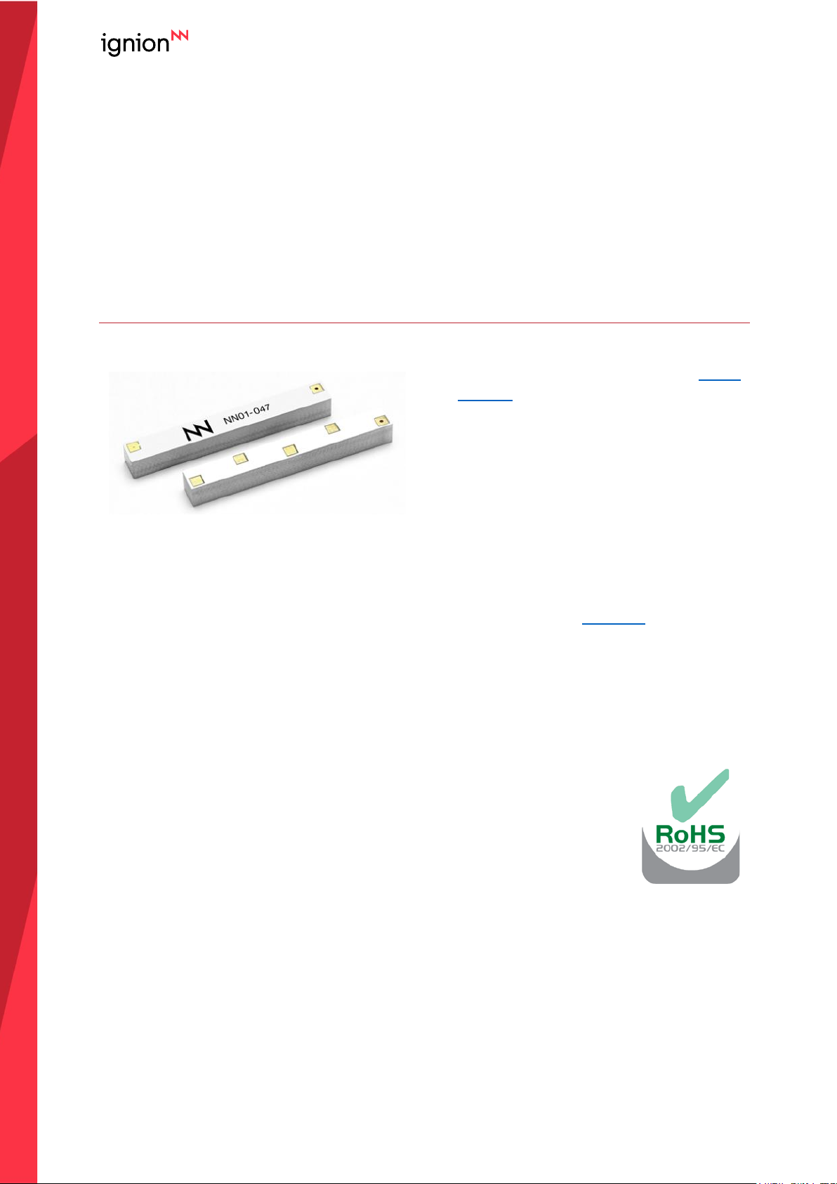
TVNowTM
NN01-047
Ignion products are protected by Ignion
patents.
All information contained within this
document is property of Ignion and is
subject to change without prior notice.
Information is provided “as is” and without
warranties. It is prohibited to copy or
reproduce this information without prior
approval.
Ignion is an ISO 9001:2015 certified
company. All our antennas are lead-free
and RoHS compliant.
ISO 9001: 2015 Certified
Page 3

3
Last Update: January 2021
USER MANUAL
TVNowTM (NN01-047)
INDEX OF CHAPTERS
1. ANTENNA DESCRIPTION 5
2. QUICK REFERENCE GUIDE 5
3. ELECTRICAL PERFORMANCE 6
4. MECHANICAL CHARACTERISTICS 10
5. ASSEMBLY PROCESS 12
6. PRODUCT CHANGE NOTIFICATION 14
Page 4

4
Last Update: January 2021
USER MANUAL
TVNowTM (NN01-047)
TABLE OF CONTENTS
1. ANTENNA DESCRIPTION 5
2. QUICK REFERENCE GUIDE 5
3. ELECTRICAL PERFORMANCE 6
3.1. EVALUATION BOARD 6
3.2. MATCHING NETWORK 7
3.3. RADIATION PATTERNS AND GAIN 8
3.4. CAPABILITIES AND MEASUREMENT SYSTEMS 9
4. MECHANICAL CHARACTERISTICS 10
4.1. DIMENSIONS AND TOLERANCES 10
4.2. SPECIFICATIONS FOR THE INK 10
4.3. ANTENNA FOOTPRINT 11
5. ASSEMBLY PROCESS 12
6. PRODUCT CHANGE NOTIFICATION 14
Page 5
5
Last Update: January 2021
USER MANUAL
TVNowTM (NN01-047)
1. ANTENNA DESCRIPTION
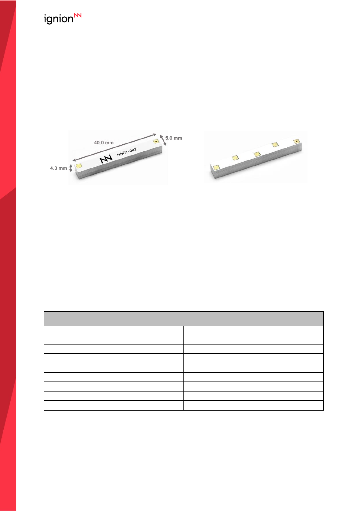
The TVNowTM is an off-the-shelf internal antenna solution specifically designed for DVB-H
applications, covering UHF and L-band requirements.
TVNowTM minimizes your product development cost and time. It combines small size and high
performance making TVNowTM an optimal choice for your portable DVB-H applications.
TOP
BOTTOM
Material: The TVNowTM antenna is built on glass epoxy substrate.
APPLICATIONS
▪ Mobile phones
▪ Personal Media Player (PMP)
▪ Ultra Mobile PC (UMPC)
▪ Secure Digital (SD) cards
BENEFITS
▪ Reduced Form Factor
▪ Modularity – SMD
▪ Superior Performance
▪ High Isolation (DVB-H and GSM)
2. QUICK REFERENCE GUIDE
Technical Features
Frequency Range with GSM Coexistence
470 – 698 MHz
1670 – 1675 MHz
Gain Curve
>2dBi margin with DVB-H recommendations
Radiation Pattern
Omnidirectional
Gain Flatness (horizontal diagram)
±2 dB
Weight (approx.)
1.9 g
Temperature
-40 to +125 ºC
Impedance
50 Ω
Dimensions (L x W x H)
40.0 mm x 5.0 mm x 4.8 mm
Table 1 – Technical Features. Measures from the evaluation board. See Figure 1.
Please contact [email protected] if you require additional information on antenna integration or
optimization on your PCB.
Page 6
6
Last Update: January 2021
USER MANUAL
TVNowTM (NN01-047)
3. ELECTRICAL PERFORMANCE
3.1. EVALUATION BOARD
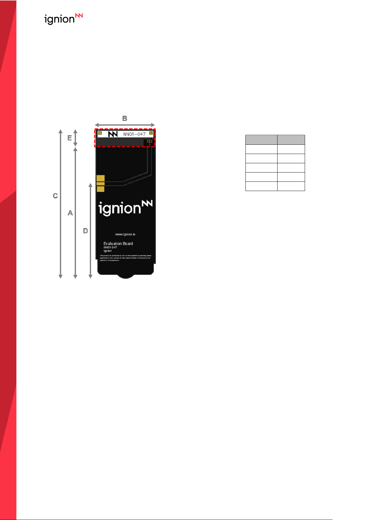
The configuration used in testing the TVNowTM Dual band (UHF+Lband) DVB-H antenna is
displayed in Figure 1.
Measure
mm
A
95.0
B
42.7
C
107.0
D
68.0
E
12.0
Tolerance: ±0.2mm
Material: The evaluation board is
built on laminated substrate 1.0
mm thick (2 layers).
Clearance Area: 12.0 mm x 42.7
mm (ExB)
Figure 1 – EB_NN01-047. TVNowTM Dual Band (UHF+Lband) DVB-H.
Page 7
7
Last Update: January 2021
USER MANUAL
TVNowTM (NN01-047)
3.2. MATCHING NETWORK
The specs of a Ignion standard antenna are measured in their evaluation board, which is an
ideal case. In a real design, components nearby the antenna, LCD’s, batteries, covers,
connectors, etc. affect the antenna performance. This is the reason why it is highly
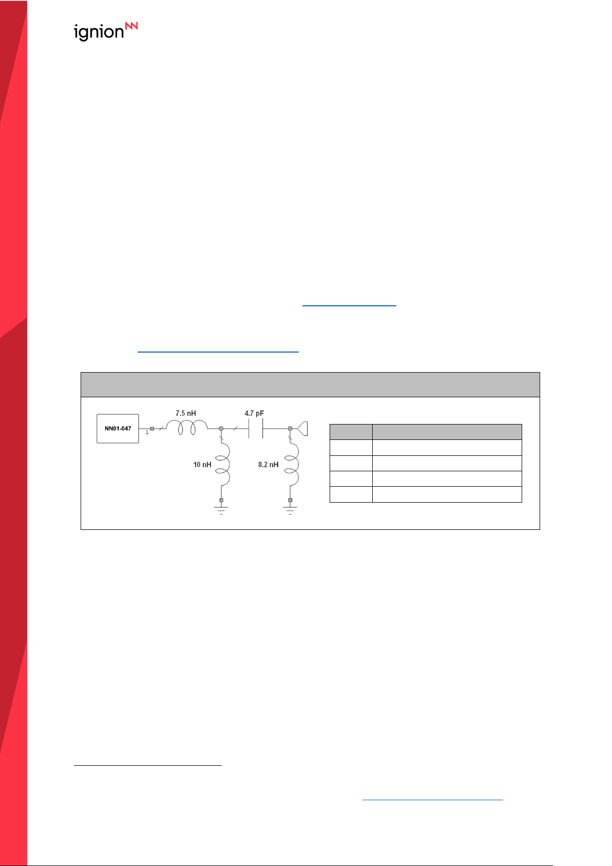
recommended placing pads compatible with 0402 and 0603 SMD components for a PI matching
network as close as possible to the antenna feeding point. Do it in the ground plane area, not in
the clearance area. This is a degree of freedom to tune the antenna once the design is finished
and considering all elements of the system (batteries, displays, covers, etc.).
Please notice that different devices with different ground planes and different components
nearby the TVNowTM Dual Band (UHF+Lband) DVB-H antenna may need a different matching
network. To ensure optimal results, the use of high Q and tight tolerance components is highly
recommended (Murata components). If you need assistance to design your matching network
beyond this application note, please contact [email protected], or try our free-of-charge1 NN
Wireless Fast-Track design service, you will get your chip antenna design including a custom
matching network for your device in 24h
1
. Other related to NN’s range of R&D services is
available at: https://www.ignion.io/rdservices/
Matching network for the Evaluation Board
Value
Part Number
7.5 nH
LQW15AN7N5H00
10 nH
LQW15AN10NG00
4.7 pF
GRM1555C1H4R7GZ01
8.2 nH
LQW15AN8N2G00
Figure 2 – Matching network implemented in the Evaluation Board.
1
See terms and conditions for a free NN Wireless Fast-Track service in 24h at: https://www.ignion.io/fast-track-project/
Page 8
8
Last Update: January 2021
USER MANUAL
TVNowTM (NN01-047)
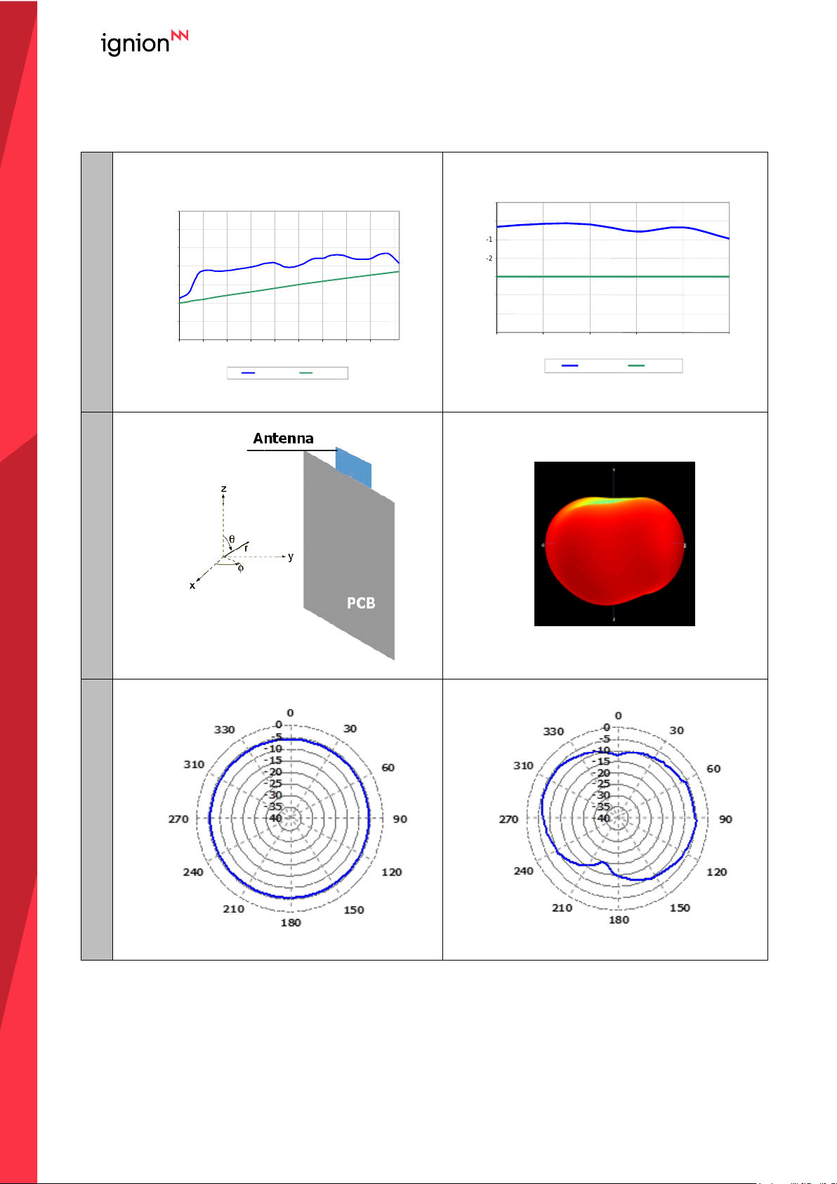
3.3. RADIATION PATTERNS AND GAIN
Table 2 – Typical antenna Gain across FM bandwidth.
GAIN
Radiation Pattern
Radiation Pattern
Gain
(dBi)
TVNow
TM
Performance Vs UHF DVB-H Specs
-14
-12
-10
-8
-6
-4
-2
0
470
495
520
545
570
595
620
645
670
695
Frequency (MHz)
Gain
ETSI Specs
TVnow
TM
performance in L US bands
-6
-5
-4
-3
-2
-1
0
1
1660
1665
1670
1675
1680
1685
frequency (MHz)
Gain
Gain
ETSI Specs
Page 9
9
Last Update: January 2021
USER MANUAL
TVNowTM (NN01-047)
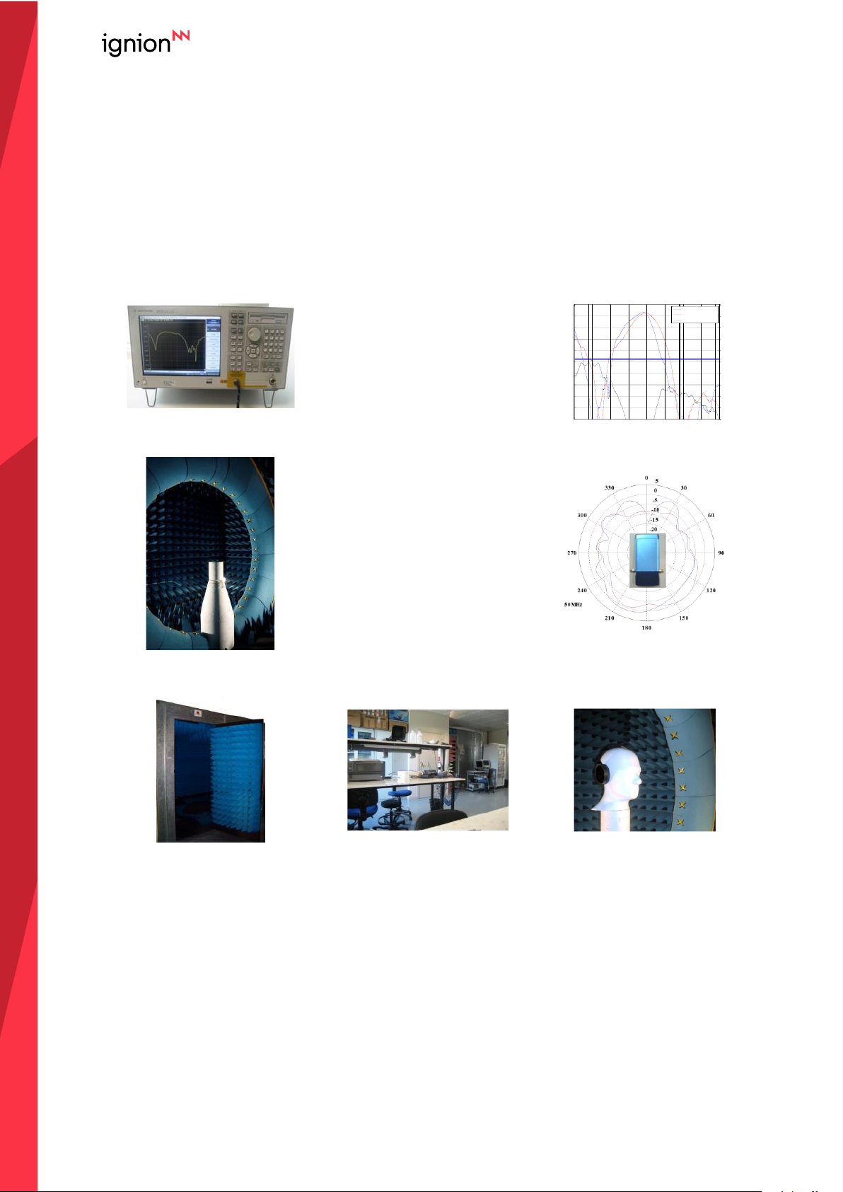
3.4. CAPABILITIES AND MEASUREMENT SYSTEMS
Ignion specializes in the design and manufacture of optimized antennas for wireless
applications, and with the provision of RF expertise to a wide range of clients. We offer turn-key
antenna products and antenna integration support to minimize your time requirements and
maximize return on investment throughout the product development process. We also provide
our clients with the opportunity to leverage our in-house testing and measurement facilities to
obtain accurate results quickly and efficiently.
Agilent E5071B
VSWR
&
S Parameters
Radiation
Pattern
&
Efficiency
SATIMO STARGATE 32
Anechoic chambers and full equipped in-house lab
2 2.5 3 3.5 4 4.5 5 5 .5 6
-20
-18
-16
-14
-12
-10
-8
-6
-4
-2
0
Return Lo ss (dB)
Frequ ency (GHz)
Left Ante nna
Right An tenna
Isola tion
VSWR=2
2 2.5 3 3.5 4 4.5 5 5 .5 6
-20
-18
-16
-14
-12
-10
-8
-6
-4
-2
0
Return Lo ss (dB)
Frequ ency (GHz)
Left Ante nna
Right An tenna
Isola tion
VSWR=2
Page 10
10
Last Update: January 2021
USER MANUAL
TVNowTM (NN01-047)
4. MECHANICAL CHARACTERISTICS
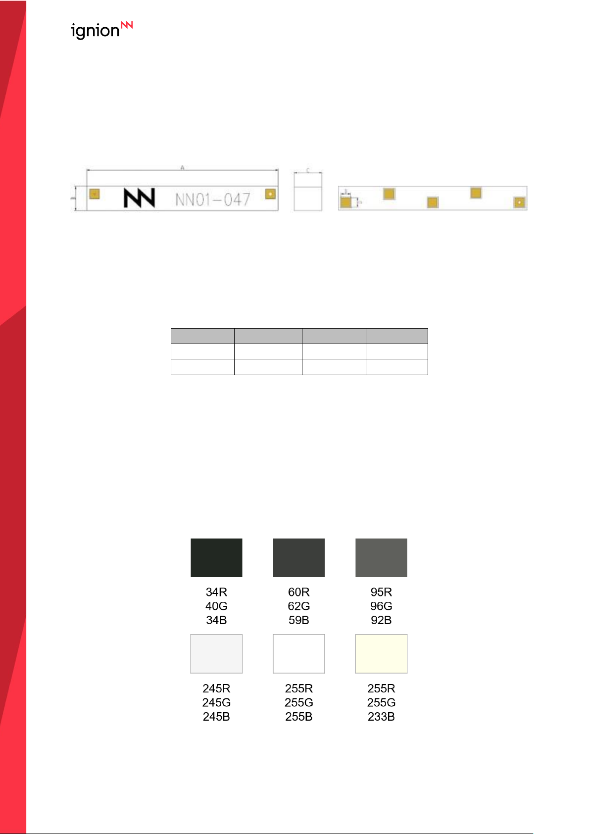
4.1. DIMENSIONS AND TOLERANCES
TOP
SIDE
BOTTOM
Note: all antenna pads (feed point and mounting pads) have the same dimensions
The yellow hole on the front of the antenna provides a visual cue to mounting the antenna. It is
located above the feed point of the antenna and is included to decrease possible manufacturing
error.
Measure
mm
Measure
mm
A
40.0 0.2
C
4.8 0.2
B
5.0 0.2
D
2.0 0.1
Figure 3 – Antenna Dimensions and Tolerances.
The TVNowTM Dual Band (UHF+Lband) DVB-H antenna is compliant with the restriction of the
use of hazardous substances (RoHS).
4.2. SPECIFICATIONS FOR THE INK
Next figure shows the correct colors of the antenna:
Acceptable color range
Page 11
11
Last Update: January 2021
USER MANUAL
TVNowTM (NN01-047)
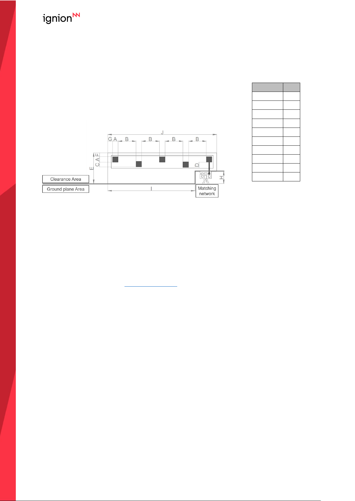
4.3. ANTENNA FOOTPRINT
This antenna footprint applies for the reference evaluation board described on page 6 of this
User Manual.
Measure
mm
A
2.0 B 7.0
C
1.8
D
2.0
E
12.0
F
1.5 G 1.9
H
4.7
I
34.2
J
42.7
Tolerance: ±0.2 mm
Note: all the soldering pads
(feed point and mounting
pads) on the antenna layout
have the same dimensions.
Figure 4 – Antenna Footprint Details.
Other PCB form factors and configurations may require a different feeding configuration, feeding
line dimensions and clearance areas. If you require support for the integration of the antenna in
your design, please contact [email protected]
Page 12
12
Last Update: January 2021
USER MANUAL
TVNowTM (NN01-047)
5. ASSEMBLY PROCESS
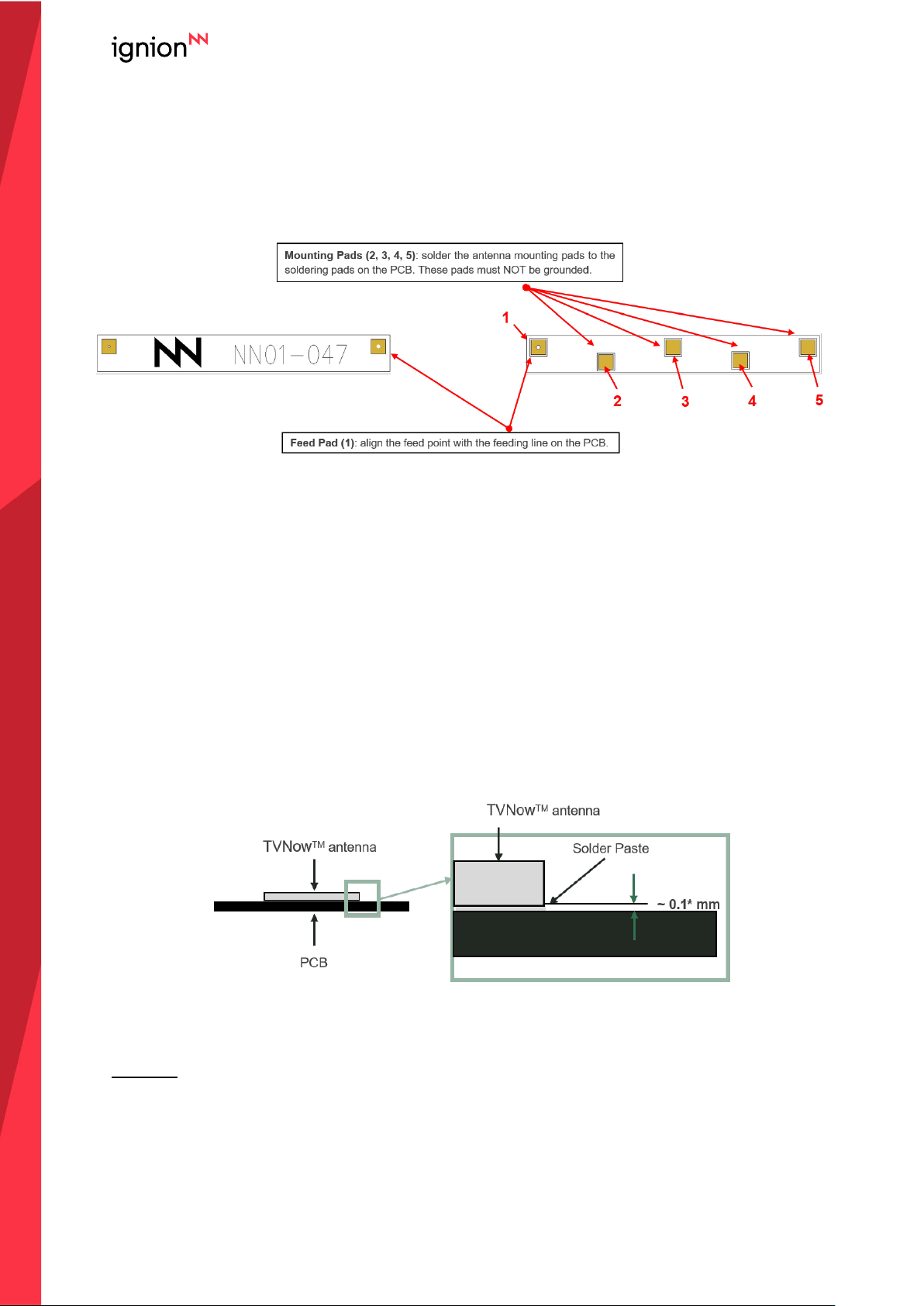
Figure 5 shows the back and front view of the TVNowTM antenna, and indicates the location of
the feeding point and the mounting pads:
Figure 5 – Views of the TVNowTM Dual band (UHF+Lband) DVB-H antenna.
As a surface mount device (SMD), this antenna is compatible with industry standard soldering
processes. The basic assembly procedure for this antenna is as follows:
1. Apply a solder paste to the pads of the PCB. Place the antenna on the board.
2. Perform a reflow process according to the temperature profile detailed in Table 3, Figure 7
on page 13.
3. After soldering the antenna to the circuit board, perform a cleaning process to remove any
residual flux. Ignion recommends conducting a visual inspection after the cleaning process
to verify that all reflux has been removed.
The drawing below shows the soldering details obtained after a correct assembly process:
Figure 6 – Soldering Details.
NOTE(*): Solder paste thickness after the assembly process will depend on the thickness of the
soldering stencil mask. A stencil thickness equal to or larger than 127 microns (5 mils) is
required.
Page 13
13
Last Update: January 2021
USER MANUAL
TVNowTM (NN01-047)
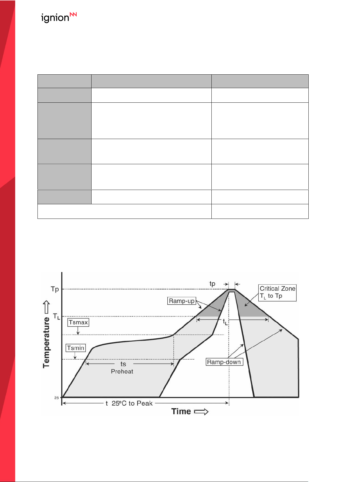
The TVNowTM antenna should be assembled following either Sn-Pb or Pb-free assembly
processes. According to the Standard IPC/JEDEC J-STD-020C, the temperature profile
suggested is as follows:
Phase
Profile features
Pb-Free Assembly (SnAgCu)
RAMP-UP
Avg. Ramp-up Rate (Tsmax to Tp)
3 ºC / second (max.)
PREHEAT
- Temperature Min (Tsmin)
- Temperature Max (Tsmax)
- Time (tsmin to tsmax)
150 ºC
200 ºC
60-180 seconds
REFLOW
- Temperature (TL)
- Total Time above TL (tL)
217 ºC
60-150 seconds
PEAK
- Temperature (Tp)
- Time (tp)
260 ºC
20-40 seconds
RAMP-DOWN
Rate
6 ºC/second max
Time from 25 ºC to Peak Temperature
8 minutes max
Table 3 – Recommended soldering temperatures.
Next graphic shows temperature profile (grey zone) for the antenna assembly process in reflow
ovens.
Figure 7 – Temperature profile.
Page 14
14
Last Update: January 2021
USER MANUAL
TVNowTM (NN01-047)
6. PRODUCT CHANGE NOTIFICATION
This document is property of Ignion,
Not to disclose or copy without prior written consent
PCN Number: NN19100007
Notification Date: October 07th, 2019
Part Number identification:
Part Number changes, it will be applied in all the document of the company (User Manual,
Data Sheet, …)
Previous Part
Number
New Part Number
FR01-B1-S-0-047
NN01-047
Reason for change:
Specs (electrical/mechanical)
Manufacturing location
User Manual/Data Sheet
Quality/Reliability
Material/Composition
Logistics
Processing/Manufacturing
X
Other: Logo, product color and Part
Number
Change description
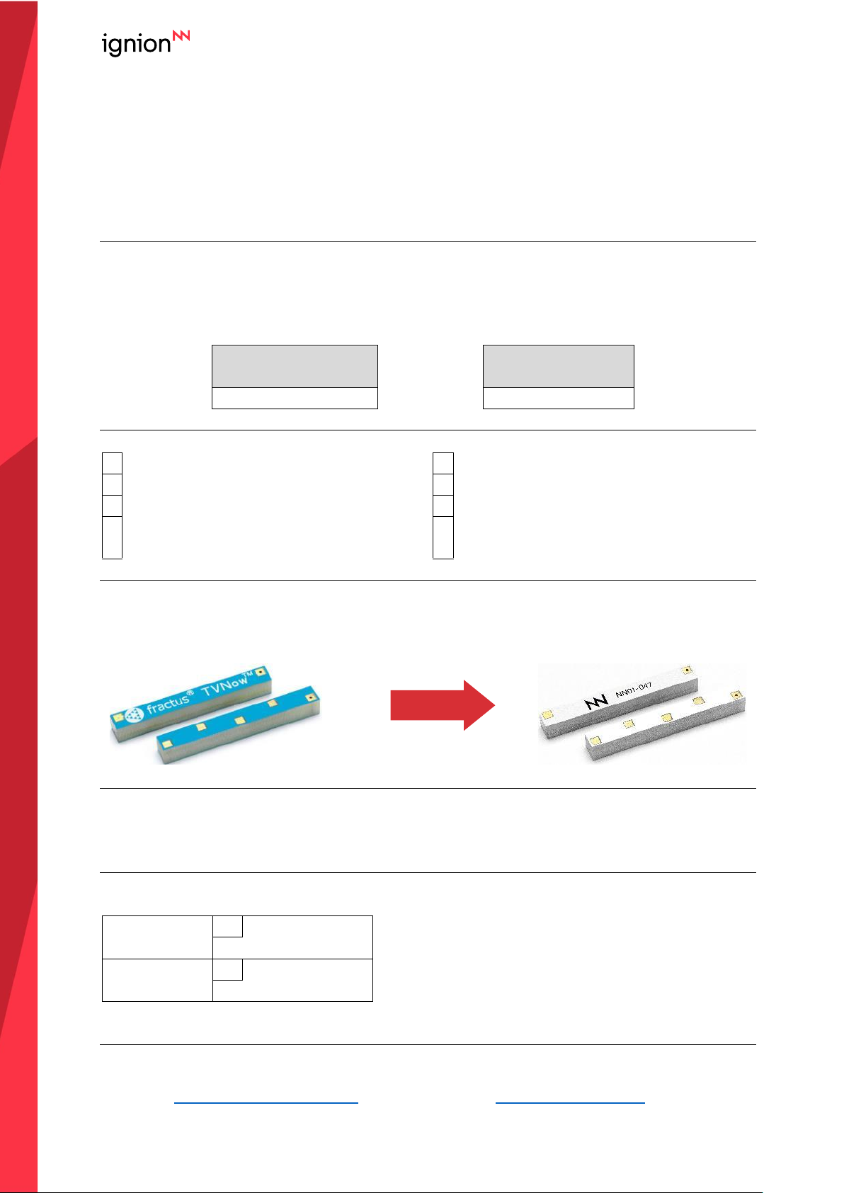
1.- Part Number: From FR01-B1-S-0-047 FRACTUS to NN01-047 Ignion in the User Manual
2.- Color: From blue/white to white/black
OLD
NEW
Comments:
1.- Electrical and Mechanical specs remain the same
2.- Footprint in the PCB to solder the chip antenna remains the same
Identification method
1.- In the chip antennas, the changes are in the color, in the logo and in the part number
User Manual
X
Available from:
February 2020
Samples
X
Available from:
January 2020
Ignion Contact:
Sales
Supply Chain
Name:
Josep Portabella
Albert Vidal
Email:
Page 15

15
Last Update: January 2021
USER MANUAL
TVNowTM (NN01-047)
Barcelona
Av. Alcalde Barnils, 64-68 Modul C, 3a pl.
Sant Cugat del Vallés
08174 Barcelona
Spain
Shanghai
Shanghai Bund Centre
18/F Bund Centre, 222 Yan’an Road East,
Huangpu District
Shanghai, 200002
China
New Dehli
New Delhi, Red Fort Capital Parsvnath Towers
Bhai Veer Singh Marg, Gole Market,
New Delhi, 110001
India
Tampa
8875 Hidden River Parkway
Suite 300
Tampa, FL 33637
USA
Page 16

Mouser Electronics
Authorized Distributor
Click to View Pricing, Inventory, Delivery & Lifecycle Information:
Ignion:
EB_NN01-047
 Loading...