

Page 1
y
y
y
y
g
y
g
F
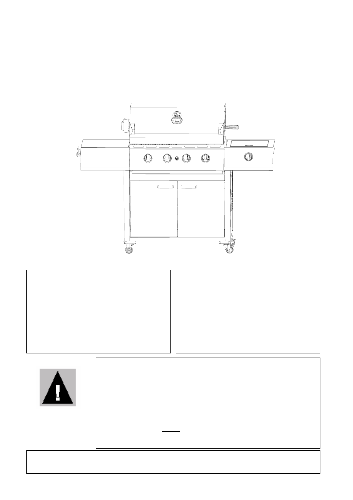
IGW 400 - 4 BURNER STAINLESS STEEL GAS GRILL (BB10514A)
ASSEMBLY AND OPERATING INSTRUCTIONS
Igloo® is a trademark of Igloo Products Corp. Registered in the United States Patent and Trademark Office. All Rights Reserved.
If you smell gas:
1. Shut off gas to the appliance.
2. Extinguish any open flame.
3. Open hood.
4. If odor continues, immediatel
FOR YOUR SAFETY
our gas supplier or your fire
department.
z For outdoor use only. Not for commercial use.
z Read instructions before usin
follow instructions could result in death, serious bodil
injury, and/or property loss.
z Warnin
children away.
z Do not move the appliance during use.
FOR YOUR SAFETY
1. Do not store or use gasoline or
other flammable vapors or liquids
in the vicinit
appliance.
call
2. An LP cylinder not connected for
use shall not be stored in the
vicinit
of this or any other
appliance.
: accessible parts may be very hot. Keep young
of this or any other
the appliance. Failure to
50,000 BTUs with
10,000 BTUs Side Burner
z Turn off the gas supply at the gas cylinder after use.
WARNING
z CONTACT 1-866-NAO-GRILL (1-866-626-4745) FOR ASSISTANCE
z DO NOT RETURN TO PLACE O
z Any modification of the appliance may be dangerous.
z This grill can
NOT be converted to natural gas.
z Installer to leave instructions with the consumer and
consumer to retain them for future re ference.
PURCHASE
1
Page 2

WARNINGS
PLEASE READ THESE INSTRUCTIONS CAREFULLY BEFORE ASSEMBLY AND USE.
FAILURE TO FOLLOW THESE INSTRUCTIONS COULD RESULT IN DEATH, SERIOUS
BODILY INJURY, AND/OR PROPERTY LOSS. READ AND FOLLOW ALL INSTRUCTIONS
CAREFULLY BEFORE ASSEMBLY OR USE OF THIS OUTDOOR GAS GRILL.
*WARNING! Read and follow all instructions. Retain these instructions for future reference.
z Installation must conform with local codes, or in the absence of local codes, with either the National
Fuel Gas Code, ANSI Z223.1/NFPA 54, or CAN/CGA-B149.1, Natural Gas and Propane
Installation code.
z This outdoor gas grill is for use only outdoors. DO NOT use inside a building, garage, or any other
enclosed area.
z This outdoor gas grill is not intended to be installed in or on recreational vehicles and/or boats.
z This outdoor gas grill should not be located under overhead combustible construction and proper
clearances must be maintained at all times from combustible construction and/or materials, with
MINIMUM clearances as follows:
From Sides – 24 in. (61 cm)
From back – 24 in. (61 cm)
z Place in a well-ventilated area.
z Inspect the hose before each use. If there is evidence of excessive abrasion or wear, or the hose is
cut, do not operate grill. Use only the pressure regulator and hose supplied with this grill.
Contact Customer Service for assistance - 1-866-626-4745 or
z *WARNING! If your outdoor gas grill catches on fire, use an ABC fire extinguisher to extinguish
the fire. Never attempt to extinguish a grease fire with water or other liquids. Turn off all control
knobs on outdoor gas grill and LP cylinder valve if they can be reached safely. If you cannot safely
reach the control knobs or LP cylinder valve to stop the flow of gas that can feed the fire, evacuate
the area and call the fire department
z This gas grill is not designed to be used with natural gas. Conversion to natural gas should NOT be
attempted as it will create an unsafe situation.
z This gas grill should not be connected to any gas supply other than a Type 1 compatible propane gas
cylinder. Connection to home gas lines will result in poor performance of the grill and may result
in an unsafe condition.
z Any LP gas supply cylinder used with this grill must be approximately 12 in. (30.5 cm) diameter
and 18 in. (45.7 cm) high. The maximum fuel capacity is 80 percent and is approximately 20
pounds (9 kg) of propane. The maximum weight of a properly filled cylinder is approximately 38
pounds (17.2 kg)<47.7 lbs. (21.6kg) nominal water capacity>. The LP cylinder must have a shut-off
valve terminating in a Type 1 LP gas cylinder valve outlet.
z Any LP gas cylinder used with this gas grill must be constructed and marked in accordance with the
specifications for LP gas cylinders of the U.S. Department of Transportation (DOT) or the National
Standard of Canada, CAN/CSA-B339, Cylinder, Spheres and Tubes for Transportation of
Dangerous Goods; and Commission, as appliance; and must be provided with a listed overfilling
prevention device.
z The LP gas cylinder must be a Type 1 compatible cylinder with a Type 1 cylinder valve that has a
back-check valve, which does not permit gas flow, until a positive seal has been obtained.
www.americancustomerservice.com.
2
Page 3

z The cylinder must be arranged for vapor withdrawal. It must also include a collar to protect the
cylinder valve. A safety relief device having direct communication with the vapor space of
cylinder must be provided. This will expel high-pressure gas if the cylinder is overfilled or
overheated which could result in fire or explosion.
z The gas must be turned off at the cylinder when the outdoor gas grill is not in use.
z Do not store this gas grill indoors unless cylinder is disconnected and removed from the appliance.
z Cylinders must always be stored outdoors out of the reach of children and must not be stored in a
building, garage, or any other enclosed area.
*WARNING! Do not store a spare LP gas cylinder under or near this appliance. Never fill the cylinder
beyond 80 percent full. If these installation
s instructions are not followed exactly, a fire causing death or
serious injury may occur.
z Never use this gas grill without the drip pan in place.
z *WARNING! If you see grease or other hot material dripping from the grill onto valve, hose or
regulator, turn off gas supply immediately. After the grill has cooled, determine the source and
correct it.
z Check the LP gas grill for gas leaks and burner obstructions before each use. *WARNING! Do not
use a flame to check for gas leaks. See
Leak T est Instruction section of this manual for correct
leak test procedures. A clogged burner tube can cause a fire inside or beneath the grill.
z *DANGER! If you see, smell, or hear, escaping gas from the LP cylinder, evacuate the area
and call the fire department.
z *WARNING! Never light the gas grill before lifting the lid, to prevent an explosion from gas
build-up.
z Exercise care when using this gas cooking appliance. Never leave gas grill unattended during
operation or cleaning.
z Never allow children to operate or play near this or any gas grill.
z *WARNING! Do not move a gas grill when in operation or hot.
z *WARNING! Never touch hot surfaces. Use heat resistant gloves. The gas grill will become
very hot.
z Use of this gas grill other than for the intended use, or alteration of gas grill in any way may not be
safe, and could result in death, serious bodily injury and/or property loss.
z Never attempt to repair the gas grill or LP cylinder yourself. Contact the manufacturer for
information regarding repairs to your gas grill. Contact your local Liquefied Petroleum supplier
for information regarding repairs to you LP gas cylinder.
z *WARNING! Do not use aerosols or store flammable liquids or materials near this gas grill.
z *WARNING! Do not wear loose clothing around any gas grill while in use or hot.
z Never store an LP gas cylinder indoors (empty or filled). If storing the gas grill indoors,
disconnect the LP gas cylinder and store it outdoors, out of the reach of children.
z Never leave an LP cylinder inside a vehicle, which may become overheated by the sun.
z Do not attempt to disconnect any gas fitting while your gas grill is in operation.
z Your gas grill should be cleaned regularly.
z This gas grill should never be used with more than 50% of the cooking area as a solid plate (griddle).
Full coverage of plates will cause excessive heat and could damage the grill.
z Any alteration to the design of the grill will void any and all warranties and may result in an unsafe
condition.
3
Page 4
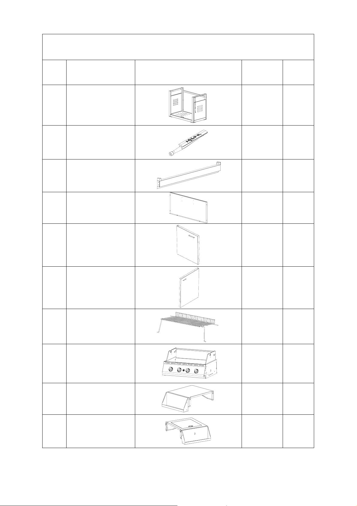
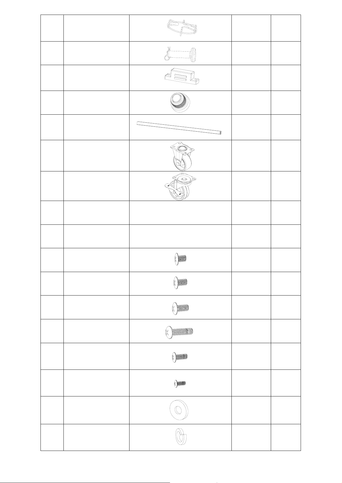
Parts List For Grill -- BB10514A
For parts please call us at 1-866-626-4745 M-F, 8:30am to 5:30pm EST
ITEM DESCRIPTION
1
2
3
4
Frame
--preassembled
Brass Burners
--preassembled
Cross Support
Back Panel
PART
Replacement
Part #
G200
G233 4
G202 1
G203 1
QTY
INCLUDED
1
5
6
7
8
9
Left Door
Right Door
Warming Rack
Body
Left Shelf
G204 1
G205
G206 1
G207
Not
Replaceable
G208 1
1
1
10
Right Shelf
G209 1
4
Page 5
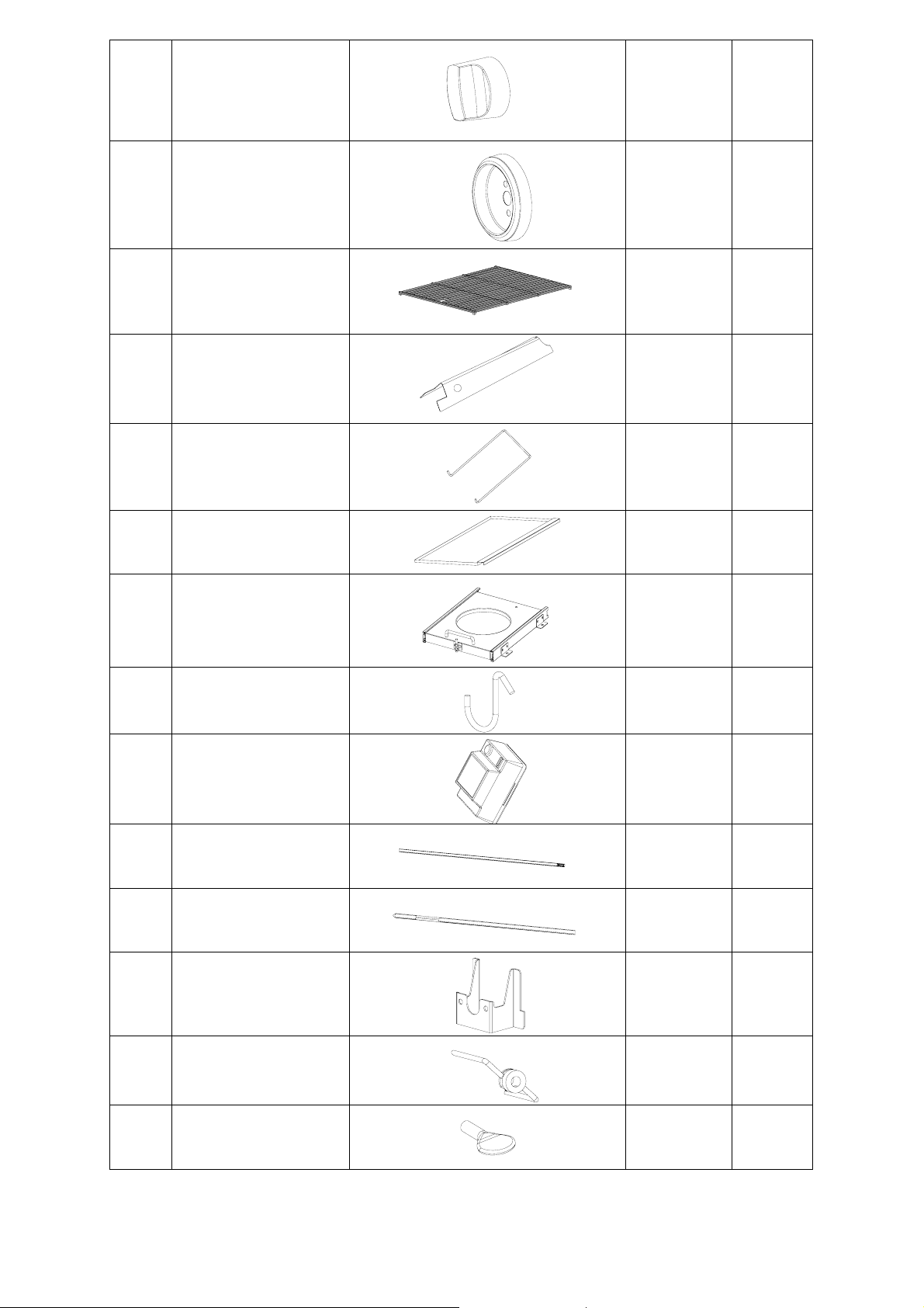
11
Side burner knob
G128 1
12
13
14
15
16
17
Knob base
Cooking Grids
Flame Diffusers
Cylinder lock line
Drip pan
Cylinder Support
G129 1
G210 2
G211 4
G127 1
G212 1
G213 1
18
19
20
22
23
21
S Hooks
Rotisserie Motor
Motor Pole A
(Handle Side)
Motor Pole B
(Motor Side)
Motor Support
Forks
G214 5
G215 1
G216 1
G217 1
G218 1
G219 2
24
Wing Nut / Thumb
Screws--preassembled
G220 3
5
Page 6
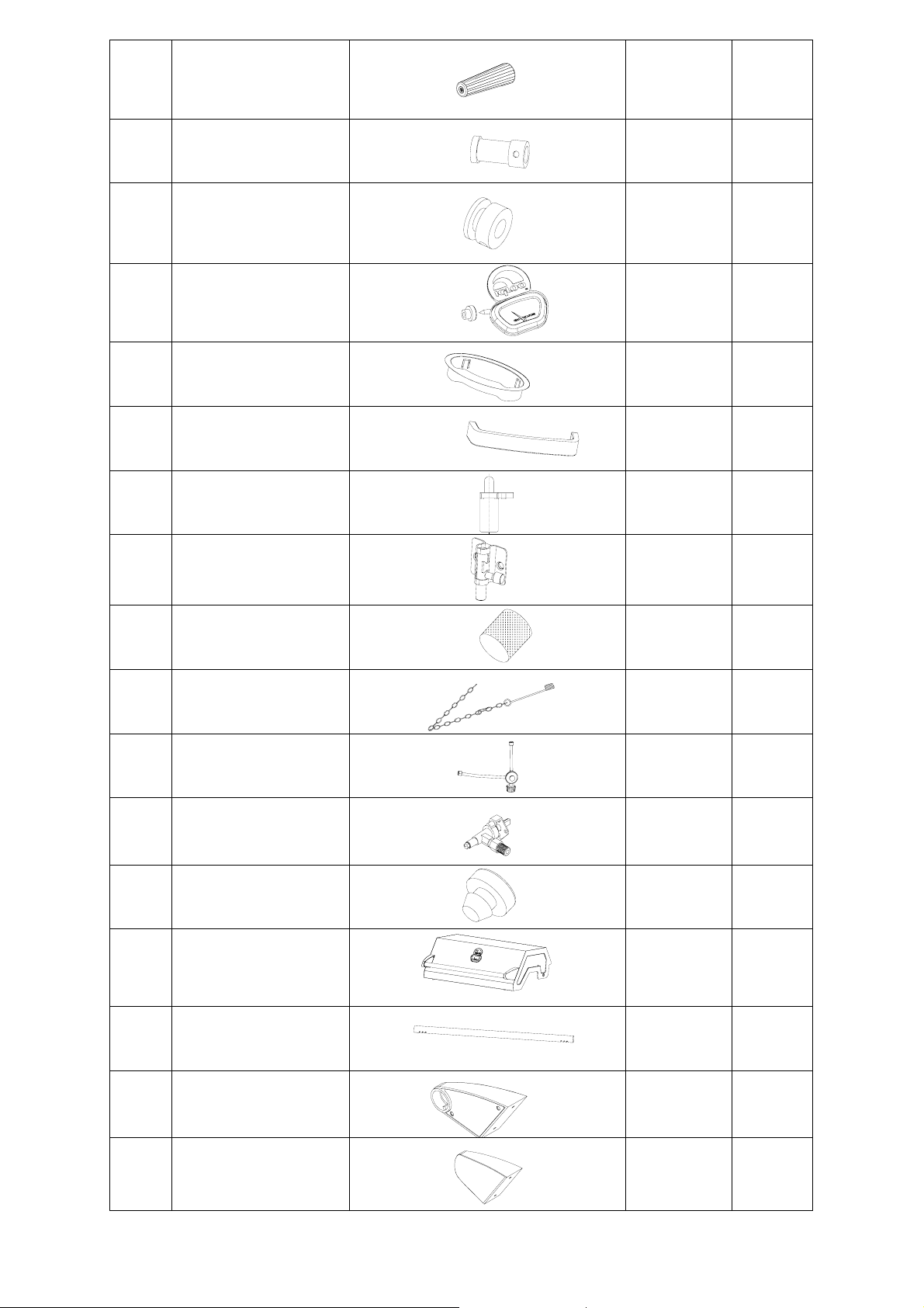
25
Motor Pole Handle
(Plastic)
--preassembled
G221 1
26
27
28
29
30
31
32
Motor Pole Coupling
--preassembled
Pole Restrictor
--preassembled
Snap-In Thermostat
--preassembled
Side Shelf Handle -preassembled
Door Handle –
preassembled
Door Spring Latch
--preassembled
Tank Support Shelf
Lock --preassembled
G222 1
G223 1
G130 1
G131 1
G132 2
G133 2
G134 1
33
34
35
36
37
38
39
Burner Insect Cover
--preassembled
Match Holder with
chain - preassembled
Dual Regulator and
Hose - preassembled
Side Burner Valve
–preassembled
Rubber Bumper (lid)
--preassembled
Hood --preassembled
Hood Handle
--preassembled
G135 5
G136 1
G224 1
G225 1
H11A 2
G226 1
G227 1
40
41
Hood Handle Bracket
(Left) --preassembled
Hood Handle Bracket
(Right) --preassembled
G228 1
G229 1
6
Page 7
42
Side Burner Trivet
--preassembled
G230 1
43
44
45
46
47
48
Hood Pin & Cotter Pin
--preassembled
Door Magnet w/
screws --preassembled
Igniter Cover
--preassembled
Rear Cross Support w/
screws --preassembled
Fixed Castors
Swivel Castors
G231 2
G140 4
G141 1
G232 1
G201 2
G234 2
A M6x10 Bolts
B M6x12 Bolts
C M6x16 Bolts
D M6x20 Bolts
E M5X12 Bolts
F M4X8 Bolts
Hardware Pack
H240 1
H610 2
H612 4
H616 35
H620 4
H512 2
H651
2
G D6 Washers
H D6 Spring Washers
H416 29
H426 19
7
Page 8
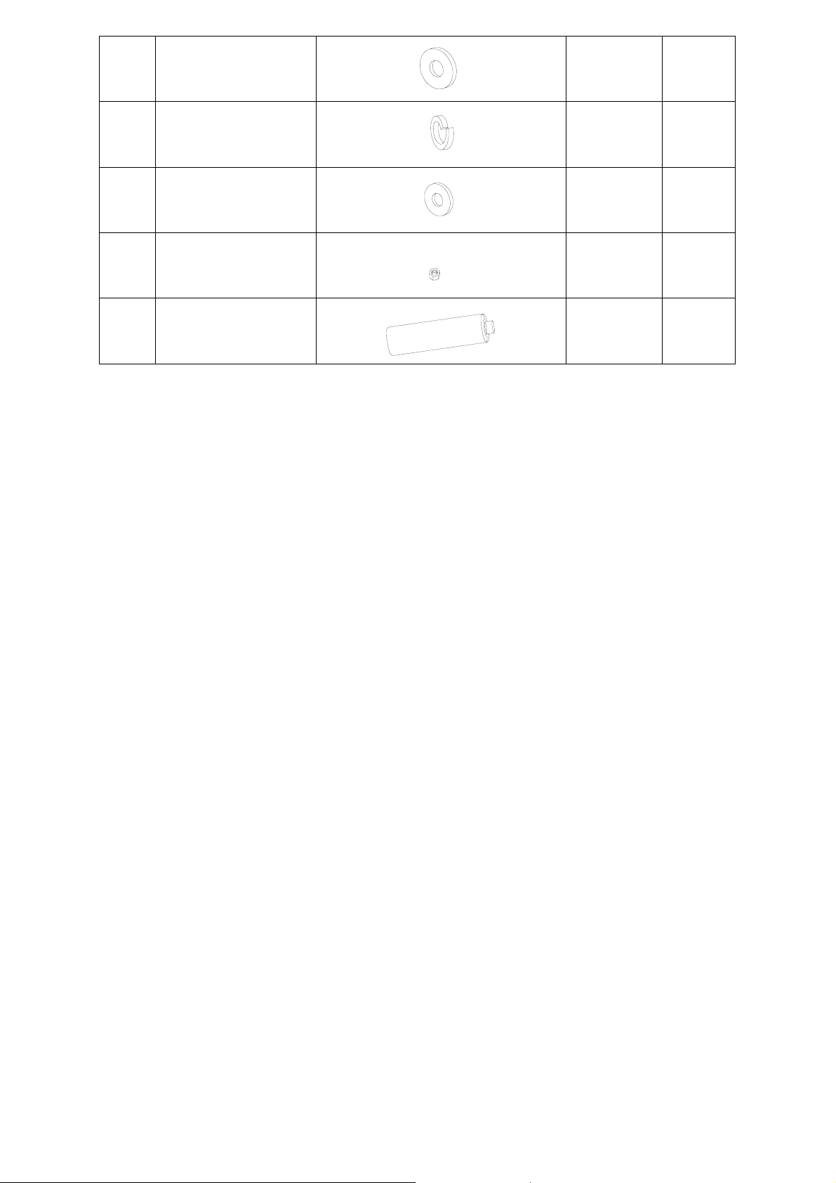
I D5 Washers
H415 2
J D5 Spring Washers
K D4 Washers
L M5 Nuts
M Battery
ASSEMBLY INSTRUCTIONS
Before You Start
H425 2
H411 2
H515 2
H011 1
z When you are ready to start, make sure that you have the right tools at hand, plenty of space and a
clean dry area for assembly.
Assembly – Note: Two People Required for Assembly
z Using knife or box cutter, cut open carton.
z Lay out all bolts and check lengths before assembly. It is recommended that the carton is cut open
and spread out on the floor and used as a protective surface during assembly. Refer to the assembly
diagrams as necessary.
z Remove all packaged parts from the inside of the grill body before assembling.
z
This product is for OUTDOOR USE ONLY.
z
NEVER use indoor, in an enclosed area or below ground level.
z
NEVER use an adjustable regulator with this grill. Use only the pressure regulator and hose
supplied.
8
Page 9

STEP – 1:
Unpack and inspect all parts listed. If you
believe you have missing parts, please
check all boxes parts of the grill. Some
parts are shipped in place or pre-assem bled.
If you have damaged or missing parts, do
not return to the store. Please contact
American Customer Service toll free at
1-866-626-4745 or visit us on the web at
www.americancustomerservice.com.
Please have your model number
(BB10514A) and the Replaceable Part #
available.
48
C
A
H
47
G
1
STEP – 2:
Turn Frame (1) up-side down, screw Fixed
Castor (47) into frame (1) using six Bolts (C),
two Bolts (A), eight Spring Washers (H), and
eight Washers (G), as shown..
Screw Swivel Castor (48) into frame (1) using
C
seven Bolts (C), seven Spring Washers (H), and
seven Washers (G), as shown.
Please lock all casters before continuing with
assembly.
Note : had to increase size of drawing
so the hardware parts are visible.
Also we changed your wording on #of
pieces so it is not confusing to the
consumer.
9
Page 10

1
C
4
G
STEP – 3:
Attach Back Panel (4) to Frame (1) with
Bolts (C), Washers (G), as shown.
1
17
C
STEP – 4:
Attach Cylinder Support (17) to frame
(1) with Bolts (C), as shown.
H
C
G
3
1
STEP – 5:
Attach Cross Support (3) to Frame (1)
with Bolts (C), Spring Washers (H)
and Washers (G), as shown.
Note: The two “tabs” of the Cross
Support (3) will be oriented UP for
assembly.
10
Page 11

b
46 Rear Cross Support
STEP – 6:
Fit the Doors (5) & (6) into Frame (1) in the
positions show by first inserting the post on
the bottom corner of the door into the hole on
the bottom of the Frame (1) and then while
pressing down on to the Door Spring Latch
(31), move the door into position as shown.
Tighten the screws that attach the Rear Cross
5
6
Support (46) which is pre-assembled.
G
D
8
1
STEP -7:
REQUIRES TW
Prior to placing body onto fram
secure the side burner ignition wire to the
ottom of the body with tape to prevent the
wire from being cut during assembly.
Be sure to wear thick protective gloves to
prevent possible injury during this step of
assembly.
Place Bod
Support (3) & Rear Cross Support (45).
Line up with bottom two bolt hoes on the
body and attach using four Bolts (D) and four
Flat Washers (G).
Note: Remove any ca
the hose assembly. Be sure the Hose
Assembly (35) is under the Body (8) and
inside the Frame (1) before attaching bolts.
The Hose Assembly (35) should NOT hang
O PEOPLE
e, temporarily
y (8) onto Frame (1) & Cross
ble ties carefully from
11
Page 12

b
b
8
C
10
9
B
STEP – 8:
a. Remove two
grill. (These bolts
attach the FRONT PANEL to the body.)
b. Partially screw two bolts (C) to the Body
(8) at the top, as shown.
c. Fit shelf onto the two bolts (A) that are
partially attached, as sh
ottom of the shelf with two more Bolts (A).
d. Re-install the two bolts you removed from
the FRONT PANEL.
REPEAT STEPS for other shelf.
Tighten all bolts.
bolts from the side of the
are the two bolts that
own, and attach the
STEP - 9:
m the pre-assembled side Remove screws fro
urner, as shown. (Retain these screws for use
later in assembly.)
12
Page 13

36
hose
10
Fig. 10.1
Sid alve
e Burner V
Burner Pipe
Igniter T erm inal
Igniter wire
STEP – 10:
a. Thread the
the hole p
Burner Shelf (10), as shown in Fig. 10.1.
b.
Using the screw (F) and washer (K),
install the Knob Base (12) into the Right
Side Shelf (10) and then into the Side
Burner Valve frame (36). Tighten
securely, as shown in Fig. 10.3.
c.
Slide burner pipe over valve, as shown
in Fig. 10.2.
d. Fit Side Burner Knob (11) onto valve, as
shown in Fig.
e. Fit igniter wire to the igniter terminal, as
shown in figure 10.2
f. Reinstall screws into Side Burner as
shown in STEP 9.
Side Burner Valve (36) into
rovided on the Right Side
10.3
.
11
12
Fig. 10.2
F,K
Fig. 10.3
13
Page 14

STEP – 11:
Remove Drip Pam (16) from Grill
Body (8). Remove any packing
material and then slide back into grill
16
as shown.
21
E
L
J
I
STEP – 12 :
Mount Motor Support (21) to the Grill
Body (8) with two Bolts (E), two
Washers (I), two Spring Washers (J), &
two Nuts (L), as shown. Tighten
securely.
NOTE: The Motor Mount must be
installed
opposite of the Side Burner.
13
14
8
STEP – 13 :
Place the Flame Diffusers (14) over the
Burners (2) with the notch to the front edge
of the burners.
Place the Cooking Grids (13) into the Body
(8), as shown.
Note: Be sure to follow directions for
seasoning grids under the GETTING
STARTED section of your manual before
use.
14 15
Page 15

8
STEP – 14 :
7
Install Warming Rack (7) by inserting
the extensions into the holes under the
M
Fig. 14.1
Motor Support (22) and into the ho les
on the Hood (38), as shown in Fig.
14.1.
Un-screw the Igniter Cover (45), insert
the Battery (M), and replace the Igniter
Cover (45), as shown in Fig. 14.2.
Note: The negative “-“ pole of the
Battery (k) should be inserted first.
Fig. 14.2
STEP – 15:
Pull out Cylinder Support (17).
Install Cylinder Lock Line (15) into the
surface holes of the Cylinder Support
(17), as shown.
15
Page 16

STEP – 16:
Install the cylinder (not included) on the
cylinder support as shown and slide into the
frame.
Secure the cylinder lock line onto the surface
of the cylinder as show.
Slowly push cylinder support into frame
Note: Ensure the grill is on level ground
before you place the cylinder.
Note: Lock the casters before lighting this
grill.
STEP – 17:
Note: The cylinder support must be
locked in place before use.
18
9
STEP – 18:
Install “S” Hooks (18) into the holes
on the outside of the Left Shelf (9), as
shown.
16
Page 17

Rotisserie Assembly
19
23
Assembling the Motor Pole (Spit)
25
1. Identify the Motor Pole A (20) and
Motor Pole B (21).
2. Slide one Fork (23) onto Motor Pole A
27
Note: Restrictor Screw should be oriented
TOWARDS the Handle (25), as shown
(20), as shown.
3. Attach Motor Pole Coupling (26) to
Motor Pole A (20).
4. Attach Motor Pole B (21) to Motor Pole
Coupling (26).
5. Slide remaining Fork (23) onto Motor
Pole B (21), as shown.
6. Remove plastic covers from forks
before use.
24
21
26
20
IMPORTANT: Before installing Rotisserie, you must remove the Warming Rack (7). DO NOT leave
Rotisserie Motor (19) on the grill during when not in use.
1. Install Motor (19) by sliding it down onto the Motor Support (21).
2. Insert the pointed end of the Motor Pole assembly into the crank housing of the Motor (19), as
shown.
3. Rest the handle side of the rotisserie in the grove of the Grill Body (8), as shown.
Note: The Pole Restrictor (27) must be adjusted so that it rests in the grove of the grill body. The
Wing Nut (24) should be OUTSIDE the Grill Body (8), as shown.
Using Rotisserie
17
Page 18

MAIN BURNER AND SIDE BURNER WITH RESPECT TO PROPER
LOCATION: WARNING – ALWAYS CHECK TO ENSURE BURNERS ARE
POSITIONED CORRECTLY BEFORE EACH USE
Valve
Burner
Main valve orifice with burner properly positioned Side valve orifice with burner properly positioned
[Internal connection] [Internal connection]
Valve
Burner pipe
CONNECTING THE GAS
Connecting to a Gas Cylinder
1. Ensure all control knobs are in the OFF position and verify that the LP gas cylinder valve is closed by turning the
handle on the LP gas cylinder valve clockwise until it stops.
2. Remove the protective cap from the LP cylinder valve nozzle.
3. Hold regulator in a straight line with LP cylinder valve nozzle so the connection does not cross thread.
4. Insert regulator nipple into the LP cylinder valve nozzle opening.
5. Hand-tighten coupling nut in a clockwise direction. Do not use tools!
6. Perform a Leak Test.(See Leak Testing section of this manual).
Disconnecting the Gas Cylinder
1. Turn all control knobs to the OFF position and turn
the handle on the LP gas cylinder clock-wise until it stops.
2. Turn coupling nut on regulator in a counter-clockwise direction
until regulator is released from threaded LP cylinder valve nozzle.
3. Place the protective cap over LP cylinder gas nozzle.
LEAK TESTING
Always perform a leak test in a well-ventilated area.
Step 1- Confirm all control knobs are in the off position.
Step 2- Turn on the gas at the gas cylinder.
Step 3- Check for leaks by brushing a solution of
1
/2 water and 1/2 liquid detergent over all the gas system joints,
18
Page 19

including valve connections, hose connections, and regulator connections.
Step 4- If bubbles form over any of the joints there is a leak
z Turn off the gas
z Retighten all joints
z Repeat test
z If bubbles form again, do not use the grill and contact your gas supplier or fire department for assistance.
Main Burner
Valve&Manifold
Assembly
Side
Valve
Hose
Hose
Test
Regulator
Test
Cylinder
Test
LIGHTING THE GRILL
Main Burners-Open the hood of your grill. Never light your grill with the hood closed. Turn the gas cylinder valve
1.
to the ‘on’ position. Push the center control knob in, on the burner you wish to light, and turn knob to the HIGH
position. Fully depress the igniter button, hold for 5 seconds to light the burner. Once burner is lit the burner next to
it will light by turning the knob to “HIGH”, making sure each burner is alight before lighting the next. IF ANY
BURNER FAILS TO LIGHT, TURN OFF THE GAS AT THE BURNERS AND THE CYLINDER, WAIT 5
MINUTES AND TRY AGAIN. If the burners c
instructions under important information.
2. tes to pre-heat the grill. This
Once the burners are lit, turn all the main burners to the HIGH setting for 3-5 minu
should be done before each session. When pre-heating is complete, cooking can begin.
4. T t you use a long handled brush to apply a light coat of cooking oil to the
o prevent food sticking, we recommend tha
cooking grids before each grilling session.
5. S
ide Burner-Open the lid of the side burner. Never light the side burner with the lid closed. Turn the gas cylinder
valve to the ‘on’ position, Push the side burner control knob in and turn it to the high position and fully depress the
igniter button (On the main control panel) and hold for 5 seconds to light the burner.. IF THE BURNER FAILS
TO LIGHT, TURN OFF THE GAS AT THE BURNER, WAIT 5 MINUTES
cannot be lit using the ignition system, turn to the manual lighting instructions.
an not be lit using the ignition system, turn to the manual lighting
AND TRY AGAIN. If the burner
OFF
HIGH
LOW
19
Page 20

MANUAL LIGHTING INSTRUCTIONS
1.
Main burner-To light with match, insert long stick match in Match Holder (26). Light match and place through the
match-lighting hole in the left hand side of the body until the lit end is alongside the left hand burner. Push
the left hand control knob counterclockwise to the high position taking care t
2. When the burner is lit, turn on the remaining burners from left to
3. Confirm that each burner is lit before turning on the next burner.
4.
Side burner- To light with match, insert long stick match in Match Holder (26). Light match and place alongside
the side burner. Push and turn the s
protect yourself from flame.
6. If the burner (main or side) fails to light, turn off the gas an ontact 1-866-626-4745 for assistance.
ide burner control knob counter-clockwise to the high position, taking care to
right.
d c
o protect yourself from flames.
and turn
CHECKING THE FLAME
Your burners have been preset for optimal flame performance. A blue flame, possibly with a small yellow tip, is the
result of the optimal air and LP gas mixture. The flame should be checked before the initial cooking session and
periodically throughout the grilling season, especially after storing the grill over a long period of time, If the flame is
significantly yellow in color, this could be a result of a blocked burner from grease drippings or from insects building a
nest inside the burner of burner opening. Clean the port hole of the burner using a pipe cleaner or other similar shaped
instrument. When storing the ap
from blocking the burner ports.
pliance for long periods of time, wrap the burners in aluminum foil to prevent insects
1"
3
"
4
1
2
(2.5cm )
(1.9cm )
"
(1.25c m )
Observe Flame Height When lit:
Flame should be a Blue/Yellow color
Betwee
n 1/2 –1 in Height
(0cm )
0"
20
Page 21

ESSENTIAL INFORMATION
Please read all instructions before using your grill.
BEFORE YOU USE YOUR GRILL (also see installation)
z Perform a leak test before each use. This is the only safe and sure way to detect any gas leaking from joints
and connections of the grill after assembly. Follow the LEAK TEST INSTRUCTIONS. Check that the gas
hose to ensure it is free of any tension, twisting, cuts, or cracks.
z Make sure your grill is in a safe place. It must be outdoors, on level ground and not below ground level.
Ensure that the grill is least 24 inches (61cm) away from any flammable materials, including trees and fences
and that there are no heat sources near the grill (cigarettes, open flames, spark etc.)
z Check that you have the correct gas cylinder and regulator for your grill (see recommendations in the Gas
and Regulator and Hose section of this manual).
z Check and clean burner/venture tubes for insects and insect nests. A clogged tube can lead to a fire beneath
the grill.
GETTING STARTED (also see operation)
z Main Burner: Open the hood of your grill. Never light your grill with the hood closed. Turn the gas cylinder
valve to the ‘ON’ position. Push the center control knobs in on the burner you wish to light and turn it to the
high position. Fully depress the igniter button for 4 to 5 seconds to light the burner. Light all other burners
form left to right, making sure each burner is lit before lighting the next. IF ANY BURNER FAILS TO
LIGHT, TURN OFF THE GAS AT BURNERS AND THE CYLINDER, WAIT 5 MINUTES AND TRY
AGAIN. If the burners cannot be lit using the ignition system, turn to the manual lighting instructions under
important information. Once the burners are lit, turn all the main burners to the high setting for 3-5 minutes
to pre-heat the grill. This should be done before each session. Pre-heat grill with hood of the grill closed.
z When pre-heating is complete, cooking can begin taking extra care if the burners are used in the high
position.
z When cooking for the first time, cure the Cooking Grids (13) by applying cooking or vegetable oil to the
Cooking Grids (13). After lighting the grill, let the Cooking Grids (13) cure for 30 minutes under low heat.
The Cooking Grids (13) should now be seasoned and ready for use.
z To prevent food from sticking, we recommend that you use a long handled brush to apply a light coat of
cooking oil to the cooking grids before each grilling session.
z If a fat fire should occur during cooking, and if safe to do so, turn off the burners and the gas at the cylinder
and wait for the fire to go out. Do not pull out the drip tray or douse with water.
z Never douse a grill with water.
z Never move a grill when lit.
z Never leave a lit grill unattended.
z Never handle hot parts with unprotected hands.
z Keep children, animals, and elderly people a safe distance from a lit grill.
21
Page 22

WHEN YOU HAVE FINISHED COOKING (also see care and maintenance)
z Turn all the main burners to the high position for 3 to 5 minutes to burn off any food residue from the cooking
surfaces and burners. When the grill has cooled, the burnt residue can be easily removed using a damp, non
abrasive cloth on the cooking surfaces and a wire brush on the burners. Never use any abrasive material on
stainless steel finishes. The cooking grids are not dishwasher safe.
z When the grill has cooled, scrape away any food and fat residues form the drip tray and discard. This routine
must be completed after each session.
z Clean grill with a solution of mild detergent and water. After cleaning make sure the grill is rinsed thoroughly. For
stubborn residue on the cooking grates, use a soft bristle brush. DO NOT USE A BRUSH ON THE
STAINLESS STEEL EXTERIOR.
z After cleaning Cooking Grids (13), it is recommended that you apply a light coat of cooking or vegetable oil
to help protect grids.
z Never use aerosol, chemical or abrasive cleaners on any grill surfaces
STORAGE
z Ensure the grill is properly cooled.
Storage of this gas grill indoors is permissible only if the gas cylinder is disconnected and removed from the
z
grill.
z Store the grill in a cool dry place.
z Always disconnect the gas cylinder and store it in a safe place, never store a gas cylinder on its side.
Never store a gas cylinder in a building, garage or any other enclosed area.
z
z If you intend to leave your grill outside make sure it is protected from the elements by a heavy-duty cover (not
included).
z Keep outdoor cooking gas grill area clear and free form combustible materials, gasoline and other flammable
vapors and liquids.
IMPORTANT INFORMATION
z This product is for outdoor use only. Do not use indoors. Do not use below ground level.
z Do not store gas cylinders below ground level. LP gas is heavier than air so if a leak occurs the gas will collect at a
low level and could ignite in the presence of a flame or spark.
z Do not store or use LP gas cylinders on their side as this could allow liquid gas into the supply pipes with serious
results.
z Leak test your grill before each use. Leak test the hose connections each time you reconnect the gas cylinder.
z Always turn off the gas at the cylinder when not in use.
GAS, REGULATOR AND HOSE
z This grill is designed for use with LPG (liquid petroleum gas) bottled gas. This grill can not be converted to
natural gas. Any attempt to convert this gri ll to natural gas wi ll void any and all warra nties and may result in an
unsafe condition.
z Any LP gas supply cylinder used with this grill must be approximately 12 inches in diameter and 18 inches high.
The maximum fuel capacity is 80% and is approximately 20 pounds of propane. The maximum weight of a
properly filled cylinder is approximately 38 pounds (47.7 lbs. Nominal water capacity). The LP cylinder must
have a shut-off valve terminating in a Type 1 LP gas cylinder valve outlet.
z All LP gas cylinders used with this grill shall be constructed and marked in accordance with the specifications for
LP gas cylinders of the U.S. Department of Transportation (DOT) or the National Standard of Canada,
CAN/CAS-B339 Cylinders, Spheres and Tubes for Transportation of Dangerous Goods; and Commission, as
22
Page 23

applicable; and shall be provided with a listed overfilling prevention device.
z The LP gas cylinder must have a Type 1 compatible cylinder with a Type 1 cylinder valve that has a back-check
valve, which does not permit gas flow, until a positive seal has been obtained.
z The cylinder must be arranged for vapor withdrawal. It must also include a collar to protect the cylinder valve. A
safety relief device having direct communication with the vapor space of cylinder must be provided. This will
expel high pressure gas if the cylinder is overfilled or overheated which could result in fire or explosion.
z The gas must be turned off at the cylinder when the outdoor gas grill is not in use.
z Do not store this grill indoors unless cylinder is disconnected and removed from the grill.
z Cylinders must always be stored outdoors out of the reach of children and must not be stored in a building, garage,
or any other enclosed area.
z Only use the pressure regulator and hose supplied with this grill. If replacements are needed, please contact
1-866-626-4745 for further assistance.
z Do not store a spare LP gas cylinder under or near this appliance. Never fill the cylinder beyond 80 percent full. If
these instructions are not followed exactly, a fire causing death or serious injury may occur.
Hose
z Open the door of the frame to inspect the hose before each use. If there is evidence of excessive abrasion or wear,
or the hose is cut it must be replaced prior to the outdoor gas grill being put into operation. Only use hose supplied
from the manufacturer.
You must have the correct gas cylinder, regulator and hose for grill to operate safely and efficiently. Use of an
incorrect gas cylinder, regulator or hose is dangerous and will invalidate the warranty on this product. If you are
unsure, please call customer service toll free at 1-866-626-4745.
LOCATION
Precautions:
z Only use this grill in a well-ventilated outdoor area.
z Check that the grill is not placed UNDER any combustible surface.
z The side of the grill should never be closer than 24 inches (61cm) to any combustible material.
z Do not obstruct any ventilation openings in the grill body.
z Confirm all control knobs are in the off position before connecting the regulator to LP gas cylinder.
z The casters should always be in the locked position when the grill is in use.
OPERATION
Your grill is not designed to be used with more than 75% of the cooking area as a solid plate - this includes baking
dishes. If your cooking area is more than 75%, covered by a solid cooking surface, the grill could overheat causing
damage that is not covered by the warranty
Grill cooking
The burners heat the flame diffuser beneath the cooking grids that, in turn, heats the food. The natural juices produced
during cooking, fall onto the flame diffuser and vaporize to form smoke. The smoke then rises and ‘bastes’ the food,
giving it that unique barbecued flavor.
23
Page 24

Roasting (hooded grills only)
A roasting hood allows you to roast or bake in a similar way as in a conventional gas oven. For best results place
the food you wish the bake or roast in a metal baking tray and set it on one side of the cooking grill. Turn the
burners directly under the food to the ‘OFF’ position and the burners opposite the food the ‘Medium’ setting.
Close the lid and this will form an oven to cook the food ‘indirectly’. Monitor the temperature using the
temperature gauge on the lid. If the internal heat becomes too high, turn the burners to the ‘low’ position. It is not
necessary or advisable to have all of the burners on high when the hood is closed. If the hood is opened during
cooking to check on the progress of the food, please allow extra cooking time for the grill to regain its
temperature. Take care when opening the hood as hot steam can be released upon opening.
Warming Rack
Warming racks are a convenient way to keep cooked food warm or to warm items such as bread or rolls. Always
check that your warming rack is properly fitted before use.
Flare-up control
Flare-ups will often occur when food is grilled as fat and juices fall onto flame diffuser. Some fat is necessary to
give the food its barbecued flavor but excessive fat can result in a flare-up. To avoid flare-ups, trim excess fat
from meat and poultry before grilling, use cooking sauces and marinades sparingly, and try to avoid low quality
cuts of meat or meat products that are high in fat and water contents.
Fat Fires
The drip tray must be emptied and cleaned of food debris after each cooking session. If the grill is to be used for
large gatherings, it will be necessary to turn off and cool the grill every two hours to remove food debris from the
drip tray and clean the drip tray. The time between cleaning may need to be reduced if very fatty foods or low
quality meat products are being cooked. Failure to do this may result in a fat fire, which may cause injury and
could seriously damage the grill.
In the event of a fat fire;
z If safe to do so, turn all control knobs to the ‘off’ position
z Turn off the gas at the cylinder
z Keep everyone at a safe distance from the grill and wait until the fire has extinguished.
z Do not close the hood of the grill.
z NEVER DOUSE A GRILL WITH WATER. IF AN EXTINGUISHER IS USED, IT SHOULD BE A
POWDER TYPE.
z DO NOT REMOVE THE DRIP TRAY
z If the fire worsens, contact your local Fire Department for assistance.
CARE AND MAINTENANCE
Never handle hot parts of the grill with unprotected hands.
Never douse the grill with water when its surfaces are hot.
24
Page 25

General
z Regularly clean your grill between uses and especially after extended periods of storage.
z Do not leave the grill uncovered and exposed to the elements when not in use. Even when stored outside or inside
with a cover it is possible for mold to grow on any fat remaining on parts of the grill. This should be cleaned off
smooth surfaces with hot soapy water.
z All screws and bolts should be checked and tightened if necessary on a regular basis.
z Keep the outdoor gas grill area clear and free from combustible materials, gasoline, and other flammable vapors or
liquids.
z Make sure there is no obstruction surrounding the grill, which may block the flow of combustion and ventilation
air.
STAINLESS STEELS ARE NOT RUST-PROOF - All
stainless steels need to be cleaned for aesthetic considerations and to maintain corrosion resistance. Stainless steels are
not rust-proof, but depending on types, simply "stain less" than other carbon steels. Stainless steel is more resistant to
corrosion because of a thin layer of chromium oxide. Oxygen from the atmosphere combines with the chromium in the
stainless steel to form this passive chromium oxide film that protects from further corrosion. Any contamination of the
surface by dirt, liquids, or other material hinders this passivation process and traps corrosive agents, reducing corrosion
protection. Thus some form of routine cleaning is necessary to preserve the appearance and integrity of the surface.
Stainless steels are easily cleaned by many different methods. They actually thrive with frequent cleaning and, unlike
some other materials, it is impossible to 'wear out' stainless steel by excessive cleaning. However, never use bleach and
do not use steel wool unless the staining is severe and it is an absolute last resort. Some of the fine particles can lodge
in the surface of the stainless and will eventually rust, giving the appearance that the stainless itself is rusting.
Don't let the following food items (ketchup, mustard, mayonnaise, lemon juice, vinegar, salt, salad dressings,
marinades, meat drippings, etc.) remain on your stainless surfaces for any length of time. If they sit on the stainless for
more than a few minutes, they may "bleach" it out or appear as rust deposits. You can actually rub out these areas with
a very fine Scotchbrite pad. Make sure you are going along the grain lines and not at right angles to them.
Stainless Steel Maintenance Program
All exterior stainless steel surfaces should be wiped over with a clean cloth and warm water with a mild detergent on a
frequent and routine basis.
For more stubborn dirt or stains use mild, non-scratching powders such as typical household cleaners. These can be
used with warm water, bristle brushes, sponges, Scotchbrite pads, or clean cloths. For more aggressive cleaning a small
amount of vinegar can be added to the powder.
Carbon steel brushes should be avoided as they may leave particles embedded in the surface, which can lead to rusting.
Cleaning should always be immediately followed by rinsing in clean hot water and the surface then wiped completely
dry with a towel. A fine coating of mineral-type oils, water displacement sprays (WD-40 types), or dedicated stainless
steel cleaners and polishes will also enhance appearance and corrosion protection.
The minimum recommendation for routine cleaning is once a month and more often in areas subject to heavy soiling or
frequent use.
To aid in protecting your grill always keep it covered with good quality cover that let moisture out vs. trapping it inside
against the surface of your grill. This type cover is typically made from thick heavy vinyl with a felt liner on the
inside to absorb excess moisture.
25
Page 26

TROUBLESHOOTING
Problem Solution
1. Make sure propane tank is connected and its valve is in the “open” position.
2. Make sure propane tank has fuel.
3. There may be debris in or around the burners. The grill should be cleaned
My grill will not light.
My side burner will not light. 1. Make sure the igniter wire is connected to the igniter terminal.
My rotisserie is not turning properly.
The flames on my grill are too high or intense.
The igniter does not work.
The flame goes out when the burners are turned too
low.
after each use.
4. Follow the lighting procedures in the “Getting Started” section of the
manual. The propane cylinder must be turned on BEFORE opening
burner
5. Perform leak test.
1. Make sure the Motor Pole is level.
2. Make sure the Pole Restrictor is properly placed in the “grove” of the body.
(See Rotisserie Assembly)
3. Make sure the motor is plugged into a 110V outlet.
1. Flare ups are usually caused by food or grease. The grill should be
cleaned after each use to reduce flare ups.
1. Make sure the battery is installed properly.
1. Make sure the grill is not exposed to winds over 10MPH.
2. Check the level of the propane. Very low levels of fuel may cause burners
to go out.
3. Perform leak test.
valves.
2. Battery could be dead; replace with a new battery.
DO NOT RETURN TO PLACE PURCHAS E
FOR ASSISTANCE CONTACT 1-866-626-4745 8:30am-5:30pm M-F or visit us on the web
www.americancustomerservice.com 24 hours a day.
North American Outdoors, Inc. warrants this grill to be free of defects in materials and workmanship as follows:
brass burners for 25 years, stainless steel corrosion for 3 years, and all other parts for one year from the date of
purchase. This warranty does not cover damages resulting from accident, misuse, alteration, abuse or unauthorized
servicing. If your grill fails to operate properly under normal use conditions within the warranty periods stated
above, because of a defect in materials or workmanship, North American Outdoors, Inc. will repair or replace your
unit or part. Original sales receipt will be required. Missing parts or parts damaged in shipment MUST be
reported within 30 days of original purchase.
For assistance, contact customer service via the web:
telephone M-F, 8:30am to 5:30pm EST, 1-866-626-4745.
WARRANTY
www.americancustomerservice.com 24 hours daily or by
NORTH AMERICAN OUTDOORS, INC.
1900 S. BURGUNDY PLACE
ONTARIO, CA 91761
26
 Loading...