


Conductivity limiter FLB1
for use with the level probes
EL 18 or EL22 or EL23
D-08-B-39272-EN-0.doc
Edition10/2017

Foreword – Product Philosophy
You have purchased a high quality IGEMA-GmbH product and we thank you for your trust.
Measurement and control systems have been developed, produced and distributed
worldwide for over 90 years under the IGEMA trademark. True to the motto “Steam is our
passion”, we offer you a complete program for the safe and economical operation of your
plant, in particular in the steam and condensate sector. We take care of both the
modernization of steam boilers that are equipped with mature mechanical technology and
of new systems that are operated with innovative, future-orientated electronic solutions.
So that your product can be reliably operated, please read these installation and operating
instructions carefully.
In addition to the information on assembly and operation, you will also find important tips
on the maintenance, care, safety and value retention of your measurement and control
system.
1

Table of contents
Content
1. Risks and Safety Precautions ................................................................................................................................ 3
1.1 General safety instructions ........................................................................................................................... 3
1.2 Device-specific safety instructions.............................................................................................................. 3
1.3 Exclusion of liability ........................................................................................................................................ 4
2. Contents of the packaging .................................................................................................................................... 5
3. Schematic diagram ................................................................................................................................................. 5
4. System description .................................................................................................................................................. 5
4.1 Application ........................................................................................................................................................ 5
4.2 Function ............................................................................................................................................................. 6
5. Design and installation FLB1 ................................................................................................................................ 6
5.1 Installation dimensions and descriptions ................................................................................................. 6
5.2 Installation ........................................................................................................................................................ 7
5.3 Electrical connection ...................................................................................................................................... 7
5.3.1 Wiring diagram ....................................................................................................................................... 8
5.3.2 Procedure ................................................................................................................................................. 9
6 Fitting the probe .................................................................................................................................................... 10
6.1 EL22 ................................................................................................................................................................. 11
6.2 EL23 ................................................................................................................................................................. 12
6.3 EL18 ................................................................................................................................................................. 13
7. Calibration .............................................................................................................................................................. 14
7.1 Zero calibration............................................................................................................................................. 14
7.2 Sampling ........................................................................................................................................................ 14
7.3 Temperature calibration ............................................................................................................................. 15
8. Limit setting (maximum value) ......................................................................................................................... 16
8.1 Setting the FLB1 ........................................................................................................................................... 16
9. Technical Data ....................................................................................................................................................... 16
9.1 Device data - Evaluator ............................................................................................................................... 16
9.2 Device data - Contacts ................................................................................................................................ 16
2
1. Risks and Safety Precautions
1.1 General safety instructions
Avoidance of risks to persons
• Observe accident prevention regulations and system-specific safety instructions.
• Only use the device supplied in accordance with the intended planning.
• Do not add to or modify the device without the approval of IGEMA GmbH.
• Read and observe fitting and operating instructions.
• The device must only be fitted and put into operation by appropriate trained persons.
Limitations of use
• The device must only be used in accordance with the instructions in this operating manual or for the
parameters agreed in the supply contract (see data plate) and the applications.
• Approval for this device loses its validity if modifications not agreed with us have been made.
• The safety of the whole boiler system into which this device is fitted lies in the responsibility of the installer of
the system.
• If this device is inserted incorrectly the function/protection expected from this device may be impaired.
Avoidance of risks and damage
• The installation and operating instructions are an integral part of the device and must be sent to the
departments responsible for "Goods in, transport, assembly, commissioning and maintenance". They must be
kept in such a way that the technical staff have access to these documents at all times.
• If this device is passed on to third parties, these installation and operating instructions in the relevant language
of the country must accompany it.
• Read and observe the installation and operating instructions carefully and keep them in a safe place.
• Take note of and follow the safety instructions in the individual sections of these operating instructions!
• When transporting, avoid e.g. knocks and putting down heavily, this can lead to damage.
• For intermediate storage, the unit must be stored dry and protected from damage.
•
This device must
not
be used in potentially explosive atmospheres.
1.2 Device-specific safety instructions
• The fitting is under pressure during operation!
When flange connections, screw plugs or glands are released, hot water or steam will escape.
•
Make sure the system pressure is
zero
before carrying out installation or maintenance work!
• The fitting is hot during operation! Severe burns may be sustained on hands and arms. Make
sure the system is cold before carrying out installation and maintenance work!
• Severe burns may be sustained over the whole body!
• When opening and dismantling the device, residue of the medium may escape; even with the system not
under pressure, fumes can escape.
• Installation work on the device must only be carried out by qualified and trained persons with the power to the
device switched off.
• Sharp-edged interior parts may cause cuts to the hands! Wear work gloves when working!
Danger
Danger
3

1.3 Exclusion of liability
IGEMA GmbH Mess- und Regelsysteme will assume no liability if the above-mentioned regulations,
instructions and safety precautions are not noted and followed.
Danger
This symbol and signal word refer to a potentially
hazardous situation which could result in death or
injuries if ignored.
Caution electrical voltage
This symbol and signal word indicate live parts with
an immediate danger of death from electric shock.
Caution hot
This symbol and signal word refer to a potentially
hazardous situation where extremely severe burns
and scalds may be suffered over the whole body.
Caution
This symbol and signal word refer to a potentially
hazardous situation which could result in personal
injury, property and environmental damage if
ignored.
Caution
This symbol and signal word refer to a potentially
hazardous situation which could result in damage to
the equipment or incorrect functioning if ignored.
Info
This symbol refers to useful information and
recommendations and to measures extending the
value retention of your measurement and control
system.
4
2. Contents of the packaging
1 TDS limiter FLB1
1 probe EL22 or EL18 or EL23
1 set of installation and operating instructions
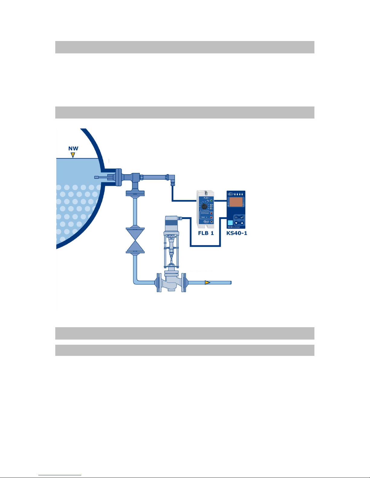
3. Schematic diagram
4. System description
4.1 Application
The TDS limiter FLB1 is used for continuous monitoring of the conductivity of liquids.
The conductivity is measured using a measuring cell. This consists of a special conductivity
electrode and tank wall or protective tube.
The requirements of EU Directive 2014/68/EU, standards EN 12952-11 and EN12953-9,
waterlevel 100 (Wasserstand 100) are taken into account.
Level probe EL22
TDS-valve ASV2
5

Probes for use with the FLB1:
4.2 Function
If a conducting liquid is in the measuring cell, the feeding triangular voltage drives a current
through the liquid. The value of this current is proportional to the conductivity of the liquid in the
measuring cell. This value is detected by the evaluation unit and converted into the 4-20 mA
interface. The current is simultaneously converted into a voltage. This voltage is amplified
depending on the position of the limit switch and compared with a reference. If the result of the
comparison is greater than or equal to the reference, the relay is de-energised and the contacts
open the burner chain. The warning light "Fault" (Störung) lights up. If the conductivity of the
liquid drops below 78% of the set limit, the relay is energised again. The warning light "Fault" is
extinguished.
This function can be checked by pressing and holding down the "Test K" key. If there are
malfunctions of the system, e.g. due to power failure or a short circuit, the evaluation unit reacts as
if the conductivity has exceeded the limit value.
The warning light "U B"
indicates that the operating voltage is present.
5. Design and installation FLB1
The device is supplied in a plastic plug-in housing for fitting into switch cabinets. The housing is
designed for quick fitting with a spring catch for the DIN EN 50022 standard 35 mm carrier rail and
for screw fixing on a mounting plate.
5.1 Installation dimensions and descriptions
Trimmer N for zero calibration
Trimmer T for temperature compensation
Trimmer Z for cell constant
1 = Conductivity limit setting
2 = Jack plug Ø 3.6 mm, for connection of a
measuring device for setting
Name PS TS Connection Feature
Type EL18 32 bar 239°C G ½“ Piping-with flange mounting
EL22 32 bar 239°C G ½“ frquently fitted with T-piece
EL23 80 bar 296°C G ½“ protective tube installation
1
2
Cable feedthroughs
Base with
connecting terminals
Front view
Side view
Base Hood
Screws for loosening the Snap fastening for
Hood from the lower part for carrier rail
6

5.2 Installation
Secure with protection class in accordance with current regulations
With top-hat DIN rail mounting for standard DIN46277 35 mm carrier rail
• Snap the device on the standard carrier rail.
• Loosen the fastening screws and remove the hood from the base.
• Connect to power supply (see Section 5.3).
Without top-hat DIN rail mounting
• Loosen the fastening screws and remove the hood from the base.
• Loosen screws and remove the DIN rail adapter.
• Drill the marked points in the base with a Ø4.3 mm drill.
• Fit base on base plate with 2 M4 screws.
• Connect to power supply (see Section 5.3).
5.3 Electrical connection
The device terminal strip is live during operation!!
Before working on the device disconnect it from the mains!!
The device must be protected mains-side by the operator with a max. 2A fuse!
If inductive consumers are connected, voltage peaks occur when switching
off. For this reason, connected inductive consumers (e.g. contactors) must be
provided additionally with an RC circuit: e.g. 0.1µF / 100Ω.
Caution electrica l voltage
Caution
Caution electrica l voltage
7
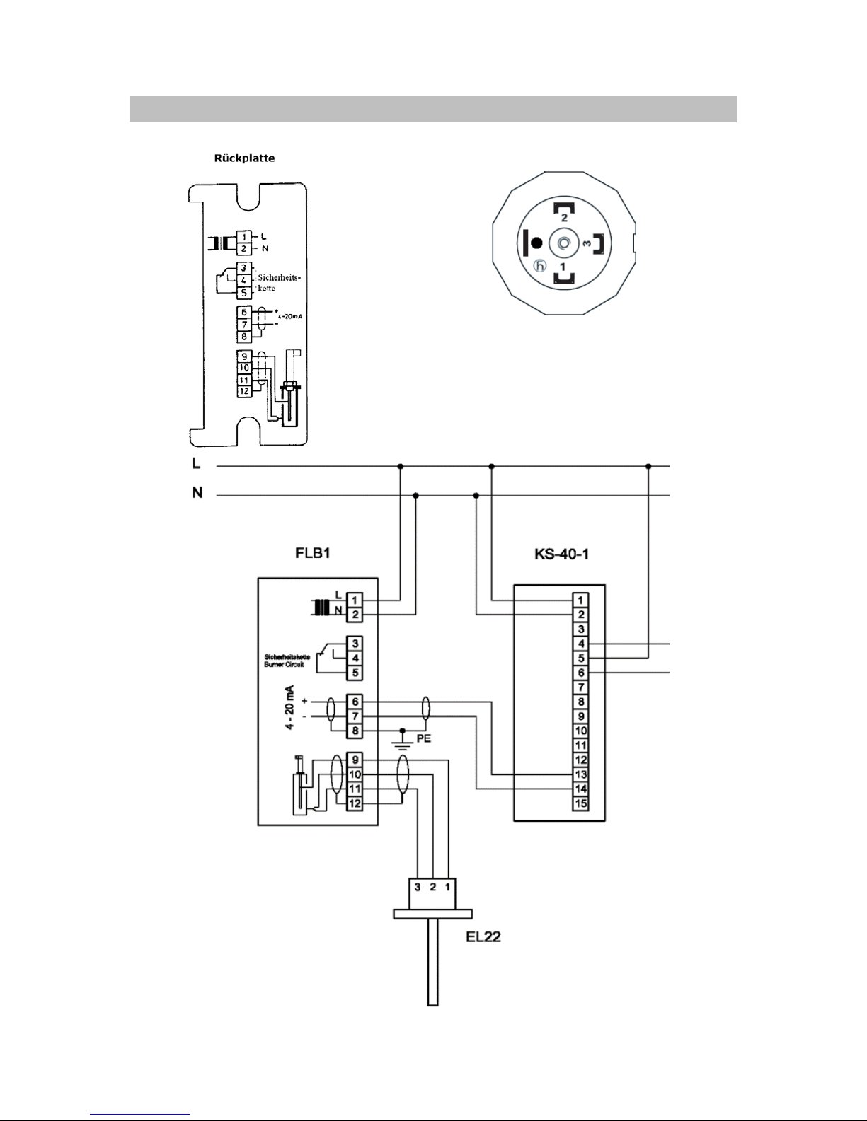
5.3.1 Wiring diagram
Probe plug
1 Electrode rod
2 GND
3 GND
● -
Back plate
Safety
chain
8

5.3.2 Procedure
Connect according to wiring diagram (5.3.1).
• Pierce or pull out cable feedthrough and feed connection cable through.
• Check supply voltage. See name plate for permissible voltage.
• Use a shielded connection cable for the probe: e.g. LIYCY min. 0.75 mm² up to a max.
length of 50 m. LIYCY min. 1.5 m² up to a max. length of 100 m (see note).
• Use a shielded cable for the current output (see note).
• Only connect shielding on the FLB1 control unit (terminal 12).
• After connecting to the power supply – with the device disconnected – place the hood on
the base and tighten the fastening screws.
• Fit electrode according to separate assembly instructions and connect as in the wiring
diagram.
When installing it, check whether the cables used are UV-resistant and that UV
protection is ensured on the installation side if necessary.
The cable must not come into contact with heat-conducting parts.
For aligning the probe plug to the local circumstances, the upper nut can be released (∅ 33.5mm).
In doing so, take care not to move the plug in the probe!! (SW24).
The contact carrier can be carefully turned into the correct position.
On refitting ensure that the seal is correctly seated! Retighten the upper nut without moving the
plug in the probe.
The connector plugs must be wired according to the wiring diagram.
Caution
9

6 Fitting the probe
It is essential to remove the cardboard protective tube for transport before
installation!
If several probes are screwed into one flange, the probe plug and the associated
probe should be labelled to prevent confusion!
Screwing in the probe
• Unscrew the probe plug
• Clean and check sealing surfaces
• Insert (new) sealing ring
• Grease the thread with heat-resistant solid lubricant (e.g. graphite).
• Screw in and tighten the probe, max. tightening torque Md = 140 Nm.
• Fit into the boiler before connecting the power.
Do not seal thread with PTFE tape or the like!
When commissioning the boiler, check the probe screw connection in the flange
for leaks and retighten if necessary!
Caution
Caution
Caution
10

6.1 EL22
This probe is fitted horizontally into the boiler as standard using a T-piece.
This enables the concentrated water, which is measured, to be directly discharged.
In order to determine the length, note that there should be a free space of 40mm around the
measuring tip.
11

6.2 EL23
This probe is fitted as standard using a protective tube.
12

6.3 EL18
This probe is fitted as standard using a flange in a pipe. With intermittent flow, a measurement can
then be carried out and TDS reduction can be started.
13

7. Adjustment
Do not carry out adjustment until all the system components are installed.
Switch on the mains voltage, the green warning light "U B"
lights up.
Measuring instruments required for calibration:
• Multimeter (preferably digital multimeter)
• Conductivity measuring device (preferably with temperature compensation)
7.1 Zero calibration
Requirement: The measuring tip of the conductivity electrode is not in contact with the water.
Depending on the installation of the electrode, lower the water level in the boiler or empty the
measuring line.
Connect the multimeter to the Ø3.6 mm jack socket (8) or to the terminals (6 and 7) and set a
current of 4 mA with the potentiometer "N".
• Turning the potentiometer clockwise gives larger values.
• If the value “4 mA” cannot be set – check the electrical lead for compliance with
the specifications in the wiring diagram.
7.2 Sampling
Requirement:
• Boiler in operating mode
• Measuring tip of the dedicated measuring electrode is surrounded by boiler water
Remove boiler water via the sampling cooler and determine the conductivity "K
actual
" in μS/cm
relative to 25°C using a conductivity meter.
Caution
14
7.3 Temperature calibration
Requirement:
• Boiler in operating mode
• Measuring tip of the dedicated measuring electrode is surrounded by boiler water
• Calculate the current to be set according to the equation
I = 4 + 16 x K
actual
[mA] / K
max
.
Example: K
actual
= 2000 μS / cm; see point 5.2 Sampling
K
max
= 10000 μS/cm; see scale value [K x 1000 μS/cm] on the front of the device.
I = 4 mA + (16 mA x 2000 / 10000) = 7.2 mA
Connect the multimeter to the Ø3.6 mm jack socket (8) or to the terminals 6 and 7 and set the
calculated current with the potentiometer "T".
• Turning the potentiometer clockwise results in smaller values.
• Up to 20 revolutions in one direction may be necessary.
If the calculated current cannot be set, the factory-set cell constant on the device is to be
corrected: set the calculated current via the potentiometer “Z”. Then carry out the calibration
again as described under points 5.1, 5.2 and 5.3.
If, in spite of following the above steps, calibration is not possible, the following error eliminations
are to be checked in addition:
• Press the "TEST K" key.
If the circuit is interrupted at the terminals of the connection block (3 and 4), a fault in the
FLB1 can be excluded.
• Check the correct fitting of the conductivity electrode according to the operating
instructions and the electrical connection according to the wiring diagram.
Do not remove the hood until the device has been disconnected from the
mains.
The capacity of the cable must not exceed 50 nF.
• To extend the contact life of the relays we recommend the use of commercial RC
combinations or an appropriate varistor when using inductive consumers (e.g. 0.1
µF/100 Ohm oder S07k275 varistor).
• See data sheet for further information.
Caution electrical voltage
Caution
15

8. Limit setting (maximum value)
Standards 12953-10 and 12952-12 contain requirements for the boiler water and the feedwater
according to the permissible operating pressure.
8.1 Setting the FLB1
Set the desired limit value for maximum conductivity with the limit switch “K” taking into account
the applicable directives.
9. Technical Data
9.1 Device data - Evaluator
Component identification mark: TÜV ID: 0000006175
CE identification number: 0035
Power supply: 230 V ± 10% / 50-60 Hz
Power consumption: approx. 4.5 VA
Device fuse: 80 mA/T
Protection type as per DIN EN 60529: IP 40*
All. ambient temperature: 0 – 60°C
* in accordance with the German regulation VdTÜV-Wasserstand 100, 4.90, IP 54 protection class must be
ensured in the boiler area.
9.2 Device data - Contacts
Burner shutdown: Protection voltage: max. 250 V AC
Switching current: max. 5 A resistive
Power interface: 4 – 20 mA
Electrical conductivity of the liquid: 0 μS / cm ≤ æ ≤ 10,000 μS / cm
0 μS / cm ≤ æ ≤ 1,000 μS / cm
Adjustable limit value "K" at 25°C: 1,000 μS / cm ≤ æ ≤ 10,000 μS / cm
100 μS / cm ≤ æ ≤ 1,000 μS / cm
16

Warranty
We accord a warranty period of 24 months on our products. A condition for that is
appropriate treatment according to these installation and operating instructions. The
warranty for wear and spare parts is restricted to material defects and construction faults.
Level probes are wear parts and are
not
subject to warranty.
IGEMA GmbH
Antwerpener Str. 1
D-48163 Münster
Germany
Tel.: +49 25 01 9 24 24 0
Fax.: +49 25 01 9 24 24 99
info@igema.com
www.igema.com
This high quality IGEMA product has been designed, manufactured and tested
using the
QM System specifications in accordance with DIN EN ISO 9001: 2000.
If the device supplied shows transport damage or gives cause for complaint in
spite of our final quality control please contact our SERVICE department by return.
Telephone
+49 (0)241- 5687-0.
17
 Loading...