


Triton House
Crosby Street
Stockport
SK2 6SH
England
TOCSIN i700
INSTALLATION
AND
USER INSTRUCTIONS
Tel: +44 (0)161 483 1415
Fax: +44 (0) 161 484 2345
Email: sales@internationalgasdetectors.com
Website: www.internationalgasdetectors.com
FS646773
EMS696504
REF: ROS 66-8 V10.1

Table of Contents
Specification
CE Declaration
Overview
Interface Wiring
19" Rack Systems
Addressable relay Cards
Wiring Relay Outputs
Powering 3rd Party Devices
Operating System
Accepting and Resetting Alarms
User Menu (Password 100)
Zero & Calibrate Command
Setting Alarm Levels
Copy Alarms
Common Alarms
Engineering Menu (Password 50)
Channel Setup
FIND Command
Test Addressable Sensors
Testing Addressable Relays
Test FIRE Input Channels
Production Menu (Password 200)
Alarm Actions
Mimic Panels
Highway Splitting
Integrated Battery Backup
Battery Backup Run Time
Modbus
3
4
5
6
16
17
18
19
20
21
24
26
27
28
30
31
34
36
39
40
41
42
43
44
45
46
49
51
Page 2 of 52

This product must be earthed in accordance with local safety regulations.
The Control Panel leaves the factory configured for the supply voltage stated on the customers order.
Standard voltage and frequency range is:-
AC Mains Powered 230V AC (176 to 264V AC) 47 to 63 Hz
Switch Selection Option 110V AC (88 to 132V AC) 47 to 63Hz
DC Low Voltage Powered 18 to 30V DC
NOTE: Operation on an incorrectly selected supply voltage will damage the controller
Should the control panel be used in conjunction with portable generating equipment, care should be taken to ensure that
the electrical supply is within the tolerance band described above. The control panel may be stored at temperatures
between 0 C and 55 C. If stored at low temperatures and then brought into a warmer environment, condensation may
form on some components. In such a situation , this condensation should be allowed to evaporate prior to use of the
equipment. If stored at high temperature, care should be taken to ensure that humidity condensation does not enter
critical electrical components, for example the power supply. The Control Panel is designed to operate within
specification for ambient temperature between 0 C and 55 C, relative humidity up to 95% ( non-condensing ).
On installation alarms will need to be configured to signal when monitored gas levels have breached safe limits. The
control panel will be shipped in a semi-configured state which must be checked and configured during commissioning to
match the applications cause and effect requirements. Failure to do so will result in an ineffective system.
Who should read this manual.
0 0
o o
!Warning !
This manual is intended for use by trained installers of gas detection systems who are technically competent and
have all necessary tools to undertake installation and maintenance on this type of equipment.
Failure to install and maintain the equipment properly can render the detection system ineffective.
You should not undertake any of the procedures in this manual if you do not have access to the correct equipment,
have not undertaken training on this or similar equipment or are not technically qualified to install this equipment.
Calibration gases and test equipment is available from IGD.
Power Source 88 to 132V AC (110V AC Selected) or 176 to 264V AC (230V AC Selected)
47 to 63 Hz 150 Watts DC Option Available
Display 2 x 16 backlight LCD
Operating Temperature 0°c to 55°c
Operating Humidity Up to 95% non-condensing
Resolution 0.00% or ppm Range Dependant
Update Rate 1 Second
Size (mm) 255 (H) x 265 (W) x 100 (D)
Protection Standard IP54
Inputs Up to 4 or up to 8 x 4-20mA loops
8 analogue 4-20mA loopsInputs
2 x RS485 data highways for up to 64 detectors (700+)
Outputs (Standard)
3 x configurable SPCO relays (7 Amp non conductive load)
1 x fault SPCO relays (7 Amp non conductive load)
1 x solid state audio/sounder 24VDC
1 x solid state visual/flasher 24VDC
Outputs (Optional)
Additional 8 way relay cards, I/O Nodes
Gas Detectors
Check ratings for maximum I/O from PSU
Optional Equipment Battery backup 1.2Ah or 2.4Ah
CE Declaration BS EN61000-6-4 EMC Compatibility 'Emissions'
BS EN 61000-6-2:2001 EMC Compatibility 'Immunity'
BS EN 61010-1: 2001 Safety requirements, electrical equipment
Weight 3.65 KG
Page 3 of 52

Issuers name and address:
EC Declaration of Conformity
Oliver IGD Limited of
Triton House
Crosby St,
Stockport, SK2 6SH
Declares that the product listed as:
TOCSIN i700
Addressable & analogue Gas Detection Control Panel
United Kingdom
Are in conformity with the provisions of the following European Directive(s) when installed, operated, serviced and maintained
in accordance with the installation and operating instructions contained in the product documentation.
2004/108/EC EMC Directive
2006/95/EC Low Voltage Equipment Directive (note not applicable to 24V DC Powered Versions)
And that the standards and/or technical specifications referenced below have been applied or considered.
EN 61779-1:2000
Electrical apparatus for the detection and measurement of flammable gases, general
requirements and test methods.
EN 50271:2001
Electrical apparatus for the detection and measurement of combustible gases, toxic gases or
Oxygen: requirements and tests for apparatus using software and or digital technologies.
Excluding requirements for SIL
EN 61000-6-2: 2005
EN 61000-6-4: 2007
EN 61000-3-2/A2: 2009
EN 61000-3-3: 2008
EMC Generic standards. Immunity for industrial environments
EMC Generic standards. Emission standard for industrial environments
EMC Limits. Limits for harmonic current emissions (equipment input current ≤ 16 A per phase)
EMC Limits. Limitation of voltage changes, voltage fluctuations and flicker in public low-voltage
supply systems, for equipment with rated current ≤ 16 A per phase
Technical File Reference
T700-TF9
Oliver IGD Limited Operate an
Independently assessed ATEX/IECEX
QAN.
EMC Tested by:
TUV - SUD
Quality Assurance Certificate Number
16PQAN0014
Quality Assurance Notification Number:
2585
Units 16-18 Abenbury Way,
Wrexham Industrial Estate,
Wrexham, LL13 9UZ
United Kingdom
Oliver IGD Limited operate an independently
assessed ISO9001:2015 Quality Management and
ISO14001:2015 Environmental Management System
Certificate Numbers
FS0646773 & EMS696504
BSI Assurance UK LTD,
London, W4 4AL
United Kingdom
Octagon House
Concorde Way
PO 15 5RL Fareham
Certificate Number
E8N 15 02 91327 001
TUV Certificates and reports can be checked on-line at
https://www.tuev-sued.de/industry_and_consumer_products/certificates
Select Oliver IGD when prompted on the website to view certificates
Issued by: Oliver IGD Limited, Stockport, SK2 6SH , United Kingdom
Signature: Declaration of Conformity in accordance with EN ISO/IEC 17050-1:2004
Name: Andrew J Collier M.I.O.D
Position: Managing Director Date: 1.January 2019 Declaration Ref: I700-DEC-1
Page 4 of 52
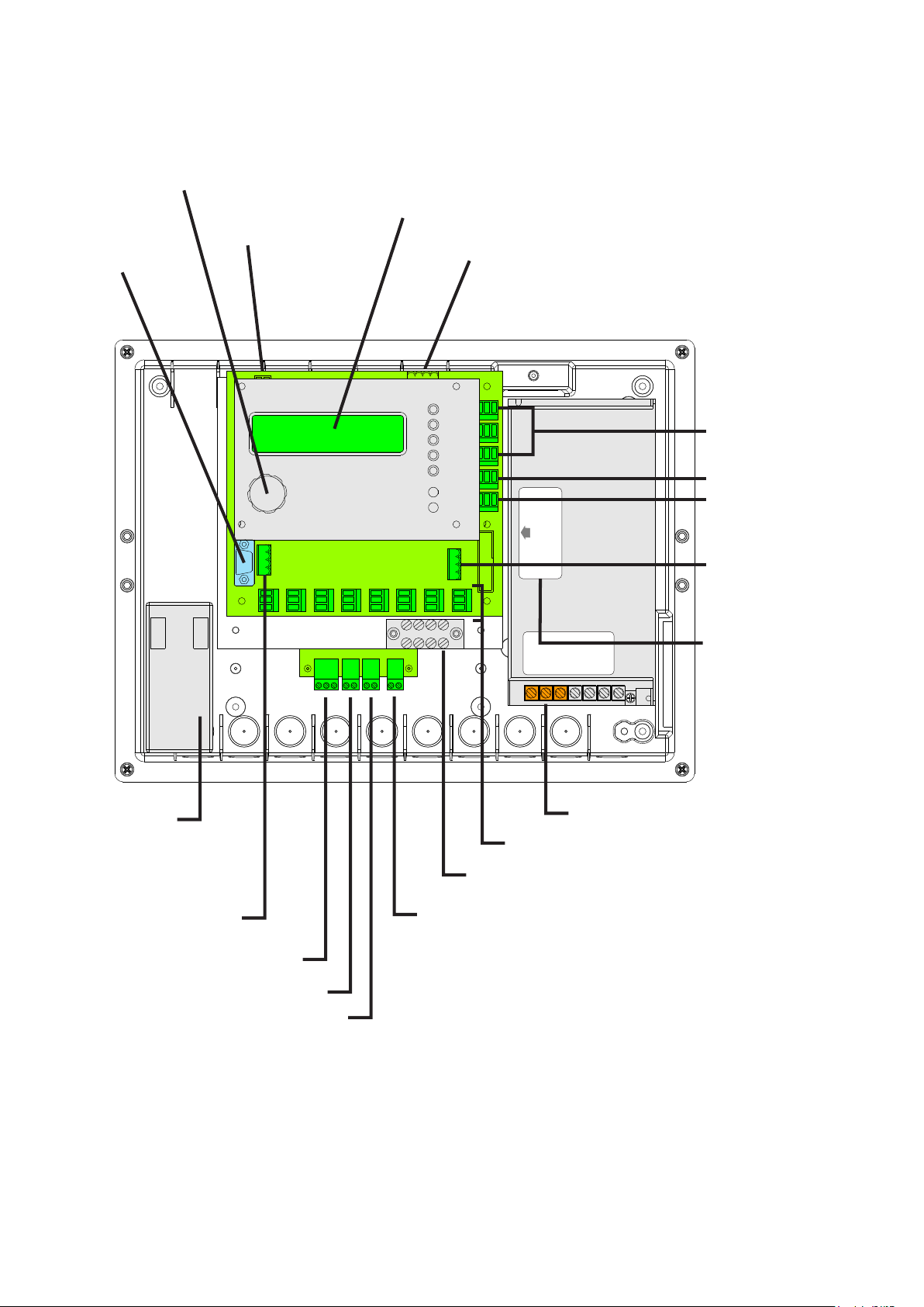
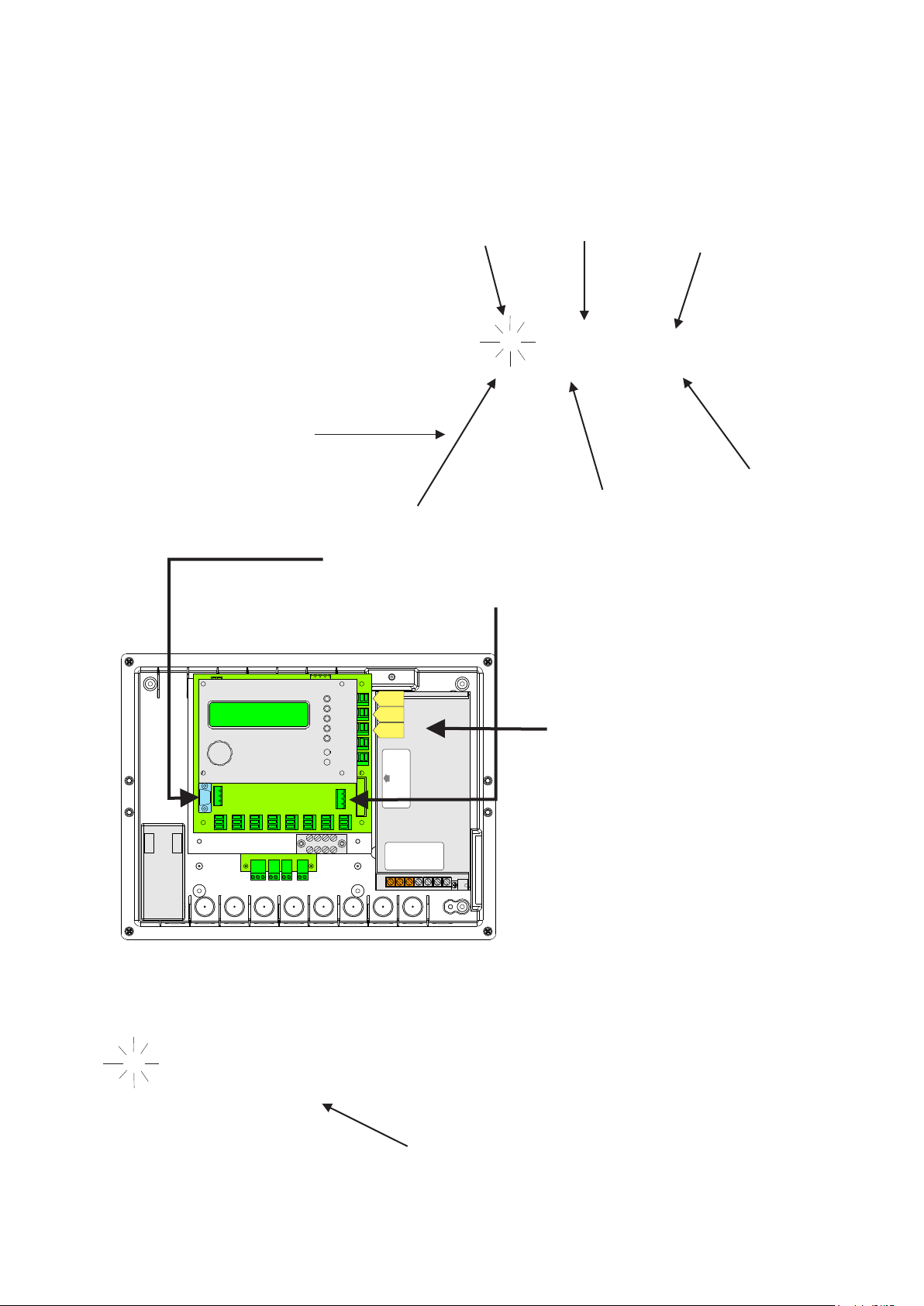
Tocsin 700 Panel Overview
Jog Wheel
24V DC Panel Power
RS232 Comm
Port
2 x 16 LCD Display
Digital Inputs
3 off Configurable
Relay Outputs
With Activation
Indication Lamps
Backup Battery
RS 485 Detector
Data Highway
Connector Port 2 ‘C2’
(Addressable Versions)
Battery Connector
PSU SET TO 230V AC
Fault Relay Outputs
Sounder/Flasher
Outputs
RS 485 Detector
Data Highway
Connector Port 1
‘C1’
(Addressable Versions)
L N E
Label Indicates
Voltage Input as
Shipped From Factory
By Default 230V AC
Use Switch to Change
if Necessary
Mains/DC Input
(Check Supply Option Before Use)
8 off 4-20mA Loop Inputs
Grounding Points
Volt Free Contact Opens On Loss of Mains Power
Power to Main PCB
24V PSU Input
IMPORTANT
Control panels are usually shipped pre-configured with a basic alarm strategy. Before installation check the
documentation provided to ensure the programmed cause and effect matches the site requirement. If it does
not then the system will need to be re-programmed by the installer using the embedded panel software or
PC based T700 setup software.
When first powering systems which include an IGD battery backup the batteries MUST be connected first for
correct operation. During initial startup the panel software will check the battery condition, if mains power is
applied first then the batteries cannot be functionally checked and the panel will report an error.
Page 5 of 52

In all Cases:
Tocsin 700 Interface wiring
VISUAL
OUTPUT
OUTPUT
+24V DC
B
A
0V
0V DC
4-20mA IN
+24V DC
GND
COM
NO NC
GND
AL1
AL2
AL3
24V DCAUDIO
Relay contact ratings.
7A @ 250V AC Non-Inductive
7A @ 30V DC Non-Inductive
Spike suppression must be fitted
Note that FAULT relays are normally
energised on power up.
These 3 relays can be assigned,
named, zoned etc using the Tocsin
700 operating software.
Dedicated fault relay output, this output
is energised in normal operation
SOUNDER O/P
Sounder Alarm
24V DC
Max Current
150mA 24V DC
WARNING LAMP O/P
Note Flasher on
with alarm level 1.
Buzzer on with
alarm level 2.
1.5mmSQ See Panel
for recommended cable
types. Typical max cable
run 1000M.
1.5mmSQ See Panel
for recommended cable
types. Typical max cable
run 1000M.
Addressable control panel versions only.
See 'Addressable Sensors' Section
TOCSIN 102/A
Enclosure
Ground
Blue
Red
TOXIC GAS
DETECTORS
TOCSIN 102IR
Enclosure
Ground
Black
Red
Blue
FLAMMABLE GAS/
CO2 DETECTORS
Page 6 of 52

Tocsin 700 Interface wiring...continued
0V DC
4-20mA IN
+24V DC
GND
1.5mmSQ See Panel
for recommended cable
types.Max cable
run 1000M.
Common
Active
Compensator
P Y W
CHASS
ZERO
CAL
24V DC
B
A
GND
mA
360
mA+360CONC0V mA-
FAULT
T106P Pellistor
Flammable Gas
Detectors
Page 7 of 52

Tocsin 700 Interface wiring...Digital Port
Located at the top edge of the Tocsin
700 card is a 4 way connector used to
allow digital interface to the Tocsin 700
operating system as follows:
1 2 3 4
0V common
Reset Alarms
Password Inhibit
Inhibit Alarms
Page 8 of 52

Tocsin 700 Interface wiring...continued
Tocsin 700 to Tocsin 103 2 wire Detector Series
0V DC
4-20mA IN
+24V DC
GND
4-20mA Toxic
And Oxygen Gas
Detectors
Enclosure
Ground
24V DC
SCREEN
4-20mA
1.5mmSQ See Panel
for recommended cable
types. Typical max cable
run 500M.
Page 9 of 52

Tocsin 700 Interface wiring...continued
Tocsin 700 to Tocsin 103 3 wire Detector Series
Cable Guidance Panel
It is imperative to use cabling which suits
the environment in which the T700 and its
sensors are to be used. The following is intended
as a guide.
Fit 1.5mm SQ cable for analogue systems
Fit 2.5mm SQ cable for addressable systems
Use
Pirelli LSX type cable for office/light commercial
un-zoned installations
Steel Wire Armored or CY cable for medium/heavy
industrial un-zoned installations
0V DC
4-20mA IN
+24V DC
GND
GND
Mineral Insulated Pyro cable for all hazardous
area zoned installations.
Note in all cases the T700 Panel must be installed outside
of any hazardous area and must be supplied via
a fused spur.
Enclosure
Ground
Screen
0V DC
24V DC
4-20mA
1.5mmSQ See Panel
for recommended cable
types. Max cable
run 1000M.
4-20mA Flammable
And CO2 Gas
Detectors
Page 10 of 52
Tocsin 700 Interface wiring...continued
0V DC
4-20mA IN
+24V DC
DIP Switches For Relay O/P
And Sounder O/P Enable
GND
T103 FREON Gas
Detectors
Enclosure
Ground
NO
COM
NC
0V DC
24V DC
4-20 OUT
1.5mmSQ See Panel
for recommended cable
types. Typical max cable
run 500M.
Sensitivity Adjustment
Factory Preset
Do Not Adjust
Page 11 of 52

Tocsin 700 Interface wiring...continued
4-20mA IN
+24V DC
GND
FIRE AND SMOKE INPUTS (FACTORY OPTION)
NOTE THESE DETECTORS ARE RESET BY
INTERRUPTION OF THE POWER SUPPLY. THE
TOCSIN 700 WILL DO THIS IF THE CHANNEL IS
SELECTED AS A ‘FIRE’ AS A GAS TYPE, RELAY
OUTPUTS MUST BE SET AS LATCHING. NOTE
THAT THE POWER IS SUPPLIED TO THE INPUT
CONNECTORS IN BANKS OF FOUR. IF MIXING
WITH GAS DETECTORS SEGREGATE THE FIRST
FOUR INPUTS AS GAS DETECTORS AND THE
SECOND FOUR INPUTS AS SMOKE DETECTORS.
THIS IS A FACTORY FIT OPTION AND MUST BE
REQUESTED WHEN ORDERING THE CONTROL
PANEL. CHANNEL HARDWARE CONFIGURATION
IS DIFFERENT TO STANDARD 4-20mA INPUTS
INTERFACING TO FIRE AND SMOKE DETECTOR
DIODE BASES.
NOTE IF SUPPLIED IN THIS FORMAT THE INPUT
CONNECTORS INCORPORATE PROTECTION
DIODE. DO NOT USE WITHOUT THIS
CONNECTOR/DIODE
ASSEMBLY
NOTE LAST DEVICE IN LINE TO BE FITTED WITH
5K6 RESISTOR AS INDICATED
3
4SD DIODE BASE
1
6
5
4SD DIODE BASE
1
3
3
4SD DIODE BASE
5
6
1
6
NOTE: TYPE INDICATED IS TYPICAL OF NITTAN ST-I
CONVENTIONAL OPTICAL SMOKE OR HEAT DETECTORS. OTHER
MANUFACTURER CONNECTIONS MAY VARY.
5
Page 12 of 52
Tocsin 700 Interface wiring...continued, Addressable Systems.
+24V DC
B
A
GND
GND
2.5mm SQ Cable See Previous Note
120 Ohm Termination
Resistor on the Last
Detector in Line
Local Comms
Connector For
Palm Connection
B
24V
SCREEN
A
0V
24V
Red
Rx
White
Yellow
Tx
4-20
Blue
B
24V
SCREEN
0V
Black
B
24V
A
0V
24V
Red
Rx
Tx
White
Yellow
Blue
A
0V
SCREEN
Local Comms
Connector For
Palm Connection
24V
SCREEN
4-20
0V
Black
B
A
0V
Tocsin 102 Addressable
Series Detector Head
Use Junction Boxes Suitable for Area Classification
Tocsin 102 Addressable
Series Detector Head
Page 13 of 52

Tocsin 700 Interface wiring...continued, Addressable Systems Cont.....
+24V DC
B
A
GND
GND
2.5mm SQ Cable See Previous Note
360
mA
GND
A
B
24V DC
CHASS
Compensator
ZERO
CAL
FAULT
P Y W
Common
Active
mA+360CONC0V mA- mA+360CONC0V mA-
360
mA
GND
A
B
24V DC
CHASS
Compensator
ZERO
CAL
FAULT
P Y W
Common
Active
mA+360CONC0V mA-
360
mA
GND
A
B
24V DC
CHASS
Compensator
ZERO
CAL
FAULT
P Y W
Common
Active
Use Junction Boxes Suitable for Area Classification
Page 14 of 52

Tocsin 700 Interface wiring...continued, Addressable Systems Cont.....
+24V DC
B
A
GND
GND
2.5mm SQ Cable See Previous Note
Addressable Relay Outputs
These come equipped with two volt
free contacts which can be set as
normally open or normally closed action
Use for beacon/sounders etc
Mix on the same loop as addressable detectors
MUTE ALARM MUTE ALARM
CHASS
24V DC
Set Address
B
A
4301
GND
mA
PWR M EN Al COMM
PALM
CHASS
24V DC
Set Address
B
A
4300
GND
mA
PWR M EN Al COMM
PALM
Use Junction Boxes Suitable for Area Classification
Page 15 of 52
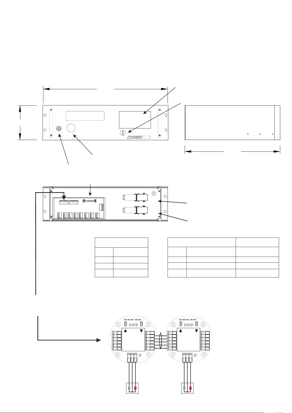
19" Rack Mount systems
Tocsin 700R 19" rack versions of the control panel are 24V DC powered and only interface as addressable
systems. The systems are shipped with an addressable relay card mounted to the rear which can be remote
mounted if required. Note that detectors are connected via the relay card connector shown below.
133.4
483.0
ADVA NCE D GA S DE TEC TI ON S YST EM
Jog Wheel
Alarm Sounder
External Addressable Relay Card
4208
4209
4210
4211
4212
4213
4214
4215
4216
70 0
RS485 to HUB
RS485 to HOST
or HMI PANEL
Optional Event Panel Printer
Optional Keyswitch
240.0
Connection to Addressable Gas
Detectors and Addressable Relays
Power and Modbus Connection
Detector Connector:
Pin 1 24V DC
Pin 2 Comm B
Pin 3 Comm A
Pin 4 0V DC
Power Connector: Cable
Pin 1 Comm B Grey
Pin 2 Comm A Green/Yellow
Pin 3 24 V DC Brown
Pin 4 0V DC Black
Addressable Gas Detectors and Addressable interface modules connect here
in the same manner described previously.
mA+360CONC0V mA-
ZERO
CAL
360
mA
GND
A
B
4101 41024102
FAULT
24V DC
CHASS
P Y W
Common
Active
Compensator
mA+360CONC0V mA-
360
mA
GND
A
B
24V DC
CHASS
Compensator
ZERO
CAL
FAULT
P Y W
Common
Active
Tocsin 106 Pellistor Flamable
Gas Detectors Shown
Page 16 of 52
Addressable Relay Card
Power out for
use in
conjunction
with relays
0V DC
24V DC
Relay status LED,
ON when Energised
In all Cases:
Relay contact ratings.
7A @ 250V AC Non-Inductive
7A @ 30V DC Non-Inductive
Spike suppression must be fitted
Note that FAULT relays are normally
energised on power up.
24V DC
A2
A1
Base Address set up
LED's and interface
for the relay card
Highways Connection
Pin 1 0V DC
Pin 2 Comm A
Pin 3 Comm B
Pin 4 24 V DC
Pin 1 0V DC
Pin 2 Comm A
Pin 3 Comm B
Pin 4 24 V DC
Highways Connection
Example fit
protection
diodes when
0V DC
switching
external DC
loads.
~
A1
~
A2
Example fit protection
supressors when
switching external AC
loads typical device
Farnell Ref 1438460
Normally Closed
Common
Normally Open
Relay Terminals
First Relay on
The Card (relays
number from
this one).
Page 17 of 52

TOCSIN i700 Relay Outputs
There are four relays directly fitted to the Tocsin i700 controller. These can be configured by the user to
activate on different alarm levels. One of the relays, is a dedicated system fault relay. See later programming
details regarding alarm and fault relays.
Switching DC Loads
Normally Closed
Common
Normally Open
Example fit protection
diodes when switching
external DC loads.
Switching AC Loads
Normally Closed
Common
Normally Open
Example fit protection supressors
when switching external AC loads
typical device IGD Part Number
5438601
24V DC
~
A1
A1
A2
0V DC
~
A2
In all Cases:
Relay contact ratings.
7A @ 250V AC Non-Inductive
7A @ 30V DC Non-Inductive
Spike suppression must be fitted
Note that FAULT relays are normally
energised on power up.
In all cases switched loads should have appropriate EMC protection as indicated in the diagram above.
Loads should be fused. DC inductive loads should not be powered from the controller PSU. Inductive
loads such as solenoids or motors can have high in-rush currents well above the steady state current
indicated on data sheets. These high in-rush currents can interfere with the correct operation of the
controller and so powering from the control panel is to be avoided.
Page 18 of 52

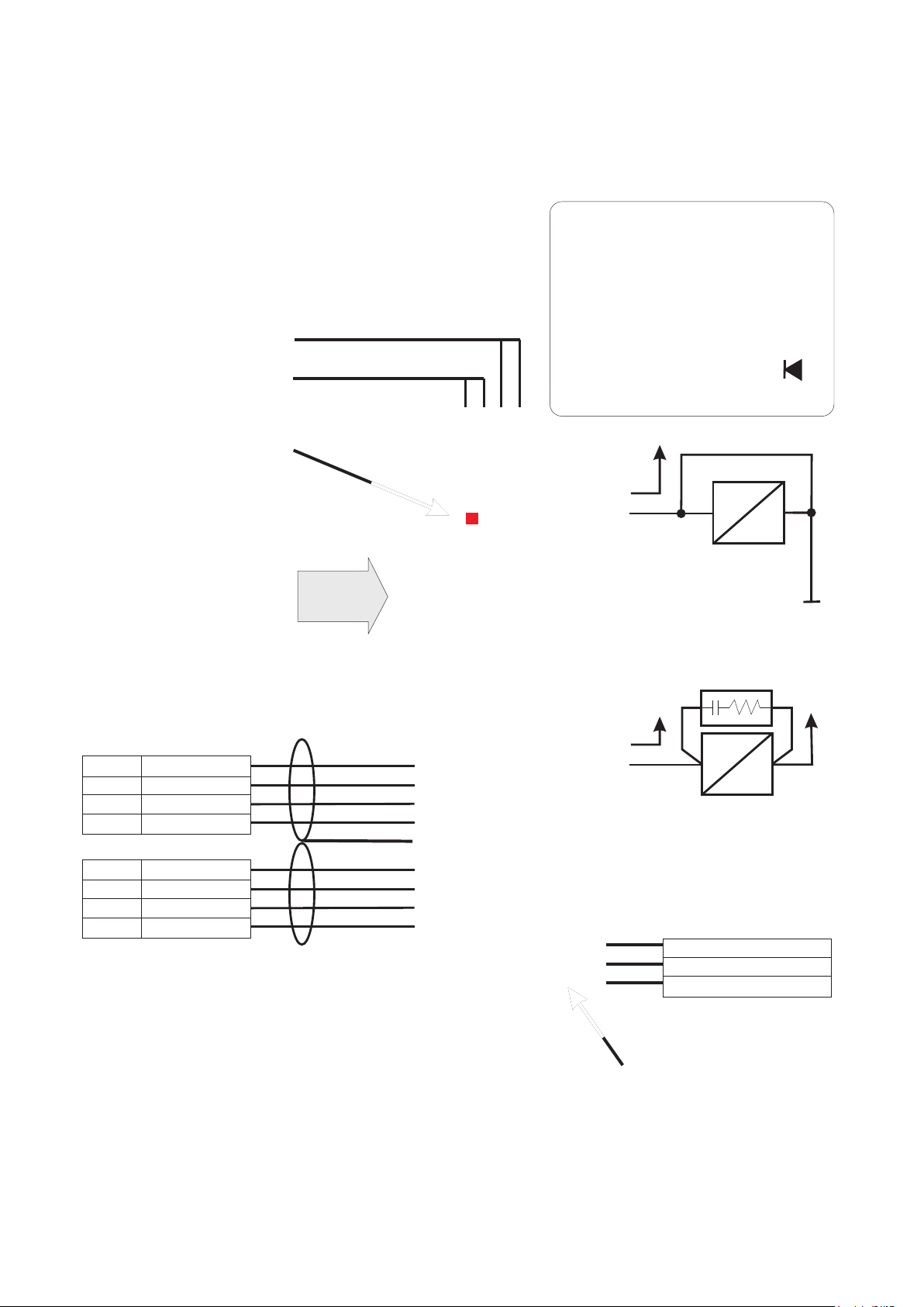
Powering Third Party Devices
In general third party devices should only be switched and NOT powered from the
Tocsin 700, (with the exception of beacons and sounders).
The Tocsin 700 controller has been extensively third party tested to ensure electrical
safety and EMC compliance in a number of installation formats.
Connecting third party devices which may place unknown power demands on the Tocsin
700 can result in damage and/or unintended operation and so is NOT recommended.
The requirement to power gas shut off solenoid valves is common and so has been
tested. The following tables and wiring arrangement will allow a suitable solenoid to
operate correctly from the control panel.
Note this connection is
direct from the 700
PSU. Incorrect
connection can
damage the 700 and
power supply. Check
polarity before
powering
Example fit
protection
diodes when
switching
external DC
loads.
Tocsin 700 Model Max Solenoid
Load @ 24VDC
60W PSU Version with
8 Detectors 1.5A
150W Version with
50 Detectors 1.5A
0V
24V
A2
A1
Do note exceed the ratings listed on this data sheet. Also note that some solenoid
valves can have significant in-rush current which may adversely affect operation and
overload the power supply.
Page 19 of 52

Operating System
Operating System Overview
2 Line x 16 Character LCD Display
Output Relay 1 Lamp
Output Relay 2 Lamp
Output Relay 3 Lamp
System Fault Lamp
Power On
Jog Wheel
Rotate the jog wheel to move
up and down the system
menus.
Press the jog wheel to make
a selection or to accept/silence
an alarm
The Tocsin 700 series gas detector control panels are designed to be as flexible in operation as
possible. The system software allows the owner/installer to configure the following functions:-
Configure input type, not only the selection of pre-programmed input gases but also the option
to define an input type and scale the incoming 4-20mA signal to match. For example,
pressure, temperature, distance etc
Decide alarm levels for each input and decide, rising,falling or latching alarms and which relay
to asign to which inputs to allow, zoning etc
Logical naming of inputs, for example 'boiler 1' (max 8 characters)
Set the display scan rate
Zero and calibrate each channel from the control panel.
In addition the Tocsin 700 control panel can be 'hooked up' to a PC or PALM device via its serial
programming link to allow system configuration using Oliver IGD software. This allows not only preconfiguration of the panel prior to commissioning but also a record of how the system was set up.
+Always refer to the shipping manifest and test schedule for confirmation of the shipped
configuration.
Page 20 of 52

Accepting and Reseting Alarms
For most of its operating life the Tocsin 700 control panel and associated sensors will monitor for
whichever hazard it is configured for. The only requirement from the plant operator is to have the
system regularly calibrated, typically every 3 or 6 months depending on the nature of the gas
hazard. This section describes what happens at the control panel should the system detect a hazard
and go into alarm and how to accept the alarm and reset the control panel.
Step 1. The panel detects a gas hazard
Panel indicates which channel is in alarm
Panel indicates which alarm level has tripped
Panel indicates how many alarms in total have tripped
CH1 AL 1 TOTAL 2
CH1 AL 1 TOTAL 2
BOILER 1 AREA 3
BOILER 1 AREA 3
Relay outputs will activate dependant on the
system configuration
Alarm outputs (beacons and sounders) are active
if fitted.
The user programmed description for the sensor is displayed
Step 2. Operator Accepts The Alarms
Pressing the jog wheel will accept the indicated alarm. If there is more than one alarm tripped then
the next alarm is indicated on the display. Note that the total number of active alarms is indicated in
the top right of the display.
Once all alarms have been accepted the sounder output from the panel is de-activated, if a sounder
has been fitted it will silence. The relay outputs associated with the active alarms will still be
energised until the gas hazard has been cleared and the panel reset.
Once all active alarms have been accepted the display will read as follows:
WARNING
CH1 AL 1 TOTAL 2 OF 4
CH1 AL 1
It is important to have a site health and safety
PRESS RESET ALL
response in place in the event of alarm activation.
Gas detection systems are an indication that a
problem may exist but should not be relied on as a
f a i l s a f e s y s t e m . .
Pressing the jog wheel at this stage will reset the system. This de-activates any energised alarm relays
depending on the panel user alarm programming and the 'beacon' output. If the gas hazard is still present
then it will not be possible to reset the alarm.
Page 21 of 52

Tocsin 700 Menu System
1. Start up
12:23:01
OLIVER IGD LTD
2. Warming Up
Time 12:23:01
WARMING UP 01:49
Time in 24 hour format.
Company name is programmable in
EPROM Memory.
Warmup is displayed for the set period
3. Normal Display Mode
Normal display mode.
1 FLAM 0 % LEL
BOILER 1
In normal display mode the display will
auto scroll through all installed channels
at a user settable time. The time is
settable from 1 to 240 minutes.
Time is user programmable in seconds
and is programmed in the engineering
mode.
Normal display shows current channel in top left corner. Current channels measurement gas, reading
and measurement units.
The gas types are pre-programmed in the Tocsin 700 operating system. 23 Gas Types are preprogrammed and a further 4 gas types can be added by the user.
There are three pre-configured measurement types.
%LEL PPM %VOL.
Again the user can add a further two measurement types.
Page 22 of 52

4. Pre-configured Measurement Types
Display with %LEL (Lower Explosive Limit) Display
1 FLAM 0 % LEL
BOILER ROOM 1
Display with %VOL (% by Volume) Display
1 O2 0 % VOL
N2 STORE 1
Display with ppm (Parts Per Million) Display
1 CO 12 PPM
CAR PARK LEVEL 1
The second line displays the channels
description, up to eight characters long this is
editable using the Tocsin 700 menu system.
5. Menu System
The menu system is accessed by firstly selecting a channel. This is done by rotating the Jog Wheel.
Clockwise increases the channel indicated. Anti clockwise decreases the channel indicated. When the
switch is rotated the back light illuminates and the unit stops it's auto scrolling function. If no channel is
selected or if the button is not rotated within a minute then the unit returns to it's normal auto scrolling
mode. In auto scrolling mode each channel fitted to the control panel is sequentially displayed for a
fixed time period.
To select a channel to work on the Jog Wheel is pressed. This takes the user into the main menu.
The channel selected is shown on the top line. This information updates with the users commands.
The gas concentration also updates in this mode, this aids the user in calibration.
Channel Number
Gas Type
Current Reading
Units
1 O2 0 % VOL
`
Note these
ZERO
configuration
menu’s are
password protected
Current Command Option
Pressing the jog wheel will
activate this command.
Page 23 of 52

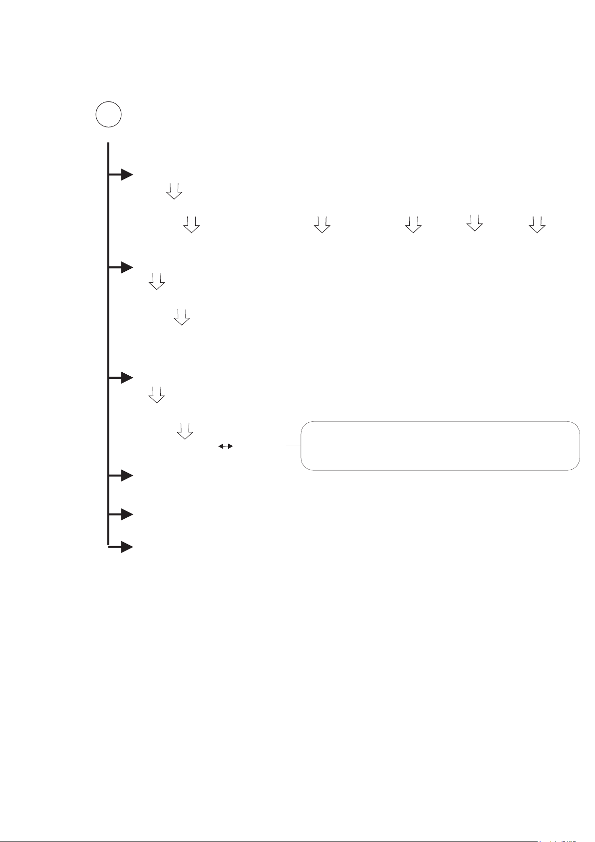
7. Menu System Overview Setup Menu’s (User Menu)
Press and hold down the jog wheel. The system will
1 O2 0 % VOL
ZERO
request a password. Once entered correctly the following
menu sequence will be displayed.
Rotate to move down a menu. Pressing the button selects the sub menu one column
to the right
ZERO
ABORT CONTINUE
CALIBRATE
ABORT CONTINUE
ALARM 1 SETUP
PASSWORD CODE
100
SELECT SENSOR SET ALARM TYPE SET LEVEL CABLE ACTION SET RELAY OP
1 to 64 Rising
Falling
Rising Latch
Falling Latch
rotate
jog wheel
to set
Select
I/O
Cable 1
or 2
Set ‘N’
For Normal
Operation
or
1 to 37
or
address
Set ‘M’
ALARM 2 SETUP
For To Allow
Muting Action
SELECT SENSOR SET ALARM TYPE SET LEVEL CABLE ACTION SET RELAY OP
1 to 64 Rising
Falling
Rising Latch
Falling Latch
rotate
jog wheel
to set
Select
I/O
Cable 1
or 2
Set ‘N’
For Normal
Operation
or
1 to 37
or
address
Set ‘M’
ALARM 3 SETUP
For To Allow
Muting Action
SELECT SENSOR SET ALARM TYPE SET LEVEL CABLE ACTION SET RELAY OP
1 to 64 Rising
Falling
Rising Latch
Falling Latch
rotate
jog wheel
to set
Select
I/O
Cable 1
or 2
Set ‘N’
For Normal
Operation
or
1 to 37
or
address
Set ‘M’
COPY ALARM SETUP
For To Allow
Muting Action
2
COPY FROM CH (select from 1 to 64)
TO RANGE CH (select from 1 to 64) - (select from 1 to 64)
Page 24 of 52
7. Menu System Overview Setup Menu’s Continued
2
COMMON ALARMS
SELECT GROUP FROM CHANNEL TO CHANNEL ALARM SET RELAY OP
PASSWORD CODE
100
1 to 16
DESCRIPTION
SELECT CHANNEL (1 to 64)
use jog wheel to enter up to 8 character description
DISABLE CHANNEL
SELECT CHANNEL (1 to 64)
ENABLE DISABLE
CHANGE CHANNEL
ENGINEER MENU
Select the from to range
for the channel alarms
to be grouped
Note the display option shows what you are about
to change the option to. Therefore if the channel is
already ENABLED then the option shows DISABLE
AL1,
AL2
or AL3
1 to 37
or
address
EXIT
Page 25 of 52

The bottom line of the display shows the command available for selection and is altered by
rotating the jog wheel.
5.1 The Zero Command
With the panel in normal display mode,
rotate the jog wheel to the desired
1 O2 0 % VOL
ZERO
channel and press the jog wheel. Now
rotate the jog wheel until the bottom line
of the display reads zero. At this stage
apply zero gas to the gas head and allow
the reading to stabilise.
1 O2 0 % VOL
Once the reading has stabilised
press the jog wheel and the bottom
line will change to read zeroing. The
Tocsin 700 now averages the
incoming signal for a few seconds
before applying any necessary zero
correction. Once complete the
bottom line of the display changes to
read ‘PASSED’ or ‘FAILED’ . If the
zero operation passed the zero
correction is applied.
5.2 The Calibrate Command
1 O2 0 % VOL
CALIBRATE
1 O2 0 % VOL
SET CAL BOTTLE
ZEROING
This function allows the user to calibrate a channel.
As in the case of the zero function, select a channel to
be calibrated and rotate the jog wheel until the
'Calibrate' option appears on the bottom line of the
display.
The display set bottle will appear
for a few seconds to prompt the
input of the calibration gas set
point.
1 O2 0 % VOL
The bottom line of the display now changes to
100
allow the input of the calibration gas value. The
display will indicate the last value used to
calibrate the channel. Rotate the jog wheel:
Clockwise to increase the value.
Anticlockwise to decrease the value.
With the calibration gas applied to the gas head allow the reading
to stabilise then press the jog wheel. The display will change to
'calibrating' for a few seconds as the reading is averaged and new
calibration constants calculated. PASSED or FAILED will be
displayed and once complete the display will return to step A.
1 O2 0 % VOL
CALIBRATING
Page 26 of 52
5.3 Set Alarm Level Setup for Alarm Levels 1,2 and 3
Select the ALARM 1 SETUP from the user
menu. And the following display will be
shown. Note you are now editing alarm
level 1 settings. By changing the channel
number you can check and set all alarm
detector
channel
number
level 1 settings for each channel
connected. Press and hold the jog wheel to
exit the screen then select ALARM 2 and
ALARM 3 SETUP’s.
Gas
Relay Action as:
Rising
Falling
Rising Latching
Falling Latching
Set Alarm Level
As you enter this menu screen
the channel number will be
flashing.
Press the jog wheel to move
sequentially around the screen.
With the item you want to change
flashing rotate the jog wheel to
alter levels or options.
01 RIS&L L = 19
C1 N RELAY = 1
Cable Number (1 or 2) For
Addressable Detectors and
Relays. Note this is not
relevant for Analogue
Detectors or On-board
Relays
1
2
3
PSU SET TO 230V AC
L N E
Relay Action.
Set as N for Normal
Operation or Set as
M if you want the
relay to De-activate
when the jog wheel
is pressed to Mute
an active alarm,
Mute Action
Relay Number To
Activate When Alarm
Level Exceed
Note relay numbers 1
to 3 are included on
the main panel
located as shown here
01 RIS&L L = 50
C1 M RELAY = 4201
Relay outputs can also be added onto the addressable highway
along with gas detectors to provide local relay outputs for
sounders/beacons and small solenoids etc.
These outputs start their numbering from 4201. Up to 32
addressable relay output nodes can be added to either
addressable cable 1 or 2 (C1,C2).
This example shows an alarm set once 50ppm is exceeded
on channel 01. The relay activated if this occurs is on the
addressable highway at address 4201 connected to port 1 (C1).
The alarm is Rising and Latching in operation and so must be
manually reset at the Tocsin 700 panel (RIS&L). If the T700 jog
wheel is pressed the alarm will Mute (De-activate) as the action
is set to M.
Page 27 of 52

Copy Alarm Setup Command
Select the COPY ALARM SETUP if you want to copy the complete alarm setup from one channel to
multiple others. This can be used to speed setup where there are many sensors/channels that are to
have the same alarm levels set. Each channel can then have any minor amendments made after
copying the majority of the setup thus speeding up the setting up process of the control panel.
Select the COPY ALARM SETUP menu item
1
and the following setup screen is displayed.
COPY FROM 01
TO RANGE C02 TO CO2
Note the COPY FROM channel number is
flashing. This is the channel who’s setup you
wish to copy to other channels. Rotate the jog
wheel if you wish to select a different channel
to be copied from. Once the selection is
correct press the jog wheel
2
COPY FROM 01
The first of the copy to channel numbers is
now flashing. Again rotate the jog wheel until
the first channel number in the range you
TO RANGE C02 TO CO2
wish to copy to is displayed. Press the jog
wheel when the first channel in the range to
copy to is indicated.
2
COPY FROM C01
The second of the copy to channel numbers
is now flashing. Again rotate the jog wheel
until the last channel number in the range you
TO RANGE C02 TO CO8
wish to copy to is displayed. Press the jog
wheel when the last channel in the range to
copy to is indicated.
In this example the alarm setup from channel
one will be copied to channels two through
eight.
Page 28 of 52

5.6 Editing The Channel Description
1 O2 0 % VOL
DESCRIPTION
Select DESCRIPTION from the user menu.
This allows the user to edit the description shown
when the unit is in normal display mode. This
description is also used in Alarm indication to
show alarm locations.
1 O2 0 % VOL
Rotating the jog wheel causes the current
ROOM 3
character to change. Once the desired
character is displayed press the jog wheel
to accept it and move on to the next
character to be edited. Once the desired
text string is complete press and hold in the
jog wheel. The display will flash to indicate
the end of text edit mode. Release the jog
wheel and the newly edited text string is
accepted.
1 O2 0 % VOL
ROOM 3
5.7 Change Channel
Allows the user to change channel being edited. This allows the user to stay in the menu system
rather than going out and coming back in. Press the jog wheel until the desired channel number is
displayed. Press the jog wheel to then move to that channel.
5.75 Common Alarms
This function allows the alarm activation of a relay output from a number of grouped channel
alarms (AL1,2 or 3).
In this example for common
alarm group 1 any Alarm
level 1 that activated for
channels 1 to 6 on the
control panel will activate
relay output 4201 (this
Common Alarm
group Number
up to 16 groups
can be stored
Range of channels Selected
01 FROM = 1 TO =6
AL1 RELAY = 4201
would be an addressable
Alarm Level for the
range of selected
relay output in this
instance).
channels
Relay Output (in this example
an addressable relay output)
Note relays used in grouped functions should ideally not
be used elsewhere in the setup for individual alarm
outputs.
Page 29 of 52

PASSWORD CODE
100
5.8 Common Alarms
The common alarm menu provides another method to
01 FROM =1 TO =1
AL1 RELAY = 0
When using common alarms there are some restrictions to bear in mind when planning both the
layout of the channels and alarms:
activate alarm outputs. The menu option provides a
method to ‘group’ together channel alarms to a common
alarm output.
As an example if channels 1 to 6 on the control panel all
need to activate a beacon sounder on first alarm: then
this is simpler to set using the common alarms menu
rather than programming on each channel alarm.
This also free’s up the channel alarms for other outputs.
1: Common alarms work best with consecutive channels so if there is a requirement for a common
alarm output to work with a number of detectors in an area, make sure the detectors are on
consecutive channels.
2: If you use a relay output on a common alarm DON'T also use that relay on a normal channel
alarm. doing so runs the risk that a channel in the common alarm group can be trying to ‘set’ a relay
whilst an individual normal channel alarm can be trying to reset the same relay. This can result in
unpredictable alarm operation and is to be avoided.
3: There are 16 common alarms
4: If using addressable relay outputs or nodes, these must be on Cable Highway 1
Programming Example
Common alarm number 3
03 FROM =1 TO =6
AL1 RELAY = 4219
From channel 1 to channel 6 any AL1 on these channels activates addressable relay 4219
5.9 EXIT
Returns user to normal display. Auto scrolling initiates and back light turns off after 1 minute.
Page 30 of 52

PASSWORD CODE
50
8. Menu System Overview Engineers Menu
CHANNEL SETUP
CHANNEL SELECT GAS SELECT RANGE UNITS CABLE TYPE ADDRESS
1 TO 64
COPY CH SETUP
FLAM
CO
NO
NO2
CL2
HCL
HCN
NH3
O2
H2S
SO2
H2
O3
CO2
FIRE
CFC
VAC
PRES
TEMP
HF
EthO
SiH4
BCL3
CUST
1
5
10
25
50
100
200
500
1000
2000
3000
%LEL
PPM
%VOL
Select
I/O
Cable 1
or 2
102
102IR
1 TO 16 For
analogue inputs
4100 to 4200
For Digital
Inputs
COPY FROM CH (select from 1 to 64)
TO RANGE CH (select from 1 to 64) - (select from 1 to 64)
FIND ADD SENSORS
EDIT LOW ADDRESS (enter start address)
EDIT HIGH ADDRESS (enter end address)
FIND ADD RELAYS
2
Reports which cables will be checked based on setting for Cable C2
Found = 4
1 of 4 = 4201 (C1)
Each jog wheel press shows the next found relay. Note
the cable number its is found on is also reported. This
function is for information only.
Page 31 of 52

PASSWORD CODE
50
22
SENSOR DIAG
rotate jog wheel to select sensor/channel
press jog wheel to view
CONCENTRATION mA ZERO CAL BOTTLE RANGE
SENSOR ADJUST
SELECT CHANNEL (1 to 64)
SELECT TO ADJUST ZERO AND SPAN GAIN
OF A DETECTOR. (Addressable detectors only)
ZERO ALL SENSORS
CHANGE ADDRESS
WARNING ABORT OR CONTINUE
SET CURRENT ADDRESS (4100 TO 4200)
SET NEW ADDRESS (4100 TO 4200)
SET TIME
HOUR (rotate jog wheel to change press jog wheel when correct)
MINUTE (rotate jog wheel to change press jog wheel when correct)
SET DATE
DAY (rotate jog wheel to change press jog wheel when correct)
MONTH (rotate jog wheel to change press jog wheel when correct)
YEAR (rotate jog wheel to change press jog wheel when correct)
ADD CHANNELS
3
TEL FOR NEW SEED (contact Oliver IGD to obtain code to change the number of
42038 connected channels)
Page 32 of 52

PASSWORD CODE
50
3
REMOTE PORT
MODBUS (J17) EVENT PRINTER SENSORS RS485
SET RELAY BOARDS
SET NUM BOARDS (0 to 4)
SET 4-20mA BOARDS
SET NUM BOARDS (0 to 4)
4-20OUT ADDRESS
4-20OUT CH1
4-20OUT ZERO
4-20OUT CAL
TEST 4-20mA OUT
TEST 4-20mA OUT
TEST ADD SENSORS
TEST ADD RELAYS
TEST ADD RELAYS2
TEST RELAYS
TEST FIRE
CHANGE CHANNEL
USER MENU
EXIT
Page 33 of 52

5.3 Detector Channel Setup
Select the CHANNEL SETUP from the
ENGINEER menu. And the following
display will be shown. By changing the
channel number you can check and set all
channels connected. Press and hold the
jog wheel to exit the screen.
Note that channels for addressable
detectors will be automatically configured
by using the FIND command (see later)
As you enter this menu screen
the channel number will be
flashing.
Press the jog wheel to move
sequentially around the screen.
With the item you want to change
flashing rotate the jog wheel to
alter levels or options.
Cable Number (1 or 2) For
AddresNote this is not relevant for
Analogue Detectors.
Gas
detector
channel
number
01 FLAM 100 PPM
Gas Type
(see previous list)
Range
Units
C1 102IR 4100
Detector Address
Note address numbers 1
to 8 are included on the
main base panel located
as shown here
Digital
addressable
detectors wired to
port C1 and C2
have addresses
PSU SET TO 230V AC
starting at 4100.
Up to 32
detectors can be
wired on each
C1C2
port.
1 2 3 4 5 6 7 8
L N E
As mentioned above, addressable detectors can be automatically installed by using the FIND
command described later in this manual.
Analogue channels must be set up manually. The control panel accepts input from any 4-20mA device,
not necessarily gas detectors. For flexibility the channel setup function allows the gas type, range and
units to be configured. Most standard gas types, ranges and units can be selected from the preconfigured lists. However if the required gas type, range or units are not present on the preprogrammed lists then up to four user configurable types can be added. Adding user types is detailed
later in this manual. Note that channel setups can be copied to speed set up in a similar manner to the
way alarm setups are copied.
Page 34 of 52

Copy Alarm Setup Command
Select the COPY CHANNEL SETUP if you want to copy the complete channel setup from one channel
to multiple others. This can be used to speed setup where there are many sensors/channels that are to
have the same detector inputs set and scaled. Each channel can then have any minor amendments
made after copying the majority of the setup thus speeding up the setting up process of the control
panel.
Select the COPY CHANNEL SETUP menu
1
item and the following setup screen is
displayed.
COPY FROM 01
TO RANGE C02 TO CO2
Note the COPY FROM channel number is
flashing. This is the channel who’s setup you
wish to copy to other channels. Rotate the jog
wheel if you wish to select a different channel
to be copied from. Once the selection is
correct press the jog wheel
2
COPY FROM 01
The first of the copy to channel numbers is
now flashing. Again rotate the jog wheel until
the first channel number in the range you
TO RANGE C02 TO CO2
wish to copy to is displayed. Press the jog
wheel when the first channel in the range to
copy to is indicated.
2
COPY FROM C01
The second of the copy to channel numbers
is now flashing. Again rotate the jog wheel
until the last channel number in the range you
TO RANGE C03 TO CO7
wish to copy to is displayed. Press the jog
wheel when the last channel in the range to
copy to is indicated.
In this example the channel setup from
channel one will be copied to channels three
through seven.
Page 35 of 52

The FIND Command
If addressable gas detectors are cabled to either port 1 or 2 of the control panel then the FIND
command can be used to automatically install these detectors onto the panel. Note this option is usually
only run the first time detectors are connected and will already have been run if factory configuration
has been requested and undertaken. Running the FIND command again will overwrite any previously
stored information. This will include any alarm level set up as a newly installed detector will have default
alarm levels set automatically as part of the FIND function.
Select the FIND ADD SENSORS menu item
1
and the following setup screen is displayed.
FIND ADD SENSORS
EDIT LOW ADD 4100
Use the jog wheel to enter the first address in
the sequence you expect to find (usually
4100)
Note the low address number will be flashing.
Once correctly set press the jog wheel to
move to the next setting.
2
FIND ADD SENSORS
EDIT LOW HIGH 4100
Now use the jog wheel to enter the highest
address you expect to find. Once set press
the jog wheel.
The system now checks through each
3
possible address in the range selected and
tries to communicate to each address in turn.
FINDING 4105
FOUND 2 SENSORS
The top line of the display indicates the
current address being searched for and the
bottom line of the display shows the total
number of detectors found so far
Page 36 of 52

The FIND Command Continued.......
4
FOUND 10 SENSORS
ACCEPT ?
5
SENSOR 1 OF 6
ADDRESS = 4101
The system now advises how many detectors
have been found. You now have the option to
press the jog wheel and ACCEPT these
detectors into the panel setup or select
ABORT to exit the FIND option and make no
changes
If you select to ACCEPT the found detectors
the system will indicate sequentially each
address that has been found. At this stage
these should be noted down on a setup sheet
to keep a record of which channel is which
detector address. Press the jog wheel to
display each detector address in turn.
Page 37 of 52

The FIND ADD RELAYS Command
If addressable Tocsin 107 series I/O Nodes are cabled to either port 1 or 2 of the control panel then the
FIND ADD RELAYS command can be used to check that the Tocsin 700+ can communicate to them.
The function first checks if port C2 is set for SENSORS option, if not it is ignored. The function then
interrogates the highways and reports how many addressable relays have been discovered and what
addresses and cable numbers (C1 or C2) they are on.
Select the FIND ADD RELAYS menu item
1
and the following setup screen is displayed.
REMOTE PORT NOT
SENSORS (J16)
The function first checks the selection on port
C2. If the PORT setting is SENSORS then it
is checked, if not then it is ignored (as in this
example).
2
TEST RELAYS ON
CABLE C1 ONLY
The system now checks through each
3
possible address in the range 4200 to 4299
and tries to communicate to each address in
FOUND = 4
turn.
1 of 4 = 4201 (C1)
The top line of the display now indicates the
number of relay addresses found and the
bottom line indicates each address in turn
and its cable location as the jog wheel is
pressed
4
On the final press of the jog wheel the system
NO CHANGES MADE
reports ‘NO CHANGES MADE’ as this is an
information only option.
The display then advises set up of the relays
on AL1,2 or 3 manually as no auto set up is
possible.
Note that 8 way relay extender boards can
also be discovered using this option.
Page 38 of 52

The TEST ADD SENSORS command
This function can be used to check correct communication is in place when commissioning or
testing addressable gas detectors.
The top line of the display indicates the
current channel under test. The system
will step through each detector in turn.
In this mode of operation the detectors
CHANNEL 1 OF 7
are run 10 times faster than normal to
exercise the communication circuits
ERRORS = 0.0%
The bottom line of the display shows
the percentage of errors detected. Errors
can be of two types. If a data packet is corrupt
it will be discarded. If a detector takes too
long to reply to a request for data then this
will also be an error. Ideally for a newly
installed system all channels will show zero
errors. Greater than 0.5% errors indicates an
‘electrically noisy’ industrial environment or
potentially faulty detector or cable terminations.
Up to 0.5% errors can be tolerated.
Normally errors can be traced to poor
electrical terminations.
The TEST ADD RELAYS command
Similar to the TEST ADD SENSORS this function can be used to check correct communication is in
place when commissioning or testing addressable relay output nodes.
The top line of the display indicates the
current relay under test. The system
will step through each detector in turn.
In this mode of operation the detectors
are run 10 times faster than normal to
1 Add=4201 C1
exercise the communication circuits
Tx=1059 E = 0.0%
The bottom line of the display shows
the percentage of errors detected. Errors
can be of two types. If a data packet is corrupt
it will be discarded. If a detector takes too
long to reply to a request for data then this
will also be an error. Ideally for a newly
NOTE
installed system all channels will show zero
errors. Greater than 0.5% errors indicates an
This test is a communications test
only and does not power the actual
relay outputs. To test the relays use
the TEST ADD RELAYS2 function.
‘electrically noisy’ industrial environment or
potentially faulty detector or cable terminations.
Up to 0.5% errors can be tolerated.
Normally errors can be traced to poor
electrical terminations.
Page 39 of 52

The TEST ADD RELAYS2 command
This function can be used to check relay operation when commissioning or testing addressable
relay output nodes.
When this mode is selecting this display
is shown.
Rotate the jog wheel to select a relay to test.
1 of 3 ADD= 4201
RELAY = OFF C1
The bottom line of the display shows
the relay output that relates to the
address shown on the top line of the display.
Press the jog wheel to change the relay status.
Note that the relay status set will remain
until you exit engineer mode.
It should also be noted that the relay action
(normally open or normally closed) is set on
the Tocsin 107 module software. If a Tocsin 107
module is set as normally closed then switching it
on here to test it will energise it to be normally
open and vice versa.
The TEST RELAYS command
This function can be used to check relay operation for relays 1 to 3 on the Tocsin 700 and relays 4
to 36 on any add-on relay cards that may be present.
RELAY TEST
RELAY AL1
Select the mode and the following
display is shown. Pressing the
jog wheel will energise each relay
output in turn AL1 to AL3 and also
the fault relay, Sounder and
Beacon Output
Page 40 of 52

The TEST FIRE command
Factory configured versions of the Tocsin 700 are available with the capability to operate analogue
thermal rate of rise and optical smoke detectors. This mode can be used when commissioning such
detectors and provides a walk around test function.
In this mode of operation the following
display is indicated with a 30 minute
count down timer indicated on the
bottom line of the display.
TEST FIRE
Checking (29:32)
Whilst in this mode the panel will
automatically reset any fire alarm
input after 5 seconds. This allows
a commissioning engineer to walk a
site triggering detector heads to
bump test them during test and
commissioning of a system.
After the 30 minute period the panel returns
to the ENGINEERS menu.
Press the jog wheel to exit ths mode
The CHANGE CHANNEL command
This function can be used to move from one channel to another without exiting the ENGINEERS
menu.
06 FLAM 5% LEL
CHANGE CHANNEL
Select the mode and press the jog
wheel to move sequentially
between channels.
Page 41 of 52

Menu Overview Production Menu
1
LCD CONTRAST
WARMUP MINS
T90 (Secs)
FAULT THRESHOLD
ALARM THRESHOLD
MUTE MESSAGE
MUTE TIME
MODBUS ADDRESS
MODBUS BAUD RATE
MODBUS DATA BITS
Set Display Brightness (1 to 10)
Set The Number of Minutes The panel is in Warm up Mode For (2 to 240)
Set the 4-20mA input Filter Level (0 to 100 Secs to T90)
Set the Level for Fault Detection on the Addressable Comm’s Ports
(8 to 99 consecutive errors communicating to a sensor before
reporting a system fault)
Set the number of seconds the gas level must exceed the set
alarm level for before setting the alarm relay.
Display ‘PRESS TO MUTE ALARM’ message on bottom line of display
when an alarm is active (ENABLE or DISABLE option). If disabled then
channel tag is displayed.
Set the time period for which an alarm will stay muted before
returning to its alarm condition
Set the Modbus address default is 100
Set the Modbus baud rate default is 19200
Set the Modbus data bits default is 8 bits
MODBUS PARITY
MODBUS STOP BITS
CUSTOM GAS
CUSTOM GAS1
CUSTOM GAS2
CUSTOM GAS3
CUSTOM GAS4
CUSTOM UNITS1
CUSTOM UNITS2
RESET TO DEFAULTS
REPROGRAM
Set the Modbus parity default is none
Set the Modbus stop bits default is 1
Select to add a custom gas type to the selectable list of
gases. Input and store any 4 digit reference and it is added
to the list of gas types that can be selected (i.e FLAM, CO etc)
Select to add a custom UNIT to the selectable list of
UNITS (for example PPM, %VOL etc. Input and store any 3 digit reference
and it is added to the list of unit types that can be selected
Reset the control panel to its default values and settings.
Select this option when updating the Tocsin 700 firmware using the
Tocsin 700 PC Set up software. Note connect to the control panel
first then enter factory settings mode and select REPROGRAM.
EXIT
WARNING
DO NOT ALTER THESE SETTINGS WITHOUT TRAINING OR
GUIDANCE FROM OLIVER IGD. IMPROPER SETTING OF
THESE PARAMETERS MAY RESULT IN UNINTENDED
OPERATION
Page 42 of 52
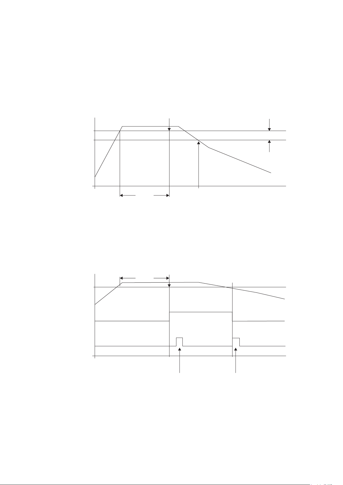
11. Alarm Output Action
Rising and Falling Non Latching Alarms
Alarm Set Point
5% of Alarm Set PointAlarm Activates
10 Seconds
(Software Adjustable)
Rising and Falling Latching Alarms
10 Seconds
Alarm Set Point
Alarm O/P On
Alarm O/P Off
Re-Set Input On
Re-Set Input Off
Alarm Resets
Alarm Activates
Indicates pressing the front
panel ‘jog wheel’ to cancel
the alarm
Page 43 of 52
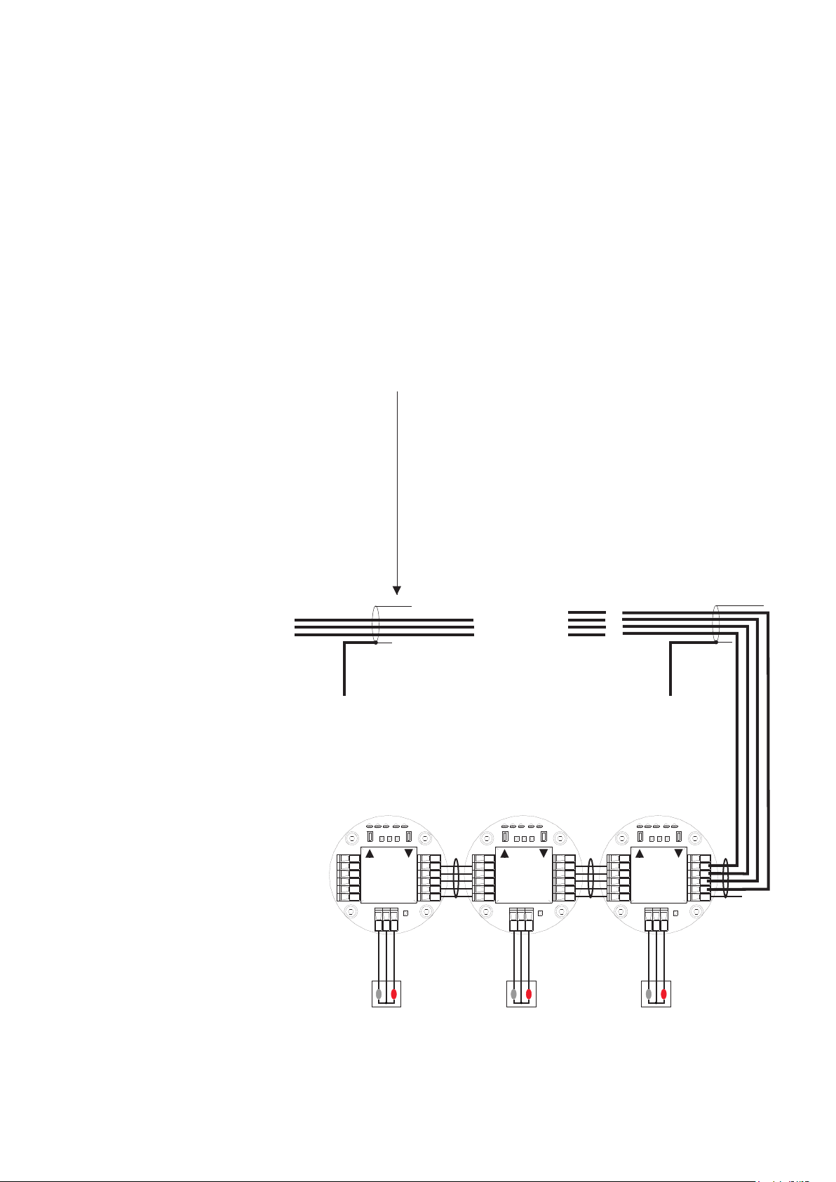
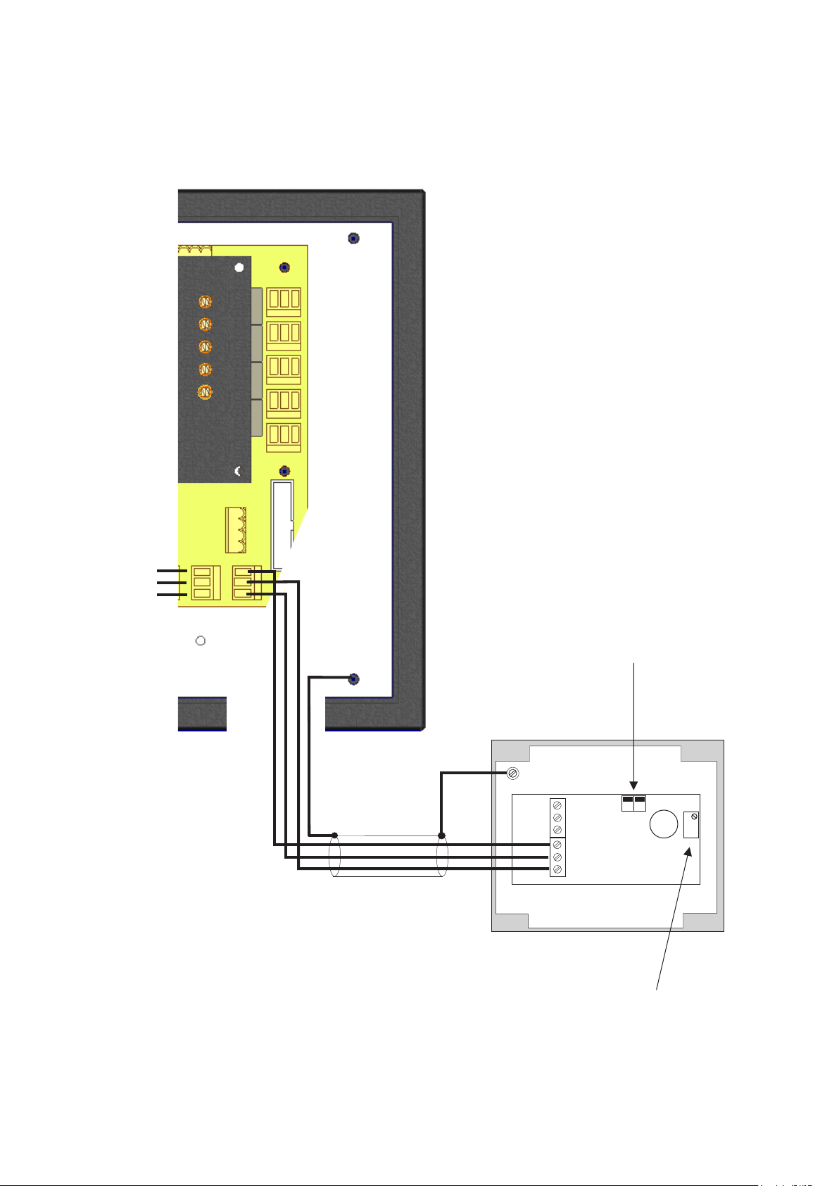
USING REMOTE ‘MIMIC’ PANELS
It is possible to connect two Tocsin 700 control panels to the same detectors. This allows you to
have the flexibility to provide local and remote display and control. The following schematic and
notes show the system requirement.
CABLING REQUIREMENTS.
Comms link between panels use min 1.5mm
SQ screened 3 core cable for up to 1KM
distance between panels. As indicated
connect A,B and GND (0V) only.
Master Control PanelMimic Panel
+24V DC
B
A
GND
Note that the detectors in this
example are communicating
with both panels (the master
panel is transparent to the
mimic). Alarms are set on the
control panel and so can be set
up to be the same or different to
meet the requirement.
+24V DC
B
A
GND
+24V DC
GND
B
A
Set C2 Remote Port as RS485 Option
Detectors Connected to Master Panel
mA+360CONC0V mA- mA+360CONC0V mA-
ZERO
CAL
360
mA
GND
A
B
24V DC
CHASS
Compensator
P Y W
Common
Active
FAULT
360
mA
GND
A
B
24V DC
CHASS
Compensator
ZERO
CAL
P Y W
Common
Active
FAULT
2.5mm SQ Cable See Previous Note
GNDGND
mA+360CONC0V mA-
ZERO
CAL
360
mA
GND
A
B
FAULT
24V DC
CHASS
P Y W
Common
Active
Compensator
Page 44 of 52
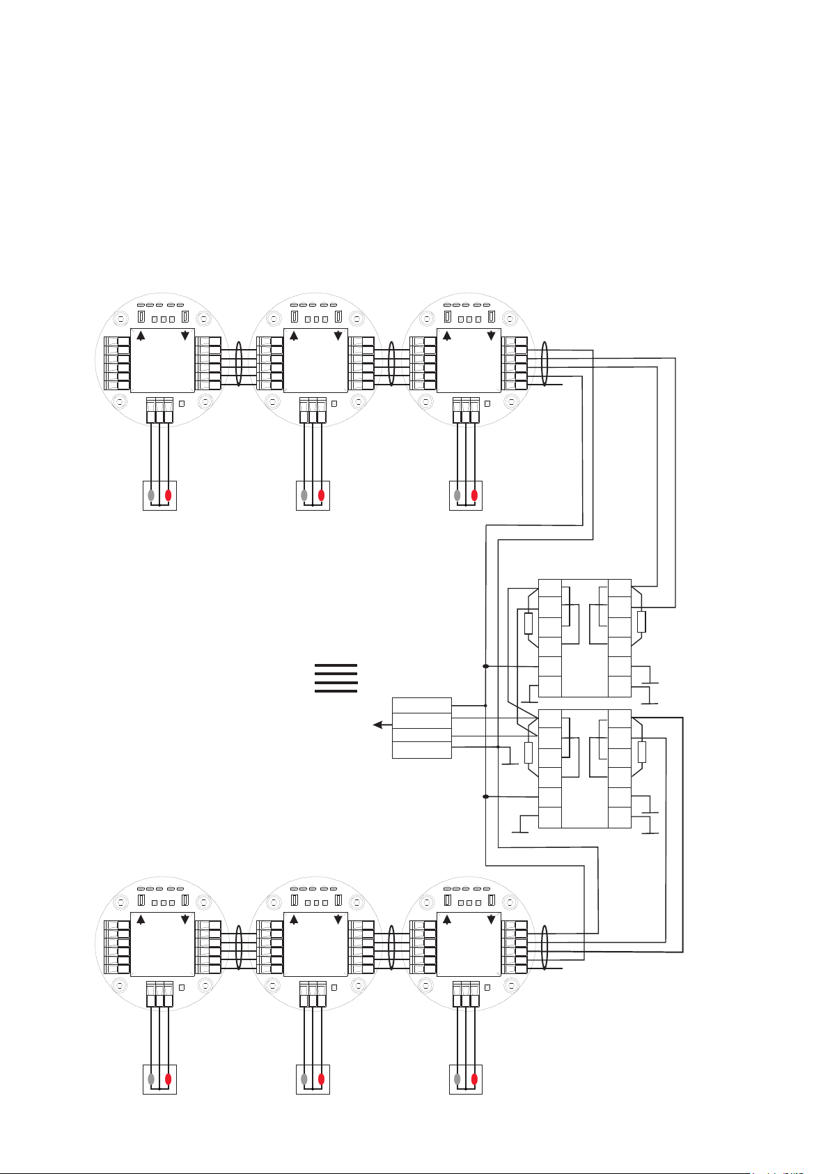
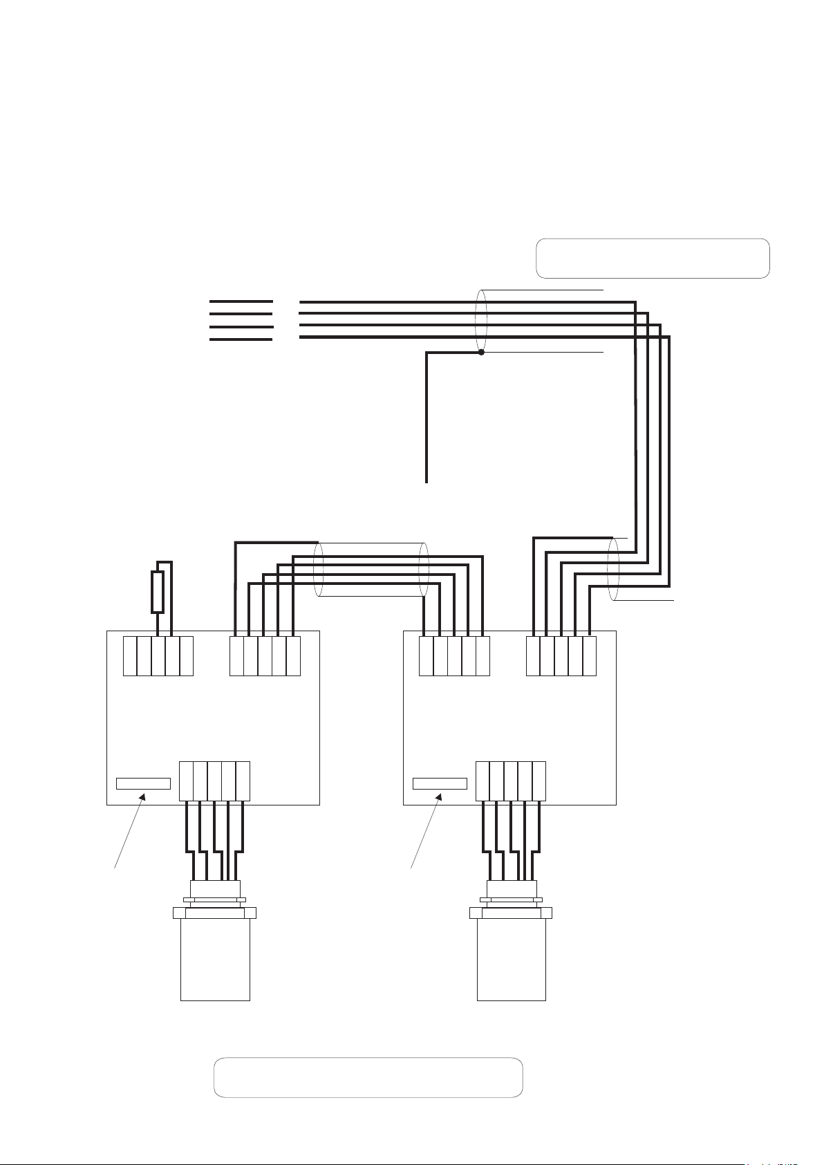
USING THE 485RPT MODULE TO SPLIT THE MAIN DATA HIGHWAY
In some circumstances more than one data highway may be required as well as a host Modbus
connection. This can be achieved by fitting 485RPT modules to the main highway port. If this is
to be implemented then one 485RPT module will be required per extra highway. The Tocsin 700
operates in the normal manner but it should be noted that there is still a limitation of 32 devices.
CABLING REQUIREMENTS.
mA+
360
CONC0V0V
mA+
360
CONC0V0V
mA+
360
CONC0V0V
mA-
mA-
mA-
mA
GND
A
B
24V DC
CHASS
W
mA
GND
A
B
24V DC
CHASS
W
Tocsin 700+ Control Panel
+24V DC
B
A
GND
+24V DC
GND
B
A
+24V DC
GND
mA
GND
A
B
24V DC
CHASS
W
G
K
H
L
J
M
B
A
G
K
H
L
J
M
D
A
E
B
F
C
485RPT
D
A
E
B
F
C
485RPT
All resistors
120 Ohms
mA+
mA-
360360
mA
GND
A
B
24V DC
CHASS
CompensatorCompensator
360
CONC
ZEROZERO
CALCAL
FAULTFAULT
PPYYW
CommonCommon
ActiveActive
mA+
mA-
360360
mA
GND
A
B
24V DC
CHASS
CompensatorCompensator
360
CONC
ZEROZERO
CALCAL
FAULTFAULT
PPYYW
CommonCommon
ActiveActive
mA+
mA-
360360
mA
GND
A
B
24V DC
CHASS
CompensatorCompensator
360
CONC
ZEROZERO
CALCAL
FAULTFAULT
PPYYW
CommonCommon
ActiveActive
Page 45 of 52

Integrated Battery Backup
The standard i700 is shipped with a 1.2AH Battery Backup Module
The battery is shipped separate from the control panel. Locate the battery in the panel once it is
mounted as indicated in the overview diagram. The batteries are shipped ready charged for
operation. Connect the battery to the charge management PCB with the cable provided
If required an additional 1.2AH battery pack can be fitted. This is supplied with a specific IGD
cable set to add the battery in parallel to the existing battery. Third party units must not be used.
additional battery module part number I700-BAT-2
Status LED’s
Note these are duplicated
on the controller front panel
DIP Switch for
Function Setup
Charge Control PCB
0V DC
12V DC
0V DC
12VDC
0V DC
24V DC
0V DC
24V DC
NC
NC
Test Points
The Single Pole relay changes state when mains power is
lost and the Tocsin 700 runs on the battery pack. It can
therefore be used to remotely indicate mains power loss.
The relay is rated at 7A 250V Non Inductive. Note the
relay is powered in normal operation and opens on alarm
or power loss.
Page 46 of 52

Front Panel Status LED’s
Mounted on the front panel of the battery backup module are two status LED’s. The Following
table indicates their operation.
The Mains power LED will be on when the unit
is operating from 110/230V AC. In this mode
the battery backup module is inactive and
being charged if required. The LED’s will
indicate the charge level as the battery is
being re-charged.
If the Mains power LED is off, then the battery
pack is active and providing backup power to
the TOCSIN 700 controller and associated
detectors. In this mode of operation the charge
level indicator LED’s indicate remaining
battery power.
The battery pack will automatically switch into
operation once the incoming 24V DC power
rail drops below 22V.
Once battery power drops below 20V DC the
controller determines that the battery pack is
exhausted and power to the TOCSIN 700
controller will be turned off.
MAINSOKBATTERY
OK
Status LED’s
> 50 % CHARGE
< 50 % CHARGE
0 % CHARGE
BATTERY FAULT
Battery Not Charging or
Battery Over Temp (>70°C)
Battery Under Temp (<0°C)
Note that the status LED’s take up to one
minute to show correct status.
Both LED’s will flash at start up as the
controller makes an assessment of the
battery and mains power status.
As soon as mains power is restored the
controller will start re-charging the battery
pack. The charge status will be indicated on
the charge LED’s. Typical re-charge time from
flat will be approximately 5 hours.
Oliver IGD Ltd reserve the right to amend product specifications in the interests of product
development and improvement without prior notice
Page 47 of 52

PCB DIP Switch Selection.
The DIP switches fitted to the charge control PCB, control
some of the operational features of the controller as
follows:
By default all switches are in the OFF position.
DIP switch 1 is used to set battery size, set to OFF for
1.2Ah batteries. Set to on for 7Ah batteries
DIP switch 2 sets the charge rate. set to OFF for max
300mA charge, this is the default max. Set to ON for
100mA charge, this setting is typically used in conjunction
with the TOC-625 controller fitted with more than 4
detectors to limit the battery charge rate due to the smaller
size of the TOC-625 PSU.
Note that the DIP switch setting is only read at power up.
The system must be powered on and off (batteries
disconnected) before the new setting takes effect.
For a new installation.
4
3
2
1
On Off
1. Connect the batteries allow system to power up on battery power
2. Switch on the mains power to the control panel
During this process observe the LED status and see the battery charge status
then the switch over from battery power only to mains and battery charge.
Page 48 of 52

Assessing A typical System For Battery Life
Use a table similar to the one indicated below to make an assessment of the system power
requirement.
System Component Alarm Mode Current Quantity Totals
Tocsin 700 0.25Amps 1 0.25Amps
Tocsin 920 0.5Amps NA NA
Tocsin 102 IR HC Detector 0.05Amps 4 0.2Amps
Tocsin 102 Pellistor HC Detector 0.13Amps 0 0
Tocsin 102 Toxic Gas Detector 0.02Amps 5 0.1Amps
Audible Alarm (Typical Example)** 0.12A 0 0
Visual Alarm (Typical Example)** 0.15A 1 0.15Amps
Additional Relay Units (8 Per Card)* 0.01A/Relay 0 0
Total System Current 0.7 Amps
The batteries used are 1.2AH units so using the previously indicated de-rating factors the
expected battery life will be as follows:-
Expected Operating Battery Life= Battery Capacity x de-Rating Factor
Total System Current
= 1.2AH x 0.75 = 1.3 Hours
0.7A
Note that in this example whilst the de-rating factor indicated was just 10% of battery capacity the
next de-rating factor up was chosen.
Values indicated in the system component table are those for alarm condition to take account of
the greatest possible current draw.
Page 49 of 52

Assessing Battery Life
Battery back up life is dependant on the power consumption of the main control panel and the
consumption of the detectors connected to it. The following table indicates how to assess the likely
back up period for a system. Other factors can have an influence particularly how many
charge/discharge cycles the batteries have been subjected to and the age of the batteries. It is
recommended that batteries are replaced every two years as a matter of course.
System Component Power Consumption.
System Component Monitor Mode Alarm Mode
Tocsin 700 0.21Amps 0.25Amps
Tocsin 920 0.38Amps 0.5Amps
Tocsin 102 IR HC Detector 0.05Amps NA
Tocsin 102 Pellistor HC Detector 0.13Amps NA
Tocsin 102 Toxic Gas Detector 0.02Amps NA
Audible Alarm (Typical Example)** NA 0.12A
Visual Alarm (Typical Example)** NA 0.15A
Additional Relay Units (8/16 Per Card)* NA 0.01A/Relay
* Additional Relay Outputs Available In Blocks Of 8 For The Tocsin 700 System And
Tocsin 920 System. Note when Making Power Assessments Only consider Active
Relay outputs.
** Examples Only Check Supplied Data Sheets for chosen Products.
Battery De-Rating Factors
It is normal practice to de-rate battery performance with increasing current draw. The
following table indicates the de-rating factors recommended to be applied in
calculating the time any given system will run on battery battery power.
Power Level Drawn De-Rating Factor
<10% 0.87
>10%<30% 0.75
>30% 0.58
Page 50 of 52

MODBUS INTERNAL MEMORY MAP ADDRESSES
Command
Function
Register
Sensor
Returned Word
Read Sensor Conc
04
30,001 to 30,999
1 to 999
Max = 1200 (110% LEL)
Min = 0 (-10% LEL)
Resolution = 0.1%
Read Sensor Volts
04
31,001 to 31,999
1 to 999
Max = 500 (5.00V)
Min = 0 (0.00V)
Resolution = 0.01V
Read Area Status
(T700 = Common
Alarms)
04
32,001 to 32,999
1 to 999
AREA
Bit4 = Sensor Disabled
Bit5 – Bit15 = Spare
Bit0 = AL1
Bit1 = AL2
Bit2 = AL3
Bit3 = Fault
Read Sensor Status
04
33,001 to 33,999
1 to 999
Bit0 = AL1
Bit2 = AL3
Bit3 = Fault
Bit4 = Sensor Disabled
Bit5 = Sensor Fault
Bit6 = Under Range Fault
Bit7 = Over Range Fault
Bit9 = Spare
Bit10 = Spare
Bit11 = Spare
Bit12 = Spare
Bit1 = AL2
Bit13 = AL1 Muted
Bit14 = AL2 Muted
Bit8 = Comms Fault
Bit15 = AL2 Muted
Mute all Alarms
051ALL
Pass = 0
Fail = 1
Reset all Alarms
052ALL
Fail = 1
Pass = 0
Disable Sensor
05
1,001 to 1,999
1 to 999
Pass = 0
Fail = 1
Enable Sensor
05
2,001 to 2,999
1 to 999
Pass = 0
Fail = 1
Zero Sensor
05
3,001 to 3,999
1 to 999
Pass = 0
Fail = 1
Set Add. Relay = On
05
4,201 to 4,232
4201 to
4232
Pass = 0 Fail = 1,2,3
(1=Timeout, 2=Already Used,
3=Not Implemented)
Set Add, Relay = Off
05
5,201 to 5,232
4201 to
4232
Pass = 0 Fail = 1,2,3
(1=Timeout, 2=Already Used,
3=Not Implemented)
FUNCTIONS:
Page 51 of 52

MODBUS INTERNAL MEMORY MAP ADDRESSES
Parameter
Setting
1: Modbus Mode
RTU Mode Only
2: Operating Mode
Slave Mode Only
#1
3: Response Time
Maximum = 100mS
(5s for Zero Command)
4: Requests
Maximum = 32 per Second
5: Panel Address
100 to 131 (100=default)
6: Baud Rate
4800, 9600, 19200 (19200=default)
7: Start Bits
1
8: Data bits
8
9: Parity
(Odd=default. None=T700 only)
None, Odd, Even
10: Stop
1, 2 (1=default & T700 only)
11: Flow Control
None
12: Physical Interface
2 Wire RS232, 2 Wire RS485
(2 Wire RS485=Optional on T900)
13: Bit Order
Least significant bit transmitted first
14: Byte Order
Least significant byte transmitted first
15: Inter-byte spacing
Maximum = 1.5 bytes times
(781uS @ 19200 Baud)
16: Inter-packet spacing
Minimum = 3.5 bytes times
(1823uS @ 19200 Baud)
COMMAND STRUCTURE
Interfacing to the Remote Modbus Port
Master DCS/BMS Master DCS/BMS
RS485 Modbus
ScreenBA
24V DCBA
Comms Port
0V DC
Note only the A,B and 0V DC
Connections are Used. 0V DC
between master and slave should be
connected for correct operation and to
prevent damage to both master and
slave systems
RS485 Modbus
Comms Port
0V DC
Modbus 485 Option Selected
Using C2 Port
1 1
Screen
Pin 2 Rx
Pin 3 Tx
24V DC
Pin 3 Tx
Pin 2 Rx
RS232 Modbus
Comms Port
Pin 5 0V
RS232 Modbus
Comms Port
Using 9 Way D Connector Port
Pin 5 0V
Modbus 232 Option Selected
Tocsin i700 Controller (slave) Tocsin i700 Controller (slave)
Page 52 of 52
 Loading...