

IGD TOCSIN 650, TOC-650-150BB, TOC-650-24, TOC-650-150, TOC-650-300 Operation And Maintenance
...
2-Wire
Addressable
Triton House
Crosby Street
Stockport
Sk2 6SH
England
TOCSIN 650 SERIES
A d d r e s s a b l e D e t e c t o r C o n t r o l P a n e l
O p e r a t i o n a n d M a i n t e n a n c e
V 3 . 1
Tel: +44 (0)161 483 1415
Fax: +44 (0) 161 484 2345
Email: sales@internationalgasdetectors.co.uk
Website: www.internationalgasdetectors.co.uk
FS646773
EMS696504
REF: T650 V3.1

Table of Contents
Specification
CE Declaration
Overall Dimensions
Interface Wiring
Highway Hub Controller Overview
Relay Card Overview
Relay Card Setup
Addressable Detector Node
Operating System
Overview
User Actions
Menu overview
Putting Into Service
New Setup Sequence
4
5
7
9
10
12
13
14
15
17
19
22
Help Section
The Sensor ZERO Function
Checking Reaction Time
The Sensor CALIBRATE Function
Troubleshooting
Standard Accessories Supplied
Accessories Available
23
25
26
27
27
28
2

Brief Introduction
The Tocsin 750 and 650 series control panels use the latest technology 2-wire addressable
highways to control gas detectors and associated accessories. Providing an extremely flexible and
low cost solution.
Main Features
750 Series
Up to 350 Detecor Nodes
Internal or External Battery Backup
2 Core Cable Connection (No Polarity)
Colour Touch Screen
650 Series
Up to 128 Detector Nodes
Cascade Panels as Master - Salve
Jog Wheel Interface
RGB Backlit Display
Service & Maintenance
It is recommended that control panels and all connected detectors are commissioned upon
installation and serviced every 6 months by an IGD trained technician. IGD can offer full training to
enable your staff to do the servicing or offer a competitive service from our fleet of service
engineers.
Warnings and Performance Statements
This product must be earthed in accordance with local safety regulations.
The Control Panel leaves the factory configured for the supply voltage stated on the customers order.
Standard options are indicated in the basic specifications on page 4
Should the control panel be used in conjunction with portable generating equipment, care should be
taken to ensure that the electrical supply is within the tolerance band described above.
The control panel may be stored at temperatures between 0 C and 55 C. If stored at low temperatures
° °
and then brought into a warmer environment, condensation may form on some components. In such a
situation , this condensation should be allowed to evaporate prior to use of the equipment. If stored at
high temperature, care should be taken to ensure that humidity condensation does not enter critical
electrical components, for example the power supply.
The Control Panel is designed to operate within specification for ambient temperature between 0 C
and 55 C, relative humidity up to 95% ( non-condensing ). Sensor specifications may differ.
o
o
Do not use a Control Panel for protection applications that has not been calibrated. If calibration seals
are missing from the control panel or have been tampered with or broken, then the control panel must
be re-calibrated and sealed by a trained engineer.
Substances and interfering gases can cause adverse effects on the performance or electrical safety of
the gas detection systems. Care should be taken to limit exposure to these poisoning substances, for
further advice and information contact head office
The response time of the entire system is determined by the time of response of all the parts of the
equipment within the gas detection system.
The relationship between the output signal and the gas concentration is linear, the control panel
interprets the signal and the gas level is displayed on the HMI or RGB backlit display. IGD hold
evidence of this linear performance which is available upon request.
We recommend users read the procedures described in BS EN 60079-29-2 for reference.

Basic Specification
150W PSU @ 110V AC Nominal
150W PSU @ 230VAC Nominal
300W PSU
Ambient Operating Temperature
Ambient Operating Humidity
Protection
Display
Displayed Detector Resolution
(Range Dependant)
Connected Hubs
Connected devices
88 to 127 V AC 50/60Hz by selection
190 to 260V AC 50/60Hz by selection
88 to 260V AC 50/60Hz by selection
0 to 55 Degrees Centigrade
5-95% RH Non-Condensing (see sensor data)
Ip54
IP ratings do not imply that the equipment will detect gas during and after exposure to these conditions.
Calibration and maintenance may be required more frequently and should be assessed based upon exposure.
2 x 8 LCD Display and Jog Wheel
1% LEL
1%Vol
0.1% Vol
1 ppm
0.1ppm
Cascade hub optional
Up to 128 Devices on single hub max 350 input channels
CE Declaration
Pressure Limits
Warm up time
Max Power Consumption
Air Velocity
EMC Compatibility
Full EC Declaration appears on Page 4
800 to 1200mBar (80 to 120kPa)
15 minutes
2 Watts
0-6M/S refer to installers guide for allowable orientation
see installer guide
4

Issuers name and address:
EC Declaration of Conformity
Oliver IGD Limited of
Declares that the product listed as:
Triton House
Crosby St,
Stockport, SK2 6SH
United Kingdom
TOCSIN 650
Addressable Gas Detection Control Panel
Are in conformity with the provisions of the following European Directive(s) when installed, operated, serviced and maintained
in accordance with the installation and operating instructions contained in the product documentation.
2004/108/EC EMC Directive
2006/95/EC Low Voltage Equipment Directive (note not applicable to 24V DC Powered Versions)
And that the standards and/or technical specifications referenced below have been applied or considered.
EN 61779-1:2000
Electrical apparatus for the detection and measurement of flammable gases, general
requirements and test methods.
EN 50271:2001
Electrical apparatus for the detection and measurement of combustible gases, toxic gases or
Oxygen: requirements and tests for apparatus using software and or digital technologies.
Excluding requirements for SIL
EN 61000-6-2: 2005
EN 61000-6-4/A1: 2011
EN 61000-3-2: 2014
EN 61000-3-3: 2013
EMC Generic standards. Immunity for industrial environments
EMC Generic standards. Emission standard for industrial environments
EMC Limits. Limits for harmonic current emissions (equipment input current ≤ 16 A per phase)
EMC Limits. Limitation of voltage changes, voltage fluctuations and flicker in public low-voltage
supply systems, for equipment with rated current ≤ 16 A per phase
Technical File Reference
T650-TF9
Oliver IGD Limited Operate an
Independently assessed ATEX/IECEX
QAN.
EMC Tested by:
TUV - SUD
Quality Assurance Certificate Number
16PQAN0014
Quality Assurance Notification Number:
2585
Units 16-18 Abenbury Way,
Wrexham Industrial Estate,
Wrexham, LL13 9UZ
United Kingdom
Oliver IGD Limited operate an independently
assessed ISO9001:2015 Quality Management and
ISO14001:2015 Environmental Management System
Certificate Numbers
FS0646773 & EMS696504
BSI Assurance UK LTD,
London, W4 4AL
United Kingdom
Octagon House
Concorde Way
PO 15 5RL Fareham
Certificate Number
E8N 15 05 91327 004
TUV Certificates and reports can be checked on-line at
https://www.tuev-sued.de/industry_and_consumer_products/certificates
Select Oliver IGD when prompted on the website to view certificates
Issued by: Oliver IGD Limited, Stockport, SK2 6SH , United Kingdom
Signature: Declaration of Conformity in accordance with EN ISO/IEC 17050-1:2004
Name: Andrew J Collier M.I.O.D
Position: Managing Director Date: 1 January 2019 Declaration Ref: T650-DEC-3

Important Notes
Gas detection systems must be correctly specified, installed and maintained in order to be effective.
Anyone undertaking elements of this work should have access to the necessary equipment and be able
to demonstrate competence. This will usually mean having passed a training competency course.
International Gas Detectors run training courses for safety survey, specification , installation and
service aspects of hazardous gas detection systems. In addition IGD can supply test equipment and
calibration gases necessary to undertake this work.
Please the following points
1. A zero grade gas usually instrument air or Nitrogen and a suitable calibration gas mixture is required.
2. The correct gas adaptors must be used to apply gases to detectors when zeroing and calibrating.
Incorrect application of gases can affect calibration results
3. Use equipment and gases traceable to a national standard. Any calibration will only be as good as
the equipment and materials used.
4. IGD supply fixed flow regulators for use with IGD calibration gas bottles which supplies gas at
0.5L/Min
Panel Options
Part Number
TOC-650-24
TOC-650-150
TOC-650-150BB
TOC-650-150B1
TOC-650-300
Description
24V DC Control Panel No Internal PSU
Standard Features inluding
2 x 8 RGB Display and Jog Wheel
4 Relays, 4 Highways
110/230V AC Control Panel 150W PSU
Standard Features inluding
2 x 8 RGB Display and Jog Wheel
4 Relays, 4 Highways
110/230V AC Control Panel 150W PSU
Standard Features inluding
2 x 8 RGB Display and Jog Wheel
4 Relays, 4 Highways
Built in 1.2AH Battery Backup
110/230V AC Control Panel 150W PSU
Standard Features inluding
2 x 8 RGB Display and Jog Wheel
4 Relays, 4 Highways
Built in 5AH Battery Backup
110/230V AC Control Panel 300W PSU
Standard Features inluding
2 x 8 RGB Display and Jog Wheel
4 Relays, 4 Highways
TOCSIN 750 Series Controller
TOCSIN 750 Series Annunciator
Options With:
Display, Relay Output, Digital or
Analogue Input, Flammable Gas Detector
TOCSIN 750 Series Detectors
Flammable Gases, Toxic Gases
Oxygen
TOC-650-300B1
110/230V AC Control Panel 300W PSU
Standard Features inluding
2 x 8 RGB Display and Jog Wheel
4 Relays, 4 Highways
Built in 5AH Battery Backup
6
TOCSIN 102 Series Detectors 2-WIRE
Flammable Gases, Toxic Gases
Oxygen For ATEX Applications

General
Note cables run with modules sequentially wired.
Power can be taken from system modules for small current devices such as LED beacon sounders and is
limited to 100mA per module
Highways are fused at 2A, observe load calculations when planning, use boosters where necessary
Observe interface requirements for relays, fitting freewheel diodes and snubbers as indicated
End of line terminators, supplied with panels must be fitted for correct operation
TOCSIN 650 PHYSICAL
360mm
Top Face
Front Face
10 off 20mm
Cable Entries
FRONT VIEW
382mm
30mm
56.5mm
20mm
292mm
2-Wire
Addressable
48.5mm
120.5mm
72mm
Side Face
134mm
Installation Cables
Supported Installation Cables 2 Core 1.5mmSQ or 2.5mmSQ See IGD Cable System Calculator
Typically SWA, MICC, FP200, SY, CY, System cables must be screened, refer to installers guide
Installation Guide
Your 750 Series control panel has been supplied with a separate installation guide. Please read this
before installing your system. The Installation guide provides information for correct cable selection,
how to correctly install cables and devices and ensure correct cable segregation. It is important to
read and understand this document prior to installation.
Copies of the installation guide are available in the downloads section of our website. Always check
you are using the latest versions of the supplied manuals by checking on the IGD website.
Failure to follow correct installation may result in poor performance and/or damage to system
components.
International Gas Detectors
2-Wire
Addressable
2-WIR E SYSTE MS
2 - W i r e G a s D e te c ti o n S y s t e m I ns t al l e r s G u i d e Vx x
OL IV ER
Triton House
Crosby Street
Stockport
SK2 6SH
England
IG D
Tel: +44 (0)161 483 1415
Email: sales@internationalgasdetectors.co.uk
Website: www.internationalgasdetectors.co.uk
Fax: +44 (0) 161 484 2345
Version 2.0
T750-INST
IGD-Academy
IGD’s On-Line training academy is available to support your companies activities. The Academy
features a range of CPD approved training courses and ‘how to’ videos.
The academy can be found at: https://igdacademy.internationalgasdetectors.com
Please note that some courses are only available on a request basis. If you require a request only
course please email to request your account and course.sales@internationalgasdetectors.com
8

T650 Control Panel & 2 Wire Hub Controller PCB Features
Rs485 Remote
Ethernet
(Modbus etc)
Battery Connection
For Battery Backup
Power in
24V DC
L2
L1
4 off 2 Wire Ports Each supporting 32 Devices
128 Devices in Total
L1
L2
L1
Display
Colour HMI
L2
Display TOC-650 (2x8 LCD)
Fault Relay
Inputs for E-stops/Fire
L2
L1
Direct Beacon-Sounder O/P
Hub cards can be cascaded to add more ports if
required. Note This is Polarity Sensitive And
Must be Connected L1 to L1 and L2 to L2.
Failure to observe polarity when cascading can
result in damage to the card
Alarm Relay 1
Alarm Relay 2
Alarm Relay 3
L1
Two display options, either 650 style with jog wheel
L2
or
HMI Style touch screen display
Note both displays can be fitted at the same time which can allow
the HMI display to be remote from the panel and used as a
system repeater or mimic

Tocsin 750 Addressable Relay Card Setting Relay Addresses
Each Addressable relay card must have its own unique base address. This can
be set on the card and is indicated below. The relays are then
addresses/numbered from that base address. The example below shows a card
with a default base address of 101
DOWN
BUTTON
108
Press and hold the DOWN button until all LED's are OFF. Release the button
and the address currently set will be illuminated on the bottom five LED’s.
Use the UP and DOWN buttons to alter the address set as indicated in the
table below
To exit press and hold UP or DOWN button until all LED’s are off then release.
1 2 3 4 5
107
106
A0A4
105
104
1 2 3 4 5
103
100
101
102
103
102
116
117
118
119
101
UP
BUTTON
104
105
106
107
108
109
110
111
112
113
114
115
NOTE: WHEN SETTING ADDRESSES YOU CANNOT HAVE TWO DEVICE ADDRESSES SET THE
SAME ON THE SAME ADDRESSABLE HIGHWAY or DEVICE.
10
120
121
122
123
124
125
126
127
128
129
130
131

Tocsin 650/750 Addressable I/O Card
Power out for
use in
conjunction
with relays
0V DC
24V DC
In all Cases:
Relay contact ratings.
5A @ 250V AC Non-Inductive
5A @ 30V DC Non-Inductive
Spike suppression must be fitted
Note that FAULT relays are normally
energised on power up.
Relay status LED,
ON when Energised
10 off I/O Ports
2-Wire Highway Connections
Pin 1 Line 1
Pin 2 Line 2
24V DC
A2
A1
Example fit
protection
diodes when
0V DC
switching
external DC
loads.
~
A1
~
A2
Example fit protection
supressors when
switching external AC
loads typical device
Farnell Ref 1438460
Pin 1 Line 1
Pin 2 Line 2
Base Address set up
LED's and interface
for the relay card
Normally Closed
Common
Normally Open
Relay Terminals
First Relay on
The Card (relays
number from
this one).
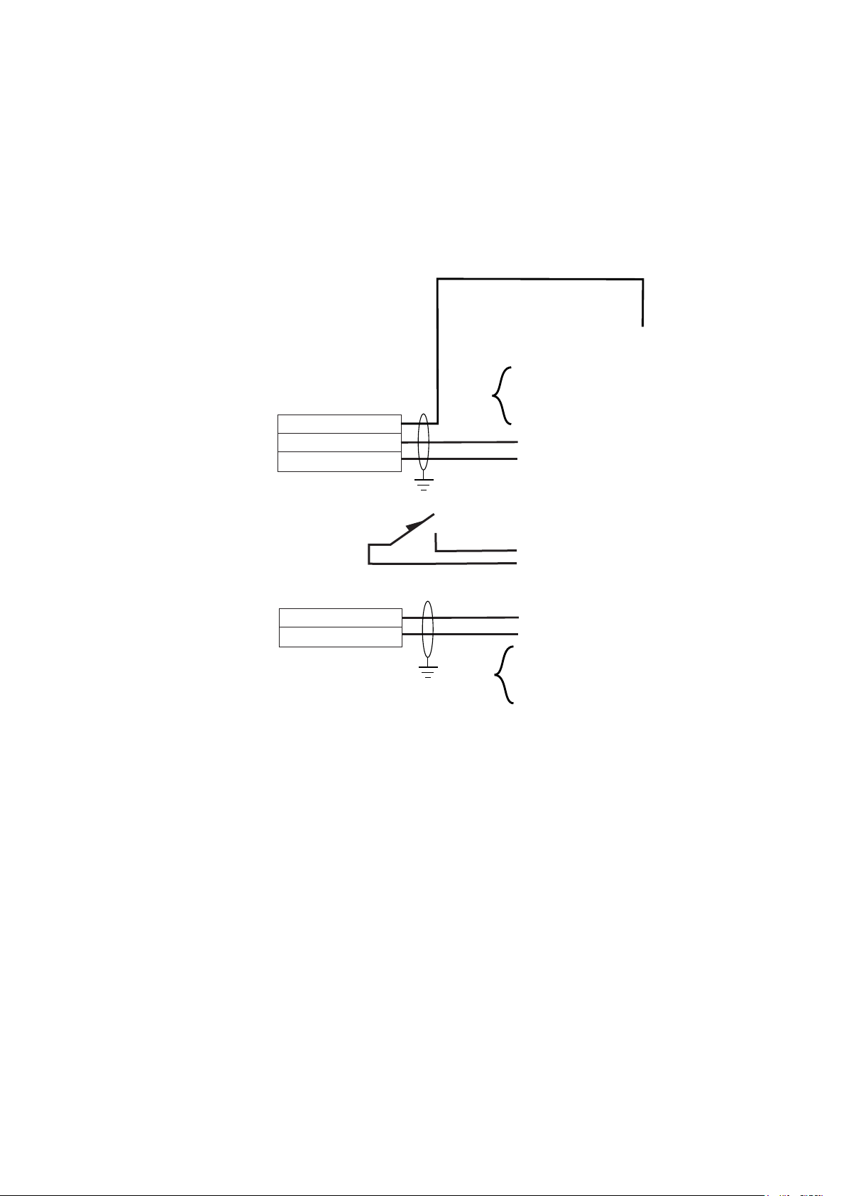
Tocsin 650/750 Addressable I/O Card Input Ports
Relay cards also have analogue and digital inputs that can be used to read data onto the system
from external devices. Setup of the inputs, type, range, addressing etc is controlled via IGD’s
Android Apps. Wiring options are indicated below. Note the differences between Version 1 and 2
PCB assemblies.
Typical IGD Loop Powered
4-20mA Detectors
Pellistors Based Detectors
Infra Red Based Detectors
PID Based Detectors
Thermal Conductivity
Typical IGD Loop Powered
4-20mA Detectors
Temperature
Pressure
CO
H2S
Oxygen
HCN
HCL
NO
NO2
H2
CL
SiH4
O3
3 Wire Detectors
0V DC
4-20mA Signal
24V DC
Loop Powered Detectors
4-20mA Signal
24V DC
Note 1
Note 2
10
9
8
7
6
5
4
3
2
1
Note 1
Note 2
Note 3
These Ports are designated to be digital inputs only.
These Ports are not used on version 1 PCB assemblies limiting the PCB to a maximum of 6
analogue inputs or 8 digital inputs including ports 9 and 10.
If extended 4-20mA devices are connected, they maybe floating ground type.
12

Module PCB Features
The following diagram indicates features available on the TOC-750 ‘module’ PCB. Please note
that failure to observe and make correct connections or exceed ratings may result in damage to
the PCB.
6
5
Ribbon Cable Connection For TOC-750
Annunciator Display and Options
Pellistor (Catalytic)
Flammable Gas
Connection Point For
IGD Infra-Red, Toxic, PID
or Oxygen Gas Detectors
Multi-Function I/O Port 2
Solid State Output or
4-20mA Input or
TOC-10 IP or Gas Meter
P
7
Y
W
3 3
Detector Interface
Suitable for IGD
4
Types MK3, MK6, MK7
Multi-Function I/O Port 1
Solid State Output or
4-20mA Input or
TOC-10 IP or Gas Meter
2-Wire Highway
Connection
1
To Next Device
DVM Test Point +
SPCO Relay
Output
2
And Up/Down Interface Buttons
Module PCB Basic Interface Specifications
Housing
Sealing
Environment
Temperature
Voltage
Communication
1
Relay
2
Digital Output
3
Digital Input
Analogue I/P
Pellistor Port
4
Sounder
5
Display
6
Comm Port
7
TOC-750 Series ABS or Copper Free Aluminium For ATEX Versions
IP65 (using suitable glanding & splash guard) for TOC-750, IP68 for ATEX Versions
0 -95% RH Non Condensing
0-55 Deg C
12-28V DC
IGD 2-Wire Highway Operating IGD Sentinel+ Protocol
Not Polarity Dependant
5A Non Inductive Loads 230V AC
24V DC 100mA Combined For Both Outputs Typically for LED Beacon Sounders
Suitable for use with TOC-10 Link Function, switch/call point, totalising count
4-20mA, selectable range, units and tag information
Option to Interface to MK3, MK6 or MK7 Pellistors
85dB (Option for TOC-750 Annunciators)
2 x 8 Programmable LCD with RGB Backlight (Option for TOC-750 Annunciators)
Supports IGD Infra-Red, PID, Toxic and Oxygen Gas Detectors
Local LED Indications
1
2-Wire Highway
Connection
To Next Device
DVM Test Point -

User Actions....Day to Day Operation
Once fully installed the TOC-650 controller will continuously monitor connected gas detectors and
sensors and compare current values with any set alarm thresholds. The display will cycle to display
each channel in turn.
To access the display and switch the backlight on rotate the jog wheel
Channel
Number
The back light turns on making
it easier to see the channel
information. Note that each
channel will be displayed in turn
as indicated by rotating the jog
wheel
In Alarm Condition
Alarm Level
The back light will flash red and
the display will indicate which
alarm level and which channel
is in alarm. The sounder will
also activate. Pressing the
button will silence the sounder.
If the gas is still breaching the
alarm threshold it will not be
possible to reset the alarm
Channel
Number
Gas or Reading
Type
1=FLAM
10% LEL
Current Channel
Reading
Channel
Gas Type
1=FLAM
alarm 1
In the event of alarm or fault, CALL FOR SERVICE.
The owner operator is not usually a gas engineer or competent person
as defined by Health and Safety guidelines. If there is any doubt call
your service company and get it checked.
In alarm mode the RED
alarm led will either be
flashing for alarm level 1 or
solid for alarm level 2. The
bottom line of the display will
indicate:
Alarm 1
Alarm 2
Alarm 1&2
In Fault Condition
In FAULT mode the Yellow fault led
will be on. The bottom line of the
display will indicate as follows:
FLT COM
FLT SEN
FLT OVR
FLT UND
communication
error to sensors
Sensor Error
Sensor Over Range
Sensor Under Range
Channel
Number
Channel
Gas Type
1=FLAM
FLT UND
14

Controller Interface Overview
Internal Sounder 85dB
Sounds on alarm 1 or 2 activation
and can be muted
Colour Backlit LCD Display
Flashes Red on alarm
Flashes Yellow on Fault Detection
Blue during menu operation
.
Alarm Indicator LED (Red)
Flashes on Alarm Level 1
Continuous on Alarm Level 2
Fault Detected
Indicator LED (Yellow)
Typical display during warm up
WARMUP
600s
Selector Button
Power LED (Green)
Selector Jog Wheel
• Initial power up sequence is:
o Indicate board tested status (end
user should see “PASSED” with a
green backlight)
o Display then shows Software
version, Checksum and date,
Display version, display
checksum and date, connected
sensor info
o Countdown

To Access the Display rotate the Jog Wheel
Channel
Number
Gas or Reading
Type
1=FLAMM
10% LEL
Current Channel
Reading
Data entry and menu selection using the password entry as an example.
To access the menu system press the button until the message
“Release button and enter password”
message is displayed.
Password Number You are
Entering. Rotate the jogwheel
clockwise to increment or
Anticlockwise to decrement
0
PASSWORD
With the correct password displayed
press the centre selection button
to go to the menu or function.
25
PASSWORD
INHIBIT USER MENU
Inhibit the control panel for
up to 60 minutes. Use this
option if calibrating or
accessing the connected
devices using a laptop
running IGD Configurator
software. Inhibiting the panel
means it stops
communicating to connected
devices this prevents alarms
or data clashes during PC
access.
50
PASSWORD
CALIBRATIONS & ALARMS
Zero and Calibrate Sensors.
Setup alarm levels and relay
actions.
16
100
PASSWORD
ENGINEER MENU
PANEL TEST & SETUP
Test I/O Functions, FIND
connected devices. Setup
channels, Modbus addressing etc.

TOC-650 Menu Overview
0000
PASSWORD
50
Engineer Menu Options
Provides access for control panel
set up and diagnostic functions
FIND SEN
1 of 12
FIND RLY
2 of 12
DIAG
3 of 12
SET TIME
4 of 12
SET DATE
5 of 12
SEN mS
6 of 12
RLY mS
7 of 12
CASCADE
8 of 12
Use this option to
FIND connected Input
devices.
Use this option to
FIND Relay Outputs.
Use to Access Device
Diagnostics
Set the System Time
Set the System Date
Use to check the comms
response time for sensors.
Should be less than 10mS
Use to check the comms
response time for relays.
Should be less than 10mS
Use to set hub cascading
options
100
User Menu Options
Provides access for
maintenance functions
ZERO
1 of 9
cal
2 of 9
DISABLE
3 of 9
CONTRAST
4 of 9
VIEW EV
5 of 9
CLEAR EV
6 of 9
SEN INFO
7 of 9
Use this option to
ZERO connected
devices
Use this option to
CALIBRATE
connected devices
Disable a Device
Use this option to set
the screen contrast
Select to View the
Event Log
Select to Clear the
Event Log
Select to View
Information About a
sensor
TEST RLY
9 of 12
BL. TOOTH
10 of 12
USR MENU
11 of 12
EXIT
12 of 12
Use to Energise/Deenergise relay outputs
Use to enable/Disable
Reset Bluetooth
Move to the USER
(100) Menu
Select to Exit Back to
Normal operation
ABOUT
8 of 9
EXIT
9 of 9
Use to View Software
Versions
Select to Exit Back to
Normal operation

TOC-650 Menu Overview
Provides access for control panel
set up and diagnostic functions
0000
PASSWORD
345
Production Menu Options
RESET
1 of 8
SET DFLT
2 of 8
DISP TST
3 of 8
Z CVolts
4 of 8
Z BATTERY
5 of 8
USR MENU
6 of 8
ENG MENU
7 of 8
Use this option to
Reset the Hubcard
(System Re-boot)
Reset Hubcard to
defaults
Display Self Test
Not Used
Not Used
Use to Move to the User
(100) Menu
Use to Move to the
Engineer (50) Menu
EXIT
8 of 8
Exit to Normal
Operation
18

Putting Into Service
Note that this product should be supplied via a fused spur. Ensure cables used are suitable for both
their intended area of operation and load capability. This product should only be installed by a
competent person.
Follow the 2-Wire Installation guide
This provides location as well as cabling/installation guidance.
Failure to observe correct installation can have an adverse affect on system operation
and performance
if you don't have a copy of this download it from www.internationalgasdetectors.com
To set alarm levels and programme the required cause and effect you will need to
access the controller using IGD’s Panel Setup App for Android. Download the Panel
Setup App from the Google Play Store to a suitable blue tooth enabled tablet or
Phone. Android 4.1.1 or later operating system and min 7” display recommended.
It is recommended to follow the set up sequence below when configuring and installing a control
panel from new.
Note panels are usually supplied pre-configured so this many not be necessary, check
shipping documentation
Perform a sensor FIND and automatically install detector data. Engineers Menu .... Find Option
find sen
1 of 12
Perform a Relay FIND
find rly
1 of 12
With Sensors and Relays Installed download the panel setup to IGD’s Panel Seup App to configure
the system. It will be necessary to upload this once completed and re-start the controller for it to take
effect.
Allow the system to run for at least an hour to allow detectors to fully stabilise to the site conditions.
Detectors are supplied pre-calibrated. Follow the Bump Text video on the IGD online Academy to
check both detector calibration and to prove the system programmed cause and effect. Ensure all
interfaces to third party devices and systems function as required. Note that individual relays can be
directly energised and de-energised to aid checking
TEST RLY
9 of 12
Should any detectors require re-calibration
zero
Zero each connected detector. User Menu ZERO
1 of 15
cal
Calibrate each detector. User Menu CALibrate
2 of 15
Ensure there are no indicated system errors in normal operation.
Note IGD calibration and gas adaptor kits are available and necessary to perform calibration and
bump testing. Record all results for traceability.
If you are uncertain how to zero/calibrate or locate your gas detectors and system components then
use IGD’s online training academy.
If your application is safety related you must ensure you are a competent person with demonstrable
training. If in doubt check with IGD for help and support.

Warm Up Period
With power applied the system should undertake its power up sequence and
then commence a warm up period. The warm up period is there to allow
connected detectors to stabilise before operation. Note that certain detector
types, Oxygen sensors in particular may take up to 2 hours to fully stabilise.
During the warm up period check that each connected detector or device has power and
communication. The following diagram shows the three main terminal PCB types for detectors and I/O
interface nodes and the relevant check points.
With sensors connected and after the TOC-650 controller has completed its warm up the operating
system will go to normal operation mode.
Normal Operation
In normal operation mode the TOC-650 communicates to each detector or node in turn and displays the
data on screen. Pressing the button once will activate the back light, each button press then cycles the
display through each channel.
For example a three channel system with a Flammable gas detector, a Carbon Monoxide Detector and
WARMUP
600s
an Oxygen detector would read as:
Channel Number Gas Type
1=FLAM
0% LEL
Reading Units
2 = CO
0 ppm
3 = O2
21% VOL
20

Putting into Service Test Schedule
In conclusion by following the steps discussed your checklist for putting into service should be:
1
Ensure the mains power supply is via a fused spur and installed in accordance with local
installation wiring regulations.
Check cable and glands are of suitable type for both the area of application and load carrying
capacity.
2
Ensure terminations via glands provide a positive seal.IGD Gland packs PN TOC-GLAND
achieve minimum requirements when correctly installed
Leave all interfaces unplugged and check installation cabling terminations following IGD 2-Wire
3
Installers Guide, check website for latest revisions.
4
Check the shipping TOC-650 SET UP REPORT to check how the controller and interfacing
detectors and nodes have been configured. Ensure that the detector addresses match the
document and required site locations.
Power up the system. Check that all connected devices indicate that they have power and are
5
communicating correctly.
Allow at least 1 hour for the detectors to correctly warm up and stabilise.
6
During this period, if the relay outputs are being used check the cabling then plug in and test
using the TST RLY function.
7
After warm up is complete use instrument air or Nitrogen as appropriate to check the detector
zero reading. Adjust if necessary (see later “zero and calibration function” section).
8
After warm up is complete use a suitable known calibration gas to check the detector calibration
reading. Adjust if necessary (see later “zero and calibration function” section).
9
Bump Test to check programmed cause and effect operates as required
10
Complete any site paperwork as necessary and instruct the site responsible person regarding
day to day operation (see later section “ user operation “).
11
Download the controller setup and save as a backup for the system.
In the event that the controller needs amendment to set up follow the instructions in the following
sections.
a) Adding detectors or nodes to the controller or complete set up
b) Adding or changing alarm levels
c) Assigning relay outputs
d) Zero and Calibration Function (detectors)
e) Zero and Calibration Function (analogue output)

Sequence for a Complete New Setup
If you need to perform a complete new set up
Then presuming the system is correctly installed and cabled the process would be as follows:
1. Use the FIND command to discover connected devices and install them to the controller
2. Set up the required alarm levels and relay actions
3. Test using zero and calibration gases
The following dialogues describe each function to use
The FIND Command
As previously described enter password mode and enter password 50 to gain access to the
engineers menu. The first menu option (menu option 1 of 11) is the FIND menu. To run this option
the detectors must be correctly connected to the controller and displaying green power LED function
as a minimum (some of the green power LED’s may be flashing if detectors already have
communication.) The FIND function then works in the following manner
find
1 of 11
1
Press and hold button
until prompted to
release. The system
starts discovering
connected devices
find
Release
When the discovery process is
complete the display indicates
how many sensors have been
found. The system also indicates
the first found address. Each
button press then indicates each
found device address in turn.
find
1 of 11
s=2 40%
checking
2
Display indicates devices found so far
Display indicates % progress
1 = 4101
found= 2
2 = 4101
found= 2
2 = 4101
Release
no
Release
3
To store or abort the data press and
hold the button until prompted to
release. The first option is NO to
store data, rotating the jog wheel
changes this to YES to store data
and vice versa. With the desired
option displayed press the select
button.
yes
Release
saved=2
passed
4
If the YES option to store data
was selected then the number
of saved devices is shown on
screen and passed of fail to
indicate the status of the
update
If the control panel has been shipped pre-configured then once correctly connected the system will be
operational. The controller should correctly cycle through each channel with no indicated errors.
Relay Test
The alarm relay outputs can now be connected (if they are being used). The relay outputs can be
forced on and off using the ‘test relay’ function (TEST RLY).
test rly
13 of 12
22

Gas Detector ZERO Function
All gas detectors will require periodic ZERO and CALIBRATION. The calibration interval depends on a number of
environmental factors such as: temperature variance, exposure to wind chill, rain, humidity changes and vibration
to list a few. As a guide line gas detectors should be checked at least yearly. As with any measuring instrument if
calibration is not held over the intervening interval then a shorter calibration interval may be required.
Detectors should always be zeroed first and then calibrated. Alarms should be isolated during this process. A
normal calibration sequence would consist of:
1. Assess zero reading in pre-zero condition and record by applying a zero gas typically Nitrogen or Instrument air
2. Assess calibration point by applying a known calibration gas. and record
3. If the zero and calibration points are within +/-2% of range then take no further action. zeroing and calibrating a
detector that already reads correctly will not improve its performance. If either is out then proceed to step 4.
4. Apply a suitable zero gas and zero the channel, observe and record result.
5. Apply a known calibration gas and calibrate the channel, observe and record the result.
Notes
Do not rely on the ambient environment to provide a zero point, Nitrogen or Instrument air should always be used
as appropriate. If there is a background level of the target gas and a zero is performed then the zero point will not
be correctly set.
This sequence first indicates
To Zero the detector enter password mode
as previously described and enter
password 100 to enter the user menu.
Select menu item 1 ZERO
zero
1 of 10
The top line of the display shows the
if the zero operation passed
or failed, then the new
detector reading then the
option to end and return to
the engineer menu. This
sequence effectively allows
the engineer to observe the
new detector zero point
before exiting.
Regulator to deliver a
fixed flowrate (typically
between 0.5 to 1 L/min)
current reading. The bottom line shows the
current option.
8 PPM
Abort
With zero gas flowing and the reading stable
press the button to select CONTINUE. Now
press and hold the button until prompted to
Zero
Gas
Calibration
Gas
20% LEL
Hose delivers zero gas to the
detector. Note a test gas
applicator is usually required.
In some cases weather
protection guards or the
detector itself may include a
gas applicator port. If not the
correct calibration gas
adaptor must be used.
release to action the zero request.
0 PPM
Continue
ZERO
PASSED
0 PPM
CLICK TO
Bottled Nitrogen or Instrument grade zero air
The display shows the result of the zero request, note that the actual zero and
calibration values are stored on the individual detector heads. When carrying out a
zero or calibration the controller sends the request to the detector head for action
and monitors the result. This means that detectors can be supplied pre-calibrated
The reading is now displayed so the result of the zero request can be observed.
The reading should be stable. Click the button to return to the previous menu.
Repeat the sequence if you are not within +/-2% of zero.

The Sensor ZERO Function
Zero and calibration functions should only be undertaken by trained competent
personnel. The effectiveness of a gas detection system is largely down to how well it is
maintained and this means how well it is calibrated.
Apply zero gas to the detector.
It is important that the detector zero point is correctly set. It must be considered that
there is the possibility that the gas to be detected is already present in the area of the
detector. For this reason never zero on just the ambient surroundings.
There are two possibilities
A. confirm there is no gas present by using a portable detector
B. Use a suitable ZERO gas as follows.Zero gas should have a humidity between 0-90%RH
GAS RECOMMENDED ZERO GAS
O2/CO2 NITROGEN
PELLISTOR INSTRUMENT AIR
TOXIC GASES NITROGEN
The following diagram shows a typical equipment set up.
Regulator to deliver a fixed flowrate (0.5-1 L/min)
Oliver IGD P/N 5022001
Recommended Test 750 series Gas Applicators.
Tocsin 102 Series Detector P/N 401101A
MK3 Gas Detector P/N 401101A
Cal Gas Adaptor
Ensure it is correctly
fitted
ZERO
MK5 & MK6 Gas Detector P/N 401101E
TOC-750 Series
GAS
Hose delivers cal gas to the detector. Note a test
gas applicator is usually required. In some cases
weather protection guards or the detector itself
may include a gas applicator port.
Relative response to Methane @ 4.4%
Vol = 100% LEL
Equivalent to 55% LEL N-Butane
IMPORTANT: Flow gas for a minimum of 60 Seconds. Some detectors with longer response
times may take longer to stabilise.
Procedure for check reaction time to gas
Use standard IGD professional gas introduction kit with 2M hose.
Using a stop watch turn on the calibration gas and time to 50% and 90% LEL
Note on a 20% LEL bottle T50 point is 10% LEL and T90 point is 18% LEL
on a 50% LEL bottle T50 point is 25% LEL and T90 point is 45% LEL
Ensure detector is at zero +/- 1% LEL
Connect calibration gas but do not turn on
Time to 50% should be less than 30 seconds
Time to 90% should be less than 60 seconds
replace non conforming sensors
24

Once the alarm level has been set you then need to set the Alarm TYPE and decide which relay activates
once the set alarm level is breached. The following sequence continues from the previous page and
describes the set up sequences
Scroll to change selection
LEVEL TYPE RELAY EXIT
To select an option rotate the jog
wheel and press the selection button
to select the required option
Top line indicates “select alarm type” Rotate
the jog wheel to select the desired alarm type
option. Press the selection button to select.
RIS LAT RISING FALLINGFALL LAT
Rising Latching Alarm
Latching alarms
remain set until the
button is pressed to
reset the alarm. The
gas level must be
below the alarm level
threshold for the reset
to operate. This type of
alarm is typically used
in safety applications.
Where alarm is
required in response to
rising gas levels
Rising Alarm
Rising alarms will
automatically reset
once the gas level falls
below the alarm
threshold. This type of
alarm is typically used
in control applications
where action is
required in response to
rising gas levels.
Press and hold until
prompted to release to
Falling Latching Alarm
Latching alarms remain set
until the button is pressed
to reset the alarm. For a
falling alarm the gas level
must be above the alarm
level threshold for the reset
to operate. This type of
alarm is typically used in
safety applications for
Oxygen deficiency
monitoring where you are
monitoring for a falling
Oxygen level.
select this option.
Press and hold until
prompted to release to
select this option.
Press and hold until
prompted to release to
select this option.
Select Alarm TypeSelect Alarm TypeSelect Alarm TypeSelect Alarm Type
Falling Alarm
Falling alarms will
automatically reset once
the gas level rises
above the alarm
threshold. This type of
alarm is typically used in
control applications
where action is required
in response to falling
gas level (typical in
Oxygen deficiency
applications).
Press and hold until
prompted to release to
select this option.
Rising and Falling Non Latching Alarms
Alarm Set Point
10 Seconds
If alarm devices, output contacts or alarm signal outputs are provided as part of continuous duty
gas detection equipment and are intended to operate when a potentially hazardous gas
concentration is detected, they shall be of a latching type requiring a deliberate manual action to
reset. If two or more alarm set points are provided, the lower may be non-latching - based on user
preference. Alarms shall remain in operation while the alarm condition is still present, although
audible alarms may be silenced if this audible alarm is not the only alarm.
Alarm Resets
Rising and Falling Latching Alarms
5% of Alarm Set PointAlarm Activates
Alarm Set Point
Alarm O/P On
Alarm O/P Off
Re-Set Input On
Re-Set Input Off
10 Seconds
Indicates pressing the front panel ‘jog wheel’
Alarm Activates

Gas Detector CAL Function
Gas detectors must be calibrated with known calibration gases traceable to National Standards. As previously
discussed detectors require regular calibration. Calibration gases should have values chosen that either:
a) Are at the alarm set point to get maximum accuracy at this point
or
b) Are between 50 to 90% of the range of the detector. The detector measuring range will normally be marked on
the detector.
To CAL the detector enter password mode
as previously described and enter
password 100 to enter the user menu.
Select menu item 2 CAL
CAL
2 of 8
Enter the channel number you wish to
calibrate.
1
sensor
Enter the calibration gas value, this will be
marked on the gas bottle and enter.
50
BOTTLE
The top line of the display shows the current
reading. The bottom line shows the current
option.
55 PPM
Abort
With CAL gas flowing and the reading stable
press the button to select CONTINUE. Now
press and hold the button until prompted to
release to action the zero request.
This sequence first indicates
if the zero operation passed
or failed, then the new
detector reading then the
option to end and return to
the engineer menu. This
sequence effectively allows
the engineer to observe the
new detector zero point
before exiting.
Zero
Gas
Bottled Nitrogen or Instrument grade zero air
Calibration
Gas
20% LEL
Regulator to deliver a
fixed flowrate (typically
between 0.5 to 1 L/min)
Calibration gas.
Note: the concentration marked on
the label. Ensure it is of the correct
type for the detector being
calibrated. The concentration
should typically be 50 to 90% of
the detector range.
Calibration gas should have a humidity between 0-90%RH
Refer to EN 600179-20-1 for gas concentration guidance.
55 PPM
Continue
CAL
PASSED
50 PPM
CLICK TO
Repeat this sequence if you
are not within +/-2% of the
gas bottle value.
The display shows the result of the cal request, note that the actual zero and
calibration values are stored on the individual detector heads. When carrying out a
zero or calibration the controller sends the request to the detector head for action
and monitors the result. This means that detectors can be supplied pre-calibrated
The reading is now displayed so the result of the cal request can be observed. The
reading should be stable. Click the button to return to the previous menu.
26

Troubleshooting
Fault of electric circuit Please contact IGD
Warm up is not finished Wait till warm up is finished
Sensor is overdue service
and calibration
Please contact IGD for
service and calibration
Possible fault
Possible reason
Possible solution
The detector cannot
be turned on
No power supply
Connect power supply
Panel failure
Please contact IGD
No response to the
gas
Electrical Fault
Please contact IGD
Inaccurate indication
Damaged sensor
Please contact IGD
Sensor fault indication
Sensor fault
Please contact IGD
Fault indication
Error Message
Reboot system
Error Message after reboot
Please contact IGD
Minus gas level
displayed
Gas sensor drift
Calibrate zero point
Standard accessories Supplied
1 x Terminator Set (5 off)
1 x Resistor Pack
1 x Diode Pack
1 x Snubber
Battery Care
For control panels with the internal battery backup the following battery care is recommended:
Installation: The batteries will come pre-installed but will be disconnected to prevent battery drain.
They should be connected before the panel is connected to the mains supply.
Maintenance: Batteries should be checked at each 6 monthly service visit to ensure full
functionality. Batteries have a life of approx. 5 years dependant upon usage.
Battery Backup units and Power Booster units are available.
Recommendations for maintenance after measuring range is exceeded
Allow to stabilise in clean air or use instrument air at 0.5L/Min for 4 hours. If reading is greater then
5% LEL after this period replace otherwise re-zero and calibrate

Accessories
Part Number Description
5083101 Beacon Sounder Amber/Red
508150 Beacon Sounder Red
5083160 Beacon Sounder Blue
401101B Cal Adaptor (Tocsin 103)
401101Z Cal Adaptor (Zirconia)
401103 Cal Adaptor (MK5/6)
4011109 Gas Adaptor (TOC-30, TOC-10)
401451 Splash Guard (Tocsin 103)
401452 IGD Splash Guard
401465 Protection Filter Disk
5110101 Remote Gassing Port
5134601 40mm Stop Button
5138601 Collector Cone Ring Lock
5138701 T103 Splash Guard
5138801 `Collector cone kit (MK6)
TOC-GLAND M20 Snap fit cable glad
5925801 Universal Pole Clamp
TOC-750-DIO Free wheel diode pack
TOC-750-HMI Remote HMI display
TOC-750-IO2 8 Channel Relay Card
TOC-750-SNB Contact Suppressor (Snubber)
TOC-750-TRM Terminator set
TOC-GAS-KIT Bump Test Kit
5137201 Professional Calibration Kit 1
5142301 Professional Calibration Kit 2
5124601 Professional Calibration Kit 3
28
 Loading...