

Page 1

2 - W i r e G a s D e t e c t i o n S y s t e m I n s t a l l e r s G u i d e V 4 . 5 1
Triton House
Crosby Street
Stockport
SK2 6SH
England
2-Wire
Addressable
2-WIRE SYSTEMS
Tel: +44 (0)161 483 1415
Fax: +44 (0) 161 484 2345
Email: [email protected]
Website: www.internationalgasdetectors.com
FS646773
EMS696504
REF: T550-INST V4.51
Page 2

2-WIRE
GAS DETECTION
Display
Analogue in
or
Digital Out
&
Sounder
Gas
Detector
2-Wire
Addressable
HUB
Gas
Detector
Each Detector Node Has Multiple I/O
APP Based Setup and Service Tools
2 Core Cable Connects Detector Nodes
No Specific Cable Type
No Cable Polarity
350 Detector Nodes/Devices Possible
Communicate over 3000M Possible
Cascade Hubs or Control Panels
Modbus and Bacnet Compatible
Battery Backup
BlueTooth
Ethernet
Volt Free
Relay
Output
Analogue in
or
Digital Out
First Fit Cabling
Fit Detector Nodes
Fit Additional Devices
Where You Need Them
CO
Safety Assured
FS646773
USB
ALL
OK
H2S
www.internationalgasdetectors.com
LPG
1
4-20
Page 3

Introduction
This installers guide is intended for the use of system specifiers, surveyors, designers and installers.
The intention of this guide is to provide information for the correct installation of IGD’s range of 2-Wire
gas detection systems. This guide indicates correct cabling practice, types of cabling which can be
used and options available to correctly design and install a 2-wire gas detection system. This guide is
not intended as a design or specification guide, these are available separately.
Note that System control panels, detector nodes, battery backup modules and power boosters are all
supplied with their own manuals. Their general specifications and performances are available both in
their individual manuals and published data sheets. This data is not reproduced in this guide.
Failure to follow this installers guide could compromise operation of the 2-Wire gas detection system
so please follow the enclosed information carefully.
Systems should be designed and installed by competent persons. A competent person being defined
by the UK Health and Safety Executive as:
A competent person is someone who has sufficient training and experience or knowledge and other
qualities that allow them to assist you properly. The level of competence required will depend on the
complexity of the situation and the particular help you need.
IGD’s gas detection systems are capable of installation by electrical installation engineers. Design of
a system is not covered in this guide and should be undertaken by a competent person. The design
should include:
The Nature of the Gas Hazard and Appropriate Placement of Detectors
Clear Indication to workers That a Gas Hazard Exists and the Action They Must Take
Interaction Between the Gas Detection System and Other Systems
The Necessary Safe Operating Procedures That Must be in Place
IGD can provide help to design systems where help is required and can also provide training for
surveyors, specifiers, designers and installers.
All Gas Detectors shipped from IGD are pre-calibrated. It is not always necessary to re-calibrate a
newly installed system on site but it is recommended that commissioning is undertaken.
Commissioning should be undertaken by persons trained to do so. Commissioning should ensure that
the system performs and interfaces correctly to all connected devices, host systems and operates to
the required cause and effect.
IGD are available to answer question using our on-line ticketing system available through our website.
NOTE that ATEX equipment has specific requirements for cable protection and glanding to housings.
These requirements are detailed in manuals for such equipment available through our website.
2
Page 4

SECTION 1
MOUNTING DETAILS FOR EQUIPMENT
3
Page 5

Tocsin 750 Physical
360mm
Top Face
Front Face
10 off 20mm
Cable Entries
FRONT VIEW
382mm
30mm
56.5mm
20mm
292mm
48.5mm
2-Wire
Addressable
120.5mm
72mm
Side Face
134mm
Note 150W and 24V DC Versions Can be
Flush mounted into walls up to the front face flange
300W Versions have active ventilation and must be
surface mounted allowing 100mm clearance all round
Note that the rear case can be rotated to allow
20mm entries to face either up or down
Installation Cables
Supported Installation Cables 2 Core 1.5mmSQ or 2.5mmSQ See IGD Cable System Calculator
Typically SWA, MICC, FP200, SY, CY, H03VVH2-F Mains Cable Screened, screened or Similar
4
Page 6

TOCSIN 650 PHYSICAL
360mm
Top Face
Front Face
10 off 20mm
Cable Entries
FRONT VIEW
382mm
30mm
56.5mm
20mm
292mm
48.5mm
134mm
2-Wire
Addressable
120.5mm
72mm
Side Face
Note 150W and 24V DC Versions Can be
Flush mounted into walls up to the front face flange
300W Versions have active ventilation and must be
surface mounted allowing 100mm clearance all round
Note that the rear case can be rotated to allow
20mm entries to face either up or down
Installation Cables
Supported Installation Cables 2 Core 1.5mmSQ or 2.5mmSQ See IGD Cable System Calculator
Typically SWA, MICC, FP200, SY, CY, H03VVH2-F Mains Cable Screened, screened or Similar
5
Page 7
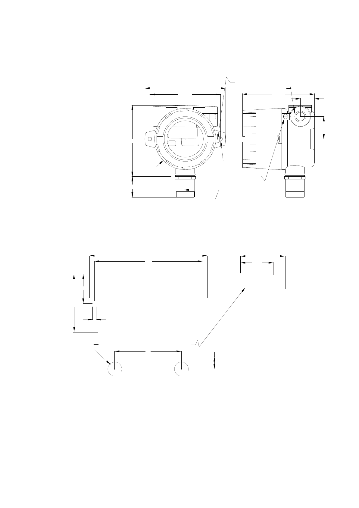
Mounting Details and Dimensions ATEX Versions
145.0
126.0
128.0
Ø110
EXTERNAL EARTH
40.0
COVER SECURING SCREW
M20 x 1.5
128.5
Ø7.0
MKIII FLAMMABLE
GAS DETECTOR
SHOWN
25.0
40.0
The ATEX version uses IGD’s JB3 series ATEX EXD terminal enclosure. Please note that cable glanding
and sealing must conform to ATEX requirements which is more fully described in the ATEX JB3 manual
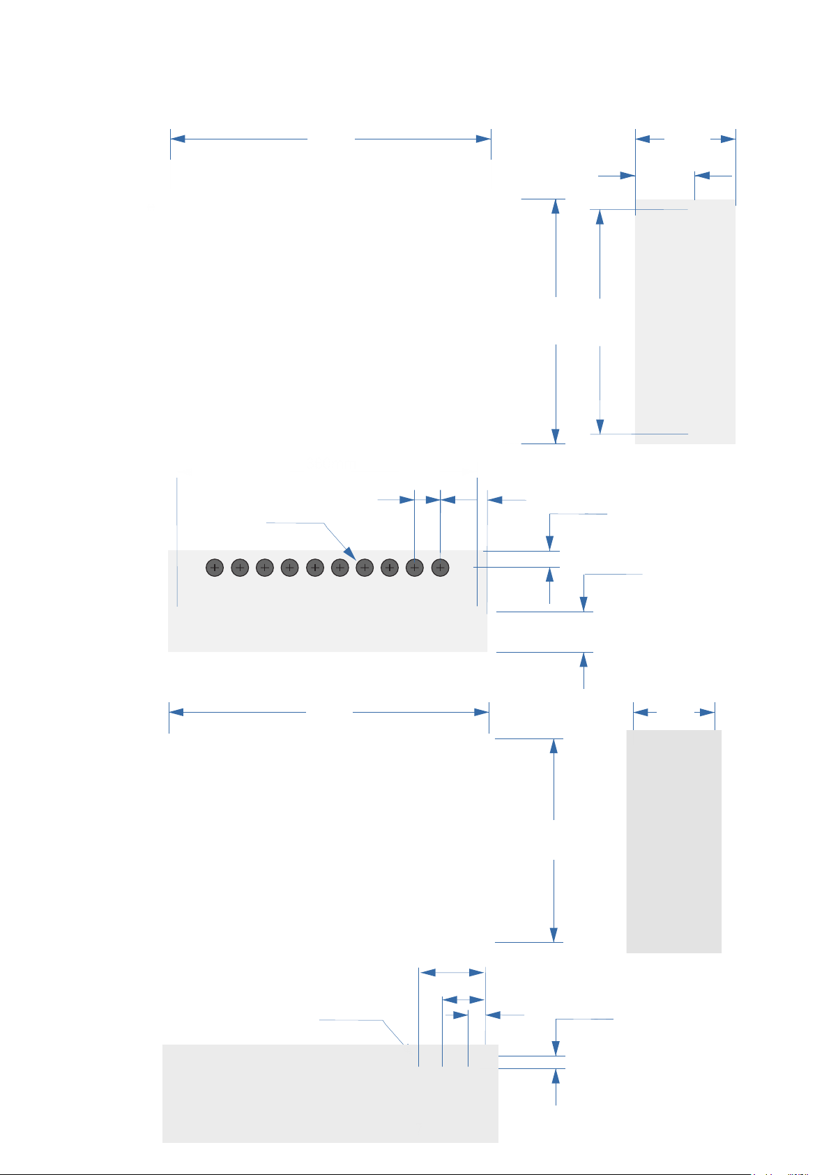
Mounting Details and Dimensions Safe Area Versions
172
158
76
48
43
86
5
20mm Entries Top, Bottom & Either Side
98
18
Note TOC-750-AN3 Shown
Detectors, Annunciators and
Nodes Share Common
Mounting Details
Gas Detector Types
Refer to individual data sheets for specific data relevant to available gas detectors, types,
accuracies and sensitivities available.
For pellistor type gas detectors complying to BS EN 60079-29-0 and 1, these general purpose
flammable gas detectors are suitable for Methane and LPG detection in the range 0-100% LEL.
Relative response to Methane @ 4.4% Vol = 100% LEL Equivalent to 55% LEL N-Butane
6
Page 8
Battery Backup Modules
TOC-750-BAT1 7AH Battery Backup with 150W PSU
382mm
120.5mm
72mm
Front Face
Bottom Face
10 off 20mm
Cable Entries
FRONT VIEW
360mm
30mm
56.5mm
292mm
20mm
Side Face
134mm
48.5mm
TOC-750-BAT2 17AH Battery Backup with 300W PSU
460mm
Front Face
4 off 20mm
Bottom Face
Cable Entries
95mm
60mm
25mm
115mm
Side Face
292mm
20mm
7
Page 9

SECTION 2
SITING GAS DETECTORS
8
Page 10

Siting Gas Detectors
Gas detectors usually fall into two groups for placement
1. Plant Protection. Typically flammable gas detectors fall into this category. Aside from asphyxiation
flammable gases are typically not directly toxic and so detectors are placed strategically where the gas is
expected to accumulate based on its relative density to air (lighter or heavier)
2. Life Safety Systems. Here the concern is that a toxic or asphyxiant gas is directly hazardous to
personnel and so the gas detection is placed based on the normal operating zone for the people present
Note that in many cases both life safety and plant protection sensors may be appropriate on a site. For
example a plant using liquid helium may have plant protection sensors at high level to ventilate roof
spaces in the event of leaks. However in the event of ventilation failure Helium could accumulate down
towards the zone where personnel operate. In this case a second set of life safety sensors would be
appropriate.
Each site should be surveyed and assessed on its own merits. This document presents general
guidance only.
Consider ceiling divisions, follow rules for smoke detectors
LPG
0-100%LEL
GAS DETECTOR
SN:20235-1-1 ADD:4110
Lighter than air gases, detectors placed at highest ceiling points
Consider fitting collector cones at lower level for gas bottle stores
boiler plant and gas meters (see separate application note).
Methane, Helium, Hydrogen, Ammonia etc
Life Safety Zone
CO, CO2, O2
H2S, NO2, NO
HCN, HCL, HF
NH3 etc
LPG
0-100%LEL
GAS DETECTOR
SN:20235-1-1 ADD:4110
LPG, CO2
Consider fitting splash/dust guards to protect low level sensors
1800mm
1000mm
400mm
Consider sensors in under floor areas/voids/drains where heavier than air gases are present
9
Page 11

5M
Air Gases Can
Show a Gradient
in Room Levels
With Higher
Concentrations at
Floor Level or
Heavier Than
5M is a Maximum Detection Distance and
Will be Effected by Topography.
Gas Levels Will Drop as Distance to Leak
Source Increases Requiring Lower Alarm
Set Points
Slow Leak Scenario
For this CO2 Example
use Detectors in
the Life Safety Zone
to Trigger Ventilation
and Evacuation Alarms
For this CO2 Example
Expect Higher
Concentrations at Low
Levels. Use for
Ventilation Trigger and
Pre-Alarms
High Concentrations Local to Release Source or Cloud Development Scenario
Siting Gas Detectors
CO2
100%
10
This Example Illustrating
A CO2 Gas Release From
A Storage Cylinder. Typical
Scenario, Broken or Blown
off Hose, Regulator Incorrectly
Connected, Ruptured Gauge
or Similar.
Page 12

Cryogenic Gas Detection
Applications involving Cryogenically cooled gases such as liquid Nitrogen or Helium need careful
consideration for gas detection. On initial release as cryogenically cooled gases can typically be at lower
temperature and high density than their surroundings they will behave differently than when in their
gaseous state. In such cases it should be considered if two sets of detection is required, one for the life
safety zone and one for low level detection in the gases cooled state. Applications involving such gases
are recommended to be surveyed.
Area Coverage for Gas Detectors
In a similar manner to smoke detectors, a gas detector can provide up to 75SQ M area coverage based on
a 5M radius of operation. There are many factors affecting this, geometry of a room, equipment in the area,
gas characteristics, ventilation air flows etc. IGD can support throughout the survey, design and installation
process to ensure the best possible result on site.
Max 5M Radius
Typically up to 75 SQ M Coverage
Calibration and service Requirements for Gas Detection Systems
All gas detection systems require regular checking and calibration to be in compliance with the UK
factories act. The service and calibration period will be a function of the application based on
environmental in service conditions. It is extremely important to ensure a service plan is in place for any
gas detection system installed as part of a site safety system. IGD can work with operators to provide
advice, service and spares to ensure an appropriate level of cover.
11
Page 13
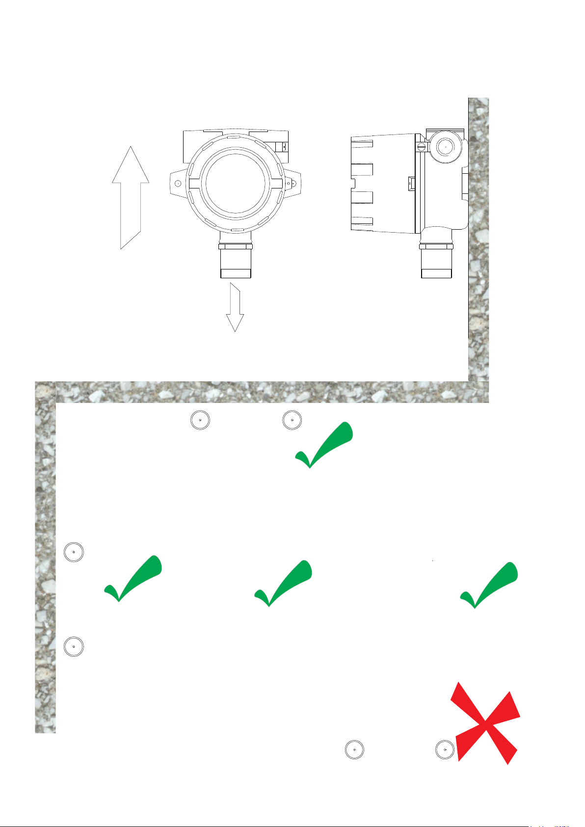
General Detector Mounting Positions Atex (BS EN 60079-29-1)
Detectors should be
mounted vertically with the
sensor face facing
downwards to protect from
contamination.
General Detector Mounting Positions Safe Area (BS EN 50194)
Sensor Facing Down
Sensor Mounted to Vertical Wall in Various Orientations
Do NOT Mount With The Sensor Facing Upwards
12
Page 14
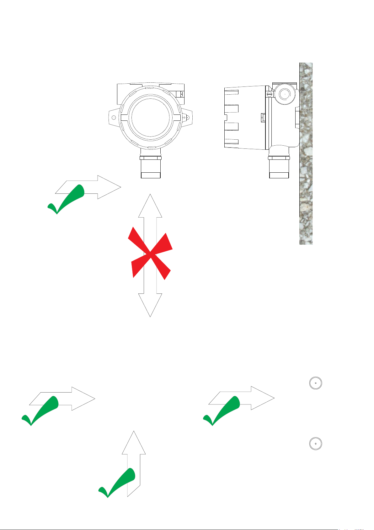
Detectors in Airflows Mounting Positions Atex (BS EN 60079-29-1)
Air Flows up to 6M/S Are
Allowable Without Any
Performance Issue Across
the front of The Sensor Face
Do NOT mount Detectors Where
Airflows Are Likely to be Directed
either onto or Away From the Sensor
Face. This Situation May Result in
Contamination and/or reduced
Detection Capability
Detectors in Airflows Mounting Positions Safe Area (BS EN 50194)
Air Flows up to 1M/S Are Allowable Without Any Performance Issue
13
Page 15

Siting System Components
Control Panels:
These should be located outside of the area protected by its connected
gas detectors.
The control panel should be accessible such that in the event of an
alarm the area can be evacuated and gas levels viewed from the
controller.
Consider the use of mimic panels, HMI panels or GSM options available
from IGD to provide additional remote indication/alarm
Audio-Visual alarms
As a general rule if there is gas detection fitted to an area then there
should be an audio-visual alarm (beacon sounder) to alert personnel
who may be in the same area. Typically these will be standard beacon
sounders where the sounder can be silenced from the control panel
once an alarm is accepted. Standard LED beacon sounder modules are
available from IGD and can be run from addressable I/O points to
minimise cabling. Another option is to fit IGD’s range of annunciators.
Annunciators
Annunciators are addressable devices typically fitted at door entry
points. They provide a clear audible visual alarm in the event of a gas
alarm to warn persons from entering an area where a gas hazard could
be present.
They offer many advantages over standard beacon sounders. They can
be fitted to standard dado trunking systems; cannot be confused with
other alarms; the displayed alarm message and flashing colour display is
unambiguous; they can be fitted with slam switches.
Gas Collector Cones and splash Guards
Where detectors are located above gas plant such as boilers or meters in
rooms with high ceilings then consider the use of gas collector cones.
These are fitted to detectors sited just above gas plant to enhance the
detectors capability to detect gas leaks (see separate application note)
For detectors fitted at low level, fitting splash guards may be appropriate
to protect sensors from dust, rain splash, floor washing etc.
14
Page 16

SECTION 3
GENERAL CABLING PRINCIPLES
CABLE TYPES
AND
CABLE SIZING
15
Page 17

Cable Type Guidance
IGD’s 2-Wire gas detection systems operate using screened cabling of appropriate cross sectional
area. There are no specific requirements and our typical advised cable types are indicated below.
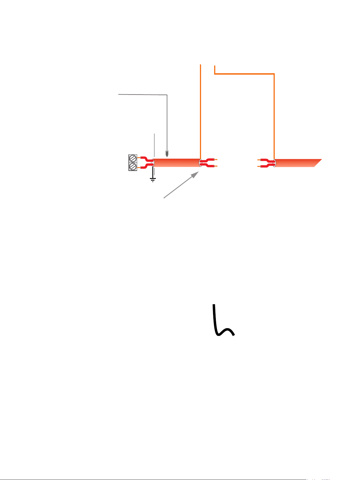
Cable screens, either foil and drain wire, braid or armouring must be continuous between devices and
grounded for effective operation. Ancillary devices such as stop buttons, beacons, sounders etc should
commoned to the earth blocks provided as indicated below.
Recommended Cable Preparation
CY Style Cable
CY Type cable has a braided screen which should be trimmed
back to ensure no trimmed conductor ends up on sensitive
PCB components, tracks or terminals where it may short. The
screens of the incoming cables should be terminated to the
floating terminal block provided to ensure screen continuity.
Trim back any unused conductors and ensure the braid is
insulated with heat shrink or insulation tape and/or sleeve.
Unused
L1
L2
Cable Screens direct to
commoning blocks provided
L1
L2
Strip Conductors 7mm Ensure No Stray
Strands
FP Style Cable (Preferred Option)
FP style cable is fitted with a foil screen and drain wire. Generally this is easier to terminate than
CY type cable. Trim back any unused cores and foil screen. Ensure the drain wire is insulated
with suitable size sleeving and terminates to the cable screen terminal
L1
Drain Wire Screen
L2
SWA Style Cable
SWA style cables are usually only recommended for used with ATEX EXD housings where the
universal cable glands ground the cable armour to the housing. This provides both an effective
EMC screen and mechanical protection. Ensure unused conductors are trimmed back and
isolated. If terminating to plastic enclosures fit ‘pan handles’ and terminate on the outside of the
enclosure to ensure screen continuity
L1
L2
Unused
16
Page 18

Main Base PCB Connectors
When unplugging detectors from the main PCB DO NOT lever them off. This will potentially cause
damage to the PCB and/or connector mating parts and invalidate any warranty. If it is necessary
to remove the PCB connectors use long nose pliers.
17
Note that connectors can be plugged either
vertically or Horizontally to the PCB
Page 19

Cabling: When using stranded cable fit bootlace ferrules to
prevent stray wire strands shorting.
Cable glands must be used for cable entries.
System Example
LPG
0-100%LEL
GAS DETECTOR
SN:20235-1-1 ADD:4110
2-Wire
Addressable
Controller in Supervisors Office
Where Required For Longer Cable Runs
or Where Device and Accessory Density
is High add Power Boosters or Cascade
Hubs to Increase Distance Capability to
up to 3KM
Use Annunciators For Door
Entry Control.
Use Annunciators with Gas
Detector Interfaces to Detect
& Alarm in Specific Areas
Laboratory
LPG
0-100%LEL
GAS DETECTOR
SN:20235-1-1 ADD:4110
Mix Annunciators With Other
Addressable Devices Such as
TOC-750 Series Detectors.
Use ATEX Rated detectors
where required
ATEX Zoned Area
2 Core Highway as:
24V L1,L2
Typically 1.5mmSQ
Unscreened Cable
18
Gas Bottle Store
Use the Detector or
Annunciator I/O
Capability to Control
Gas Supply Valves,
Beacon-Sounders or
other devices
Page 20

Interfacing to the Remote Modbus Port
The Tocsin 750 series controllers have an in-built memory map allowing access to alarm status, panel
status, readings etc using Modbus RTU protocol. Wiring between units is as follows:
RS485 Modbus
ScreenBA
Comms Port
0V DC
Master DCS/BMS
Note only the A,B and 0V DC Connections are
Used. 0V DC between master and slave should
be connected for correct operation and to prevent
damage to both master and slave systems
Fit terminating
resistor at last
device across
A-B 120 Ohms
RS485 Modbus
BA0V DC
Comms Port
BA0V DC
RS485 Modbus
Modbus
Address
100
Tocsin 650/750 Controller (slave) Tocsin 650/750 Controller (slave)
More than one controller can be interfaced on the same Modbus cable by
assigning individual Modbus addresses to each controller.
Refer to users guide for Modbus channel mapping
Cable Sizing
Up to 400m use minimum 1.0mm cable with an overall cable screen.
Cable runs over 400m use 1.5mm cable with an overall screen
2
2
Comms Port
Modbus
Address
99
19
Page 21
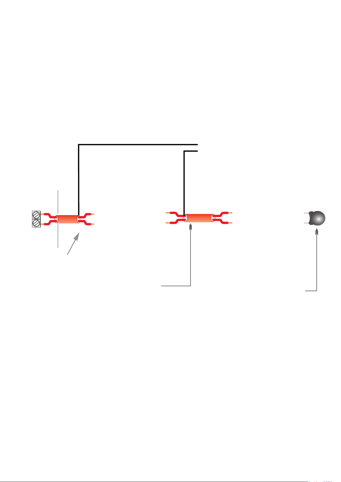
Interconnecting Modules On A Data Highway
Tocsin 750 Series Annunciator Modules are interconnected as follows using two core cable.
The system is designed to operate using screened cable. In some circumstances, for instance
in ATEX Zone 1 areas a protective armour may be desirable to provide mechanical protection.
The system provides both power and digital communication over the single pair of wires. The
system is also polarity insensitive although best practice would be to connect L1 to L1 to L1
and L2 to L2 to L2 etc for continuity. It is necessary to fit an IGD terminator at the last device
as indicated for operation of the system. In-coming and out-going screens must be connected
as indicated, ensuring screening continuity. IGD provide screw-less terminal blocks for this
purpose. Ancillary cabling to push buttons, beacons, sounders etc should also be screened.
TOCSIN
650 OR
750 Series
Controller
L1
L2
Port 1 to 4
Cable Screen or
Drain Wire
Cable Screen or Drain Wire
Interconnecting Highway Cabling
For 2-Wire Addressable Systems:
For Safe Area Detectors Use 2 Core
Cable 1.0 to 2.5mmSQ Cable
Depending on Distance.
Ensure Cable Screens are Correctly
Terminated and cables are stripped
to the enclosed guide.
For ATEX Units Typically Use 2 Core
SWA Cable 1.0 to 2.5mmSQ
Depending on Distance
Screen continuity terminal block
End of Line Terminators Must
be Fitted at the Last Module in
Line as Indicated Across the
L1 and L2 Terminals.
Terminators are Shipped With
All Control Panels.
Spare Terminators Can be
Ordered Using Part Number :
TOC-750-TRM.
Failure to Fit Terminators Will
Prevent System Operation
See Cable Calculator for Cable Core
Size vs Distance VS Number of
Devices
20
Page 22
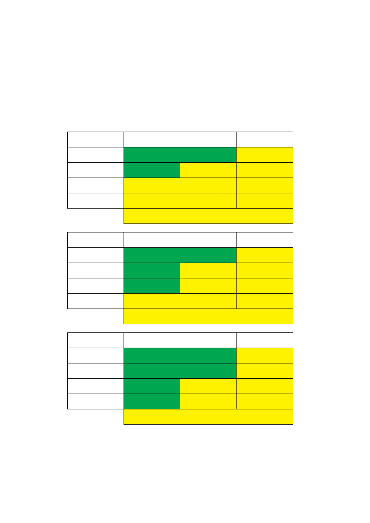
Cable Sizing
The total number of devices that can be supported on a cable highway will be limited by the
reset fuse on the PCB, the cable length and size fitted and the power requirement for each
module. The controller reset fuse is set to 2A. The following table is intended as a guide to show
the number of devices that can be run taking into account the volt drop for differing cable sizes
before boosters need to be employed.
1.0mm Cable / 17AWG
1.5mm Cable / 15AWG
2
Length (M)
250
500
750
1000
2
Length (M)
250
500
750
Toxic
32
32
26
20
Booster Module Required For Increased Detector Nodes
Beyond Indicated Numbers
Toxic
32
32
32
Pellistor MK6/7*
32
21
14
10
Pellistor MK6/7*
32
30
21
Pellistor MK3**
23
14
9
7
Pellistor MK3**
25
20
14
1000
2.5mm Cable / 13AWG
2
Length (M)
250
500
750
1000
30
Booster Module Required For Increased Detector Nodes
Beyond Indicated Numbers
Toxic
32
32
32
32
Booster Module Required For Increased Detector Nodes
Beyond Indicated Numbers
Pellistor MK6/7*
16
32
32
31
26
11
Pellistor MK3**
28
24
21
18
* – Also Ann & Toxic & Relay – Also Ann & Toxic & Display – Also Ann & Beacon/Sounder
** – Also Ann & MK6/7 & Relay – Also Ann & MK6/7 & Display
NOTES:1: Assumes PSU voltage is 26.5V2: Assumes all Annunciators are spaced evenly on cable3:
Assumes on other outputs or inputs are disabled on Annuciator4: Assumes voltage drop acrros Ann
L1 to L1 is less than 25mV5: Assumes voltage drop acrros Ann L2 to L2 is less than 25mV6: Ann with
T102A=0.6W, Ann with MK6/7=1.1W, Ann with MK3=1.6W
21
Page 23

SECTION 4
MAKING DEVICE CONNECTIONS
TO DETECTOR NODES
22
Page 24
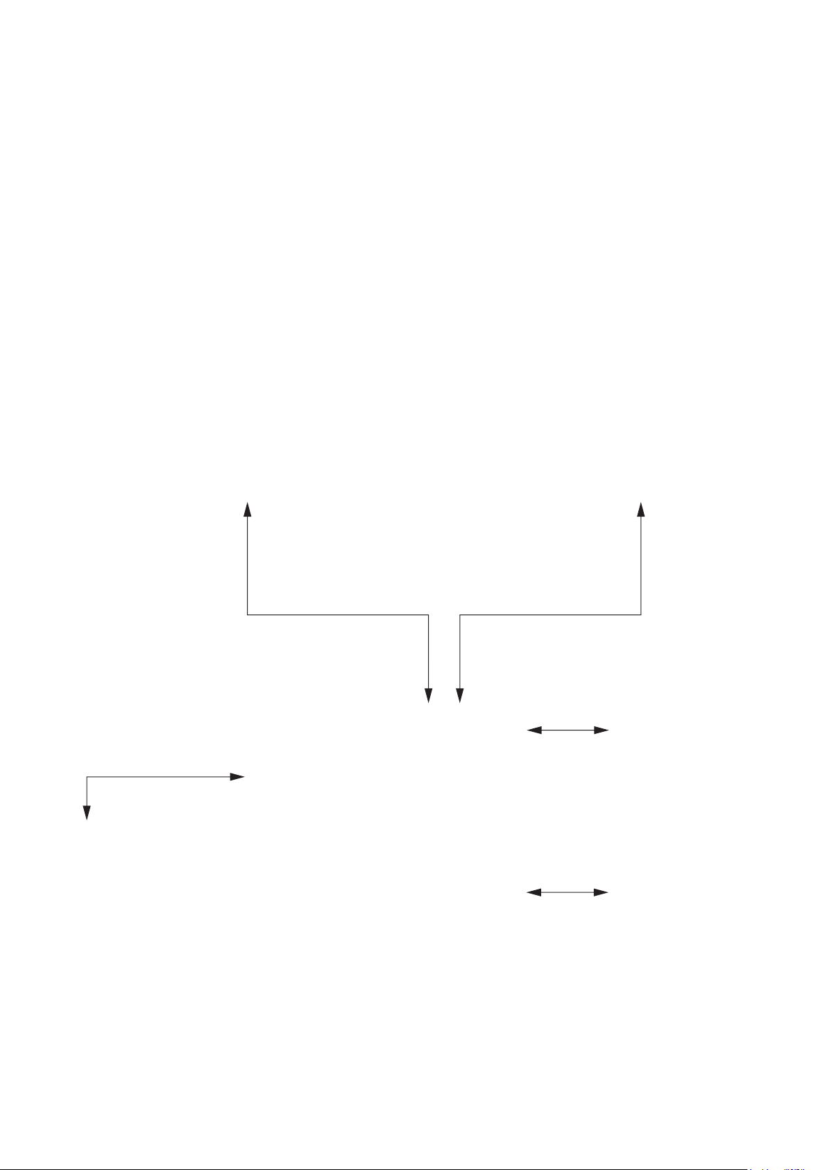
Mains Power and Controller Overview
Display Option 1 (750)
7” Colour Touch Screen HMI
PSU Options:
70W
150W
300W
All Closed Frame
Stock Switched
Mode PSU With
their Own
Important
Approvals
In all cases mains connection must be made via a 2-Pole Isolating supply
Display Option 2 (650/635)
2 x 8 RGB LCD and Jog
Wheel
Hub Card PCB Common
to All Assemblies.
Note entry level 635 version
is a part populated PCB
supporting fewer detectors.
2 off 5AH Lucas Gell
Lead Acid Batteries.
Fitted as an option
where battery backup
required
Where stranded cable is used for mains power termination, fit bootlace
ferrules to ensure there is no possibility of stray wire strands
23
Page 25

Mains Power and Controller Overview
Controllers with mains power supplies must be fed via
a unique fused spur fused at 3A.
Use ferrules or 4mm fork crimps to prevent stray wire
strands and potential shorting
Note incoming Earth connection
Incoming Panel Earth
L N
Earth Point for
Cable Screens
For Detector Nodes,
Comm’s Connections
Power supplies are switched mode types.
Note dependent on PSU type the incoming voltage may require to be set using a switch setting
between 110V AC and 230V AC. If this is the case note the current switch setting indicated on the
PSU label before connecting power. If the setting requires changing to suit the incoming voltage
then make this change before connecting power and re-label accordingly.
Failure to ensure the PSU is correctly set to match the incoming voltage will result in
permanent damage.
CONTROLLERS MUST BE CORRECTLY EARTHED TO ENSURE CORRECT OPERATION
24
Page 26

Connection Possabilities
The 750 Series Module PCB Operates as an Interface ‘Hub’ on the Addressable 2-Wire Highway.
The Diagram Below Shows a Typical Set of Connection Possabilities
8/9
1
2
4/7
I/O Port 2
Either Input
or Output
5
Device Address Table
Option
1
2
3
4
5
6
7
8
9
Type
Input
Input
Input
Input
Output
Output
Output
Input
Input
Device
Gas DetectorPellistor
Toxic Gas Detector
TOC-10
4-20mA
Relay & OP1
Solid State Output
Solid State Output
E-Stop
Key Switch
3/6
Device Address
1
2
3
4
102
103
104
5
6
I/O Port 1
Either Input
or Output
Note that one 2-Wire addressable highway running Sentinel+ protocol can support up to 32 modules.
Each module can have up to 8 connected devices. IGD Configuration software is used to configure the
module PCB to switch devices on and off and set addresses (see Tocsin 650/750 Manual). If the
connected devices have already been configured then the base address can be set from which all other
module addresses will sequentially follow. This is described later in this manual. Device addresses
indicated in the table are typical but can be individually set.
25
Page 27

Module PCB Features
The following diagram indicates features available on the TOC-750 ‘module’ PCB. Please note
that failure to observe and make correct connections or exceed ratings may result in damage to
the PCB.
Pellistor (Catalytic)
Flammable Gas
Detector Interface
Suitable for IGD
Types MK3, MK6, MK7
Connection Point For
IGD Infra-Red, Toxic, PID
or Oxygen Gas Detectors
Multi-Function I/O Port 2
Solid State Output or
4-20mA Input or
TOC-10 IP or Gas Meter
2-Wire Highway
Connection
To Next Device
DVM Test Point +
SPCO Relay
Output
6
5
4
P
Y
W
Ribbon Cable Connection For TOC-750
Annunciator Display and Options
7
3 3
1
2
Multi-Function I/O Port 1
Solid State Output or
4-20mA Input or
TOC-10 IP or Gas Meter
1
2-Wire Highway
Connection
To Next Device
DVM Test Point -
Module PCB Basic Interface Specifications
Housing
Sealing
Environment
Temperature
Voltage
Communication
1
Relay
2
Digital Output
3
Digital Input
Pellistor Port
4
Sounder
5
Display
6
Comm Port
7
TOC-750 Series ABS or Copper Free Aluminium For ATEX Versions
IP65 (using suitable glanding) for TOC-750, IP68 for ATEX Versions
0 -95% RH Non Condensing
0-55 Deg C
12-28V DC
IGD 2-Wire Highway Operating IGD Sentinel+ Protocol
Not Polarity Dependant
5A Non Inductive Loads 230V AC
24V DC 100mA Combined For Both Outputs Typically for LED Beacon Sounders
Suitable for use with TOC-10 Link Function
Option to Interface to MK3, MK6 or MK7 Pellistors
85dB (Option for TOC-750 Annunciators)
2 x 8 Programmable LCD with RGB Backlight (Option for TOC-750 Annunciators)
Supports IGD Infra-Red, PID, Toxic and Oxygen Gas Detectors
Local LED
Indications
And Up/Down
Interface Buttons
26
I/O Connection Port Selection Options
4-20mA Input 24V Powered From PCB
4-20mA Input 0V Powered Externally
Voltage Input 0V 0-3V DC Analogue
Digital Input 24V as contact closure
Digital Input 0V External Logic Input
SSR Output (SW+) Switched + DC 24V Output
SSR Output (SW-) Switched - DC 24V Output
SSR Dual For Beacon Sounder Operation
Page 28

Gas Detector Connection
The most commonly supplied detector node comes pre-fitted with a gas detector. The
detector front assembly simply plugs onto the indicated connector. Note that all detector front
assemblies have a common system address. The detector node module is designed to read
the data from this address and report it back to the control panel using its own ‘unique’
address.
This makes service replacement very simple as the detector assembly is pre-calibrated and
can just be plugged in to enable operation.
If detector modules are changed to add or change the detected gas type then the controller
will need to be amended so the channel reads and scales correctly and so that alarm levels
are appropriate.
27
Page 29
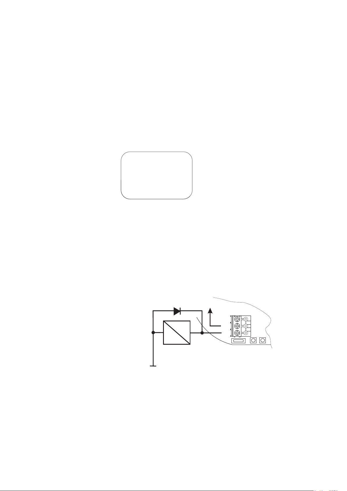
Relay Output
The Detector Node relay output can be used as an alarm interface to external systems, run
additional audio visual alarms or directly control other devices. Typical applications could be gas
solenoid valves, boiler shut down interfaces or similar. When switching external loads it is important
to consider the nature of the load being switched. For inductive loads suitable protection from
induced back EMF must be fitted. Many modern devices conforming to the European EMC
Directive may already have devices fitted as part of their design to limit in-rush currents and back
EMF. Where these are not fitted the following two diagrams provide guidance. Failure to observe
this may result in damage to the Detector Node.
Example fit protection
diodes when switching
external DC loads.
1N4004 Diodes.
For Diode Packs
IGD PN: TOC-750-DIO
A2
0V DC
28
24V DC
A1
NC
COMM
NO
FOR DC LOADS
DO NOT EXCEED
30V DC 5A
Page 30

Solid State Output
Each Detector Node has 2 multi-function input - output ports. These can be configured
independently as either 4-20mA inputs, Digital Inputs or solid state outputs. The solid state outputs
are typically intended to switch small loads such as LED beacon sounder modules or small signal
interface relays as indicated below. As standard Detector Nodes Ship with I/O Port 1 and 2 setup
as Solid state outputs, negative switching
I/O Port 2
I/O Port 2
I/O Port 1
Wiring to I/O Port 1 and 2
The Solid State Outputs Can be used to
Switch LED Beacon Sounders if Required.
It is recommended to use IGD LED
Beacon Sounders Part Number 5083101
Connections Shown are for 5083101
and shown one output switching the
beacon and one port switching the
sounder. This allows the controller to mute
the sounder on accepting an alarm.
When using Other Manufacturers Devices
do Not Exceed 100mA @ 24V DC Total
combined Load for Port 1 and Port 2
Use screened cabling
When Switching Small interface relays
ensure protection diodes are fitted as
indicated, these are supplied with the
module. Failure to do so can result in
damage to the output. Ensure relay coil is
rated at 24V DC and Max 100mA or Min
240 Ohms.
Do not exceed 100mA Load Port 1 and
Port 2
Beacon
Sounder
1 2 3 4
IN+
OUT+
V+
4-20mA
Screen cabling interfaced to I-O port 1 or 2.Typical
Belden Style Security Cable 4502 FE, Foil Screen
Protection Diode 1N4004
V+
4-20mA
A1 A2
Typical 24V DC Relay
15mA 1600 Ohm Coil
29
Page 31
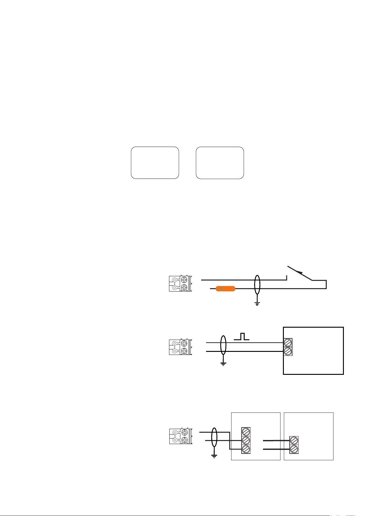
Digital Input
Each Detector Node has 2 multi-finction input - output ports. These can be configured
independently as either 4-20mA inputs or solid state outputs. The digital inputs are typically
intended to totalise pulse counts, mainly from gas meters, or use for slam switch/ E-Stop
applications
I/O Port 2
Wiring to I/O Port 1 and 2
Wiring to I/O Port 1 and 2
I/O Port 1
If You Are Wiring Digital Inputs (24V)
Option Then You Need to Include a 560
Ohm Resistor to Limit Current Around the
V+
4-20mA
Circuit
Screen cabling interfaced to I-O port 1 or 2.Typical Belden Style Security Cable 4502 FE, Foil Screen
If You Are Wiring Digital Inputs (0V) Option
Allows Logic inputs from External Devices.
Anything Less Than 1.5V DC is Treated as
V+
4-20mA
External System
0V
I/O Digital
Off Anything Greater is On
Solid State Input From TOC-10 Gas Detector
The Solid State Input can be used to
interface to IGD TOC-10 Series
Flammable Gas Detectors. Wire as
Indicated and the Input Will Read the
Two Alarm Levels From the TOC-10.
This will display on an Addressable
Controller in the Same Manner as Any
Other Gas Detector.
Up to 6 TOC-10 Detectors can be Daisy
Chained to the Input
30
V+
4-20mA
TOC-10 Unit 1 TOC-10 Unit 2
Spare
I/O
0V
Spare
I/O
0V
Page 32

Digital Input.... Gas Meters
To be able to read a digital pulse train from a gas meter volt free contact or similar it is necessary to
use adaptor cable part number TOC-750-GMA. The following diagram indicates fitting the cable
and field wiring to a volt free contact.
Accessory Port
I/O Port 2
I/O Port 1
Gas Meter Adaptor Harness
PN TOC-750-GMA
The Solid State Input Will Accept up to a 0.2
Hz Pulse Train Input From a Gas Meter or
Similar Device With a Volt Free Contact.
The Following Scaling Options Are Available:
1 Pulse = 0.1M
1 Pulse = 0.01M
1 Pulse = 0.001M
3
3
3
Field Wiring
Ensure
Screening
Gas Meter Reed Switch
31
Page 33
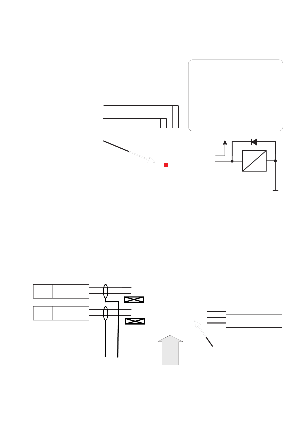
4-20 mA Inputs
Each Detector Node has 2 multi-finction input - output ports. These can be configured
independently as either 4-20mA inputs or solid state outputs. When used as 4-20mA inputs any
standard 4-20mA loop powered can be read in as an analogue signal. Using the setup routine the
signal can be scaled and then read back addressably onto the system controller.
I/O Port 2
Wiring to I/O Port 1 and 2
a) For a 2 Wire Loop Powered Device (4-20MA 24V Option)
The Input Sources a 24V DC supply then
sinks the signal current on the module PCB
V+
4-20mA
across a 122 Ohm resistor on the PCB
I/O Port 1
Loop Powered 2 Wire Sensor
24V DC
4-20mA Signal
b) For a 2 Wire 4-20mA Device Externally Powered Device (4-20MA 0V Option)
24V DC Power is supplied
External Power
from an external source then
sinks the signal current on
the module PCB across a
100 Ohm resistor on the
PCB. Note if the externally
powered sensor does not
have an isolated output then
a separate isolator must be
V+
4-20mA
Isolator
+ +
- -
Externally Powered 4-20mA
Sensor
0V DC
24V DC
4-20mA Signal
fitted as indicated. These
may or may not require
external power. The IGD
Option shown is loop
powered PN TOC-MA-ISO
32
Page 34

Pellistor (Catalytic) Flammable Gas Detector Interface
The Detector Node PCB is equipped with a Pellistor or Catalytic flammable gas detector
interface. This supports all IGD manufactured pellistors as indicated below. Note that the
correct pellistor option must be selected in the setup software routine for the pellistor to operate
correctly.
The Pellistor can be mounted remotely from the PCB. When doing so do not exceed the
indicated cable length.
For remote mounting use 1.5mmSQ Cable. Do not exceed 10M
This cable to the pellistor may need
to be screened in electrically noisy
environments.
This will not normally be required if
other items of heavy electrical
equipment are not present
V DC
P
Y
W
IGD Pellistors Supported
Type Head Head
Current Volts
2.20
Com
Volts
MK3 ATEX EXD IIC T6 360mA 2.2V
MK6 Safe Area 170mA 2.5V
MK7 Safe Area 170mA 2.5V
Note: The Pellistor ‘Type’ is selected using IGD service tool app or by using the setup routine in the
TOC-750 Software. Once selected this automatically sets the head supply voltage.
In operation and with zero air applied correctly to the detector the ‘balance’ between the two detector
‘beads’ as measured P-Y and Y-W should not show a difference of more than 70mV. If the difference
is larger than this then it could be an indication of aging or damage and the detector should be
replaced.
33
Page 35

SECTION 4
Control Panel Interfaces and Connections
34
Page 36
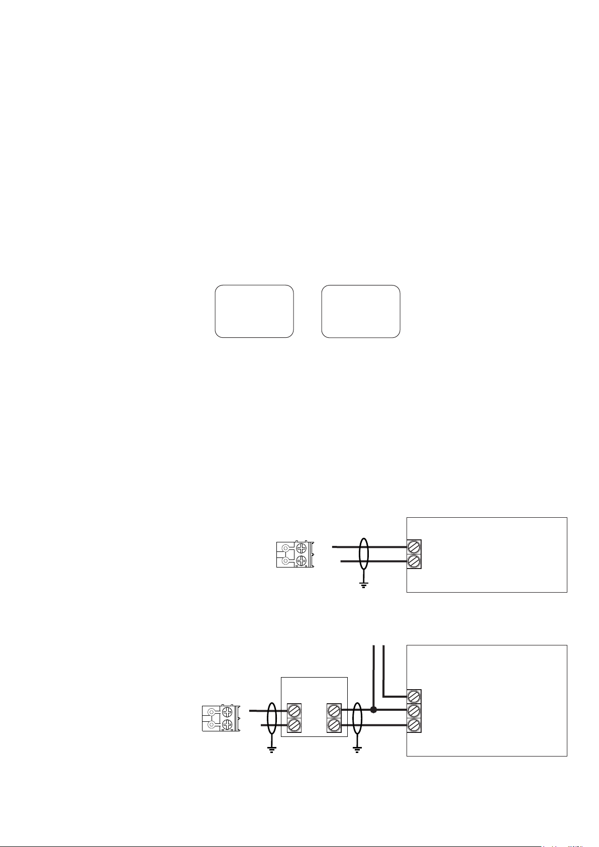
Tocsin 650 and 750 Control Panel & New 2 Wire Hub PCB Features
Battery Connection
For Battery Backup
Power in
24V DC
L1
*
Ethernet
Bluetooth
L2
L1
Rs485 Remote
(Modbus etc)
*
USB
L2
L1
L2
Display
Colour HMI
Display TOC-650 (2x8 LCD)
L1
Fault Relay
Alarm Relay 1
Alarm Relay 2
Alarm Relay 3
Inputs for E-stops/Fire
L2
Direct Beacon-Sounder O/P
4 off 2 Wire Ports Each supporting 32 Devices
128 Devices in Total
*
Cable
Highway 4
Notes
Hub cards can be cascaded to add more ports if required
Two display options, either 650 style with jog wheel
or
HMI Style touch screen display
Note both displays can be fitted at the same time which can allow the HMI display to be remote
from the panel and used as a system repeater or mimic.
Maximum of 32 Devices on a highway.
Maximum of 99 Sensor address on a highway.
Maximum of 99 Relay address on a highway.
*
Cable
Highway 3
Cable
Highway 2
Cable
Highway 1
*
Options Not Available on 635 Version
Maximum of 2A per Highway Without Additional Power Booster Modules.
35
Page 37

Panel Inputs 1 and 2 Cable 0
The 750 hub card is fitted with two digital inputs for use when interfacing to volt free contacts.
These can be used for example with slam switches or a relay output from another system
such as a fire alarm panel. They appear during a FIND command on cable 0 (internal to the
hub card) and will have input addresses 1 and 2 assigned by default. Alarms can be set
against these two channels in the same manner as any other detector. Note these channels
are supplied linked out and will always be the first two channels on the control panel.
switched inputs 1 and 2, volt free contacts
Normally Closed Loops Opening on Alarm
Note these inputs typically used for call
points / input from Fire Systems etc
Slam Switches
Address = 1
Alarm and Fault Relays
Fault
101
The four relays included on the hub
card can be assigned to alarm levels
in the relay alarm routine. They
appear on internal cable 0 during a
relay FIND.
Key Switches
Address = 2
All Relay
NO COM NC
Relay
102
Relay
103
Relay
104
24V DC
FOR DC LOADS
COMM
Normally Open
A2
DO NOT EXCEED
30V DC 5A
A1
0V DC
Example fit protection diodes when switching
external DC loads. 1N4004 Diodes are provided
with each module.
For Additional Diode Packs
IGD PN: TOC-750-DIO
All 4 relays are normally energised,
de-energising on alarm or on loss of
power to panel
36
Page 38

Panel Beacon Sounder Output
The 750 hub card is fitted with two SSR outputs intended for use with Beacon Sounders.
During a FIND command these will appear on cable 0 (internal to the hub card) and can be
assigned to alarm levels during the alarm setup routine. Addresses will be assigned as 105
and 106 during the FIND operation.
The 750 Hub Card also
incorporates a built in
sounder. This also has its
own address and will appear
by default as relay O/P 107
after a FIND operation.
Output Drive 24V DC
@ 100mA
1 2 3 4
IN+
OUT+
Beacon
Sounder
Sounder is Address 105
Beacon is Address 106
Panel Displays
Two display option are available. A 2 x 8 RGB LCD, supplied as standard on the 650 model and a
colour HMI touchscreen supplied as standard on the 750 model. Both run from different ports on
the same hub card.
TOC-750 Style display connects through an
RS485 Interface which allows the display to be
remote from the hub if required
TOC-650 Style display connects
using a ribbon cable interface
and must be local to the hub PCB
37
Note the hub PCB can run either
display, both together with the
HMI display remote or the hub
can run ‘blind’ with no connected
display.
Page 39
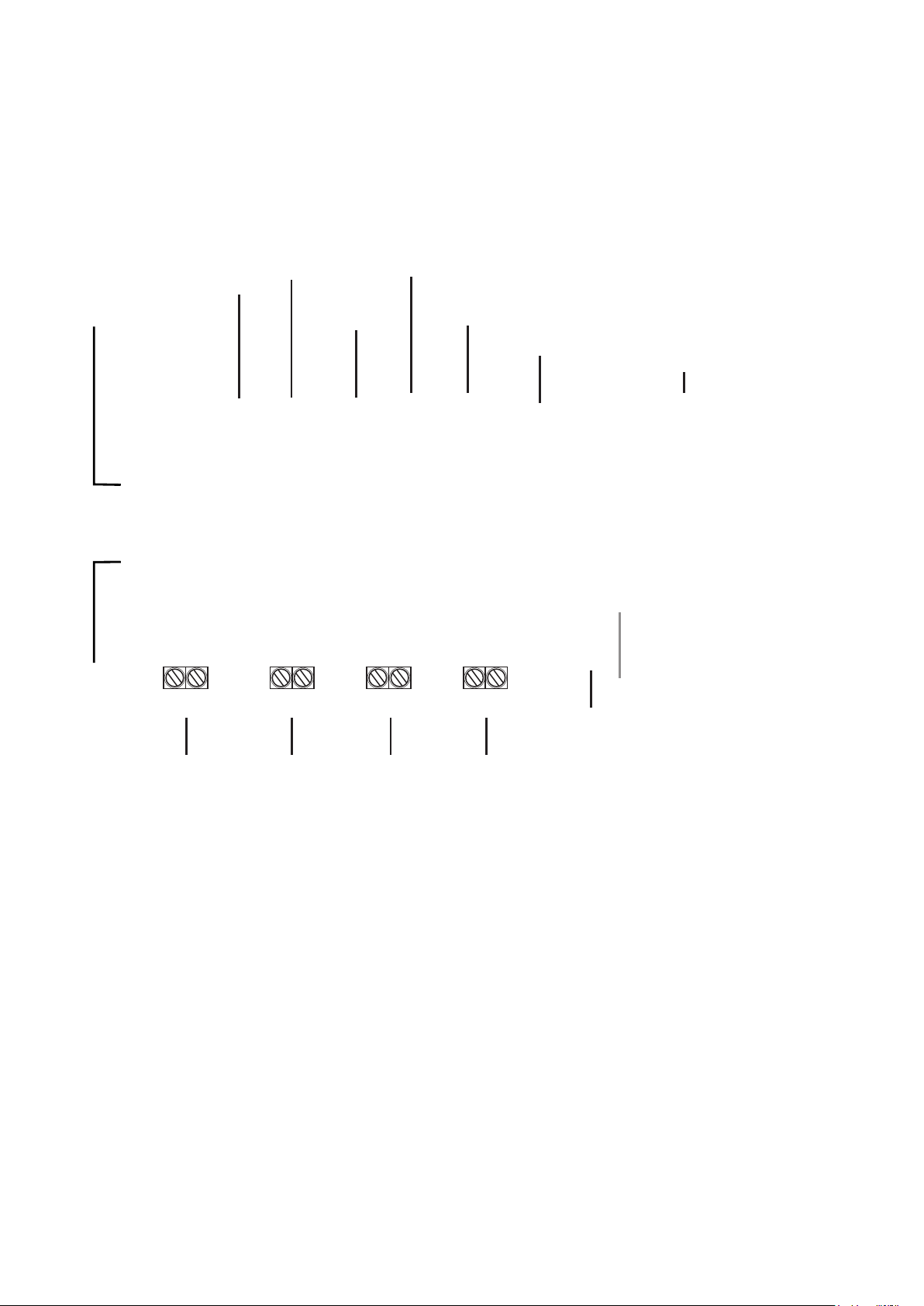
Tocsin 650/750 Addressable Relay Card
Power out for
use in
conjunction
with relays
0V DC
24V DC
In all Cases:
Relay contact ratings.
5A @ 250V AC Non-Inductive
5A @ 30V DC Non-Inductive
Spike suppression must be fitted
Note that FAULT relays are normally
energised on power up.
Relay status LED,
ON when Energised
10 off Digital/Analoge Input Ports
2-Wire Highway Connections
24V DC
A1
Example fit
protection
diodes when
switching
external DC
loads.
A2
0V DC
Pin 1 Line 1
Pin 2 Line 2
Pin 1 Line 1
Pin 2 Line 2
Cable Screens Must Be
Connected and be Continuous
Base Address set up
LED's and interface
for the relay card
38
Normally Closed
Common
Normally Open
Relay Terminals
First Relay on
The Card (relays
number from
this one).
Page 40
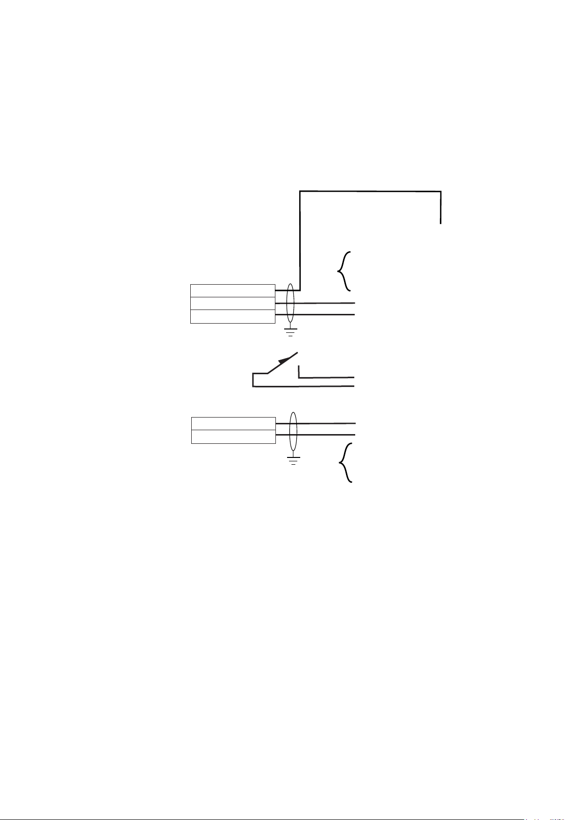
Tocsin 650/750 Addressable Relay Card Input Ports
Relay cards also have analogue and digital inputs that can be used to read data onto the system
from external devices. Setup of the inputs, type, range, addressing etc is controlled via IGD’s
Android Apps. Wiring options are indicated below. Note the differences between Version 1 and 2
PCB assemblies.
Typical IGD Loop Powered
4-20mA Detectors
Pellistors Based Detectors
Infra Red Based Detectors
PID Based Detectors
Thermal Conductivity
Typical IGD Loop Powered
4-20mA Detectors
Temperature
Pressure
CO
H2S
Oxygen
HCN
HCL
NO
NO2
H2
CL
SiH4
O3
3 Wire Detectors
0V DC
4-20mA Signal
24V DC
Loop Powered Detectors
4-20mA Signal
24V DC
Note 1
Note 2
10
9
8
7
6
5
4
3
2
1
Note 1
Note 2 These Ports are not used on version 1 PCB assemblies limiting the PCB to a maximum of 6
These Ports are designated to be digital inputs only.
analogue inputs or 8 digital inputs including ports 9 and 10
39
Page 41
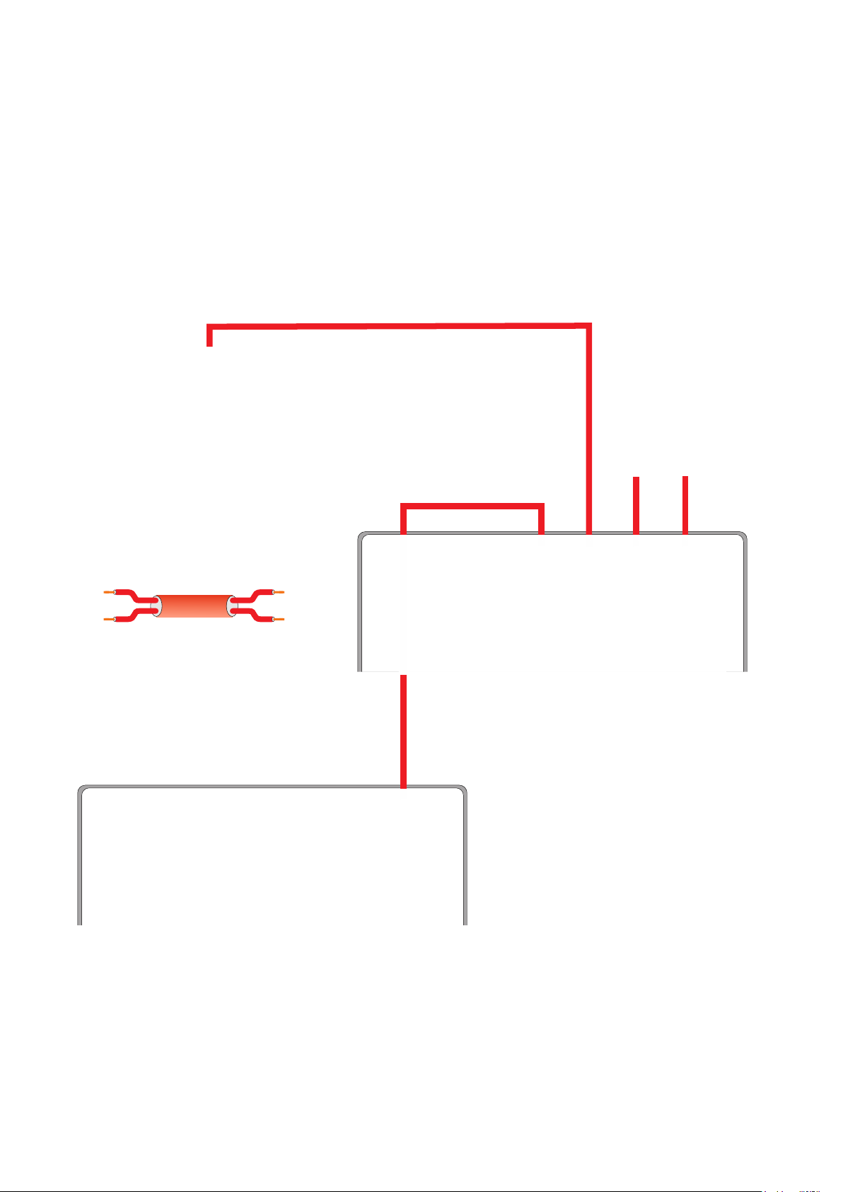
Cascading Controllers and/or Hubs
Hub cards can be cascaded together. This can be to allow master and slave panels to network
systems together or to gain extra distance on a cable network or add more cable highways. The
two wire system can be cascaded down two levels. With its capability to transmit up to 1000M,
cascading down 2 levels means systems can be up to 3KM long.
Note that on the top level master panel only cable 1 and cable 2 support cascading.
Hubs cards can operate without displays
and can be DIN rail mounted into
enclosure systems such as IGD’s range of
field boxes
IMPORTANT NOTE
Cabling between panels/hubs can
be up to 1000M
Ports not used for
cascading links each
support 32 detector nodes
or relay cards
The Cascaded links between
panels are polarity sensitive as:
+L1
-L2
Failure to observe this will result
in damage to the hub card
Ensure Cable Screens Are
Earthed to PSU Earth.
+L1
-L2
40
In this example the main master panel at
the start of the cascade will see all the
detector nodes and relay cards installed
on panels below it.
Page 42

External Battery Backup and Power Booster Modules
Both the 650 and 750 series 2-Wire control panels can accommodate 5AH internal batteries for
battery backup. If battery backup is required for longer time periods than the internal batteries
allow then external battery backup units can be employed.
Two external battery back options are available. 7AH and 17AH as follows:
650 or 750 Series Controller
Cabling between the
battery backup module and
control panel should be 4
core 1.5mmSQ cable.
Keep the distance between
battery backup module and
controller to less than 2M.
TOC-750-BAT1 7AH Option
150W PSU
OR
TOC-750-BAT2 17AH Option
300W PSU
Note that the main control panel needs to be a 24V DC version as
the external battery backup units house a mains power supply. The
battery backup modules should be fed from a mains fused spur.
41
Page 43

Device Loadings for Battery Backup Run Time Calculation
Indicated power is with the device in full alarm with all its I/O points energised.
Device
TOC 750 Controller
TOC 650 Controller
External Hub Card
Relay Card (All 8 Relays Energised)
I/O Node
IR/Pellistor/PID Detector Node
IR/Pellistor/PID Detector Node with MK6/7 Pellistor, Relay On
Toxic Gas/ Oxygen Detector Node
Toxic Gas/ Oxygen Detector Node with MK7 Pellistor
Node with 2 x 8 RGB Display
Node With MK6/7 Pellistor & 2 x 8 RGB Display
Max Power in Watts
13
7.9
7
8.5
1
1.24
1.64
1.1
1.73
1.89
2.52
IGD Beacon Sounder (PN 5083101)
Cable Dissipation 1000M 1.0mmSQ (Approximation)
Cable Dissipation 1000M 1.5mmSQ (Approximation)
Cable Dissipation 1000M 2.5mmSQ (Approximation)
Example
Item 1: Tocsin 650 Controller internal 5AH Battery
Item 2: 4 off Toxic Gas Detector Nodes for Ammonia
Item 3: 2 off Oxygen Gas Detector Nodes
Item 4: 2 off IR Gas Detector Nodes for CO2
Item 5: 3 off Beacon Sounders
Calculation
Available Battery Power = 5AH x 24V = 120 Watt Hours
Total Device Power =
Item 1: Power = 7.9W
Item 2: Power = 1.1 x 4 =4.4W
Item 3: Power = 1.1 x 2 =2.2W
Item 4: Power = 1.24 x 2 =2.48W
Item 5: Power = 1.2 x 3 =3.6W
1000m of 1.5mmSQ Cable Power = 2.17W
1.2
4.25
2.17
1.18
Total System Power = 22.75 x 1.2(de-rating factor) = 27W
Run Time = 120/27 = 4.4 Hours
42
Page 44
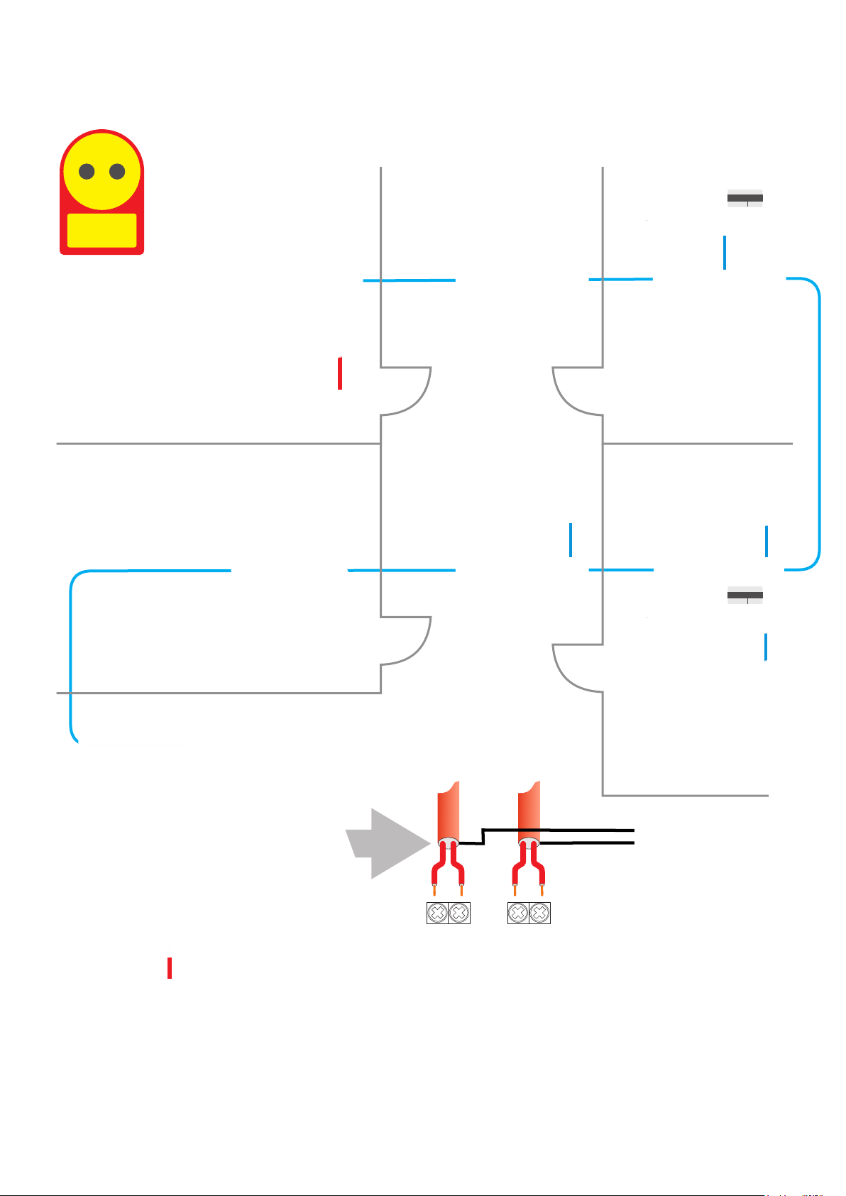
Booster Modules
2-Wire
Addressable
Mains Power
LPG
0-100%LEL
GAS DETECTOR
SN:20235-1-1 ADD:4110
Controller in Supervisors Office
ATEX Zoned Area
Power Booster
Cable Highway
Laboratory
Gas Bottle Store
LPG
0-100%LEL
GAS DETECTOR
SN:20235-1-1 ADD:4110
Mains Power
L2L2
L1L1
IN
OUT
Power boosters are used where the control panel cannot supply enough power
for the installed cable system. This may be due to the cable size being too small
resulting in a large volt drop over the cable run or that there are a large number
of devices drawing power. Booster modules are mains powered and can have an
internal battery backup if required. There are IN and OUT connections such that
the booster can be located at the end or part way down a cable run. Typically the
booster should be located at the point that the cable voltage drops to 22V DC or
if this is not known and boosters are planned from the start then located at the
end of a cable run.
43
Page 45

Cable Installation Standards
IGD Installations are undertaken to the requirements of BS7671 amendment 3 2015 , in particular Regulation
521.11.201. Note that this is not concerned with placement of gas detectors but relates to the installation
cabling requirements.
In Addition to BS6761 there are other relevant standards relating to cable segregation to minimise electrical
interference. In the UK are B6701:2016, which is safety standard, and BS EN 50174-2 Information technology
- Cabling installation - Part 2: Installation planning and practices inside buildings. BS EN 50174-2 is more
concerned about the electromagnetic compatibility issues (interference) between power and data cables,
rather than safety, but does state that safety issues take precedence over EMC issues. Within the Process
sector, the current guidance is BS6739:2009 - Code of practice for instrumentation in process control systems:
installation design and practice. For this standard IGD addressable systems are considered as Classification
4. Communications signals. This group includes fieldbuses, ethernet and other digital communication systems
such as CAN-based systems, and analogue/digital hybrids.
For our purposes a power cable is defined as above 50 V AC with a 10 A rating
In General
• Parallel runs of instrument cables and power cables should be avoided; however, where unavoidable,
adequate physical separation should be provided. A spacing of 200 mm is recommended from a.c. power
cables up to 10 A rating. For higher ratings the spacing should be progressively increased.
• Where a cross-over between signal and power cables is unavoidable, the cables should be arranged to cross
at right angles with separation of at least 200 mm maintained by positive means
• Power and gas detection cables are installed with a 200 mm separation wherever possible
• A 600 mm separation should be maintained between gas detection cabling and three phase power cables
• Where 200 mm separation isn’t possible then the reduced distances of Table 3 may be used
• A 50 mm separation must be included as defined in BS 6701
• A suitably earthed armoured power cable may be considered as ‘screened’ for the purposes of cable
segregation
• Failure to observe the above rules may lead to non compliance with The Electricity at Work Regulations 1989
and the EMC Regulations 2006 (SI 2006/3418) July 2007
• Failure to observe the above rules may lead IGD to withdraw any terms of Warranty associated with their
Gas Detection products for the specific installation concerned
The Following Examples Show Typical Cabling Schemes
44
Page 46
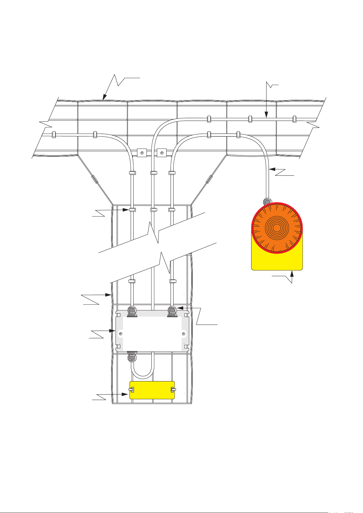
Typical Industrial Installation Scheme A
Cabling Fitted to Tray
Using Stainless Steel
Cable Ties
Ceiling Height Basket Tray
Typically 50mm
Preferred Cable Type 2
Core FP200 Min
1.5mmSQ, Check Cable
Sizing to IGD Guide
Accessory Cables
Typically Belden
Style Security Cable
4502 FE, Foil
Screen, 4 Core and
Drain Wire
0.75mmSQ
200mm Basket Tray
Fixed Using
Fasteners in
Accordance with
BS7671 amendment
3 Reg 521.11.201
Detector Node
Mounted to Basket
Tray Adaptor Plate
Tag Plate Available as an
Option to Match Control
Panel Screen Display
Location Tags. If
Required Order as TOCTAG-A and supply Table
of Required Tag
Descriptions
GAS ALARM
IGD Supplied Beacon
Sounders Supplied With
GAS ALARM Legend. 2
off Can be Run From
Each Detector Node
Snap Fit M20 Cable Glands
With Face Seal Supplied
With Detector Nodes (2 Per.
Additional Units Supplied in
5 Pack PN TOC-GLAND
TAG PLATE
Installation to be in Accordance with BS6761 amendment 3 Reg 521.11.201,
BS EN 7671:2008, BS EN 50174-2, BS EN 6701:2016 and BS6739:2009
45
Page 47

Typical Room Installation Scheme B Typical of Laboratories and Similar
Preferred Cable Type 2
Core FP200 Min
1.5mmSQ, Check Cable
Sizing to IGD Guide
Gas Detection Cabling Mounted to Existing
Containment For Fire/Security System
Accessory Cables
Cabling Fitted to Tray
Using Stainless Steel
Cable Ties
Suspended Ceiling Line
Typically Belden Style
Security Cable 4502
FE, Foil Screen, 4
Core and Drain Wire
0.33mmSQ
Tag Plate Available as an
Option to Match Control
Panel Screen Display
Location Tags. If
Required Order as TOCTAG-A and supply Table
of Required Tag
Descriptions
TAG PLATE
GAS ALARM
IGD Supplied Beacon
Sounders Supplied With
GAS ALARM Legend. 2
off Can be Run From
Each Detector Node
20mm Plastic Conduit Mounted
Using Metal Saddles and Fixings
to be Compliant With BS7671
amendment 3 Reg 521.11.201
Note Conduit Size Large Enough
For One FP200 Cable Run and
Accessory Cable Type 4502 FE
DO NOT Attempt to Enlarge
20mm Entries, This Will
Invalidate Warranty and
Damage Enclosure Sealing.
Installation to be in Accordance with BS6761 amendment 3 Reg 521.11.201,
BS EN 7671:2008, BS EN 50174-2, BS EN 6701:2016 and BS6739:2009
46
Page 48

Typical Room Installation Scheme E onto Dado Trunking Systems
TAG PLATE
20mm Plastic Conduit Mounted
Using Metal Saddles and Fixings
as Required to be Compliant
With BS7671 amendment 3 Reg
521.11.201
Tag Plate Available as an
Option to Match Control
Panel Screen Display
Location Tags. If
Required Order as TOCTAG-A and supply Table
of Required Tag
Descriptions
Note Conduit Size Large Enough
For One FP200 Cable Run and
Accessory Cable Type 4502 FE
DO NOT Attempt to Enlarge
20mm Entries, This Will
Invalidate Warranty and
Damage Enclosure Sealing.
Preferred Cable Type 2
Core FP200 Min
1.5mmSQ, Check Cable
Sizing to IGD Guide
Gas Detectors Mounted Above/Below Dado Style Wall Trunking
System.
Ensure Segregation From Mains Cabling. Ensure Cable is Only Run
in Trunking Data Compartments. Where Other Cables Use This
Compartment Ensure They Are Only Data Cables. Do Not Run Any
Mains Powered Loads Through The Data Section of the Trunking
Installation to be in Accordance with BS6761 amendment 3 Reg 521.11.201,
BS EN 7671:2008, BS EN 50174-2, BS EN 6701:2016 and BS6739:2009
47
Page 49
Installation Requirements for Samplers
Interconnecting Highway Cabling
For 2-Wire Addressable Systems:
For Safe Area Detectors Use 2
Core Cable 1.0 to 2.5mmSQ
Cable Depending on Distance.
Connect screens as indicated to
ensure screen continuity
Ensure Cable Screens are
Correctly Terminated and cables
are stripped to the enclosed
guide.
See Cable Calculator for Cable
Core Size vs Distance VS
Number of Devices
Drain Wires to Earth
Refer to TOC-750 Series Sampler
Manual for Full Details
TOCSIN
650 OR
750 Series
Controller
L1
L2
Port 1 to 4
Cable Screen or
Drain Wire
Tubing 6 x 4 Polyurethane
Other Tube Options Available
Do Not Exceed 20M
A variety of End of Line Termination
Points Are Available Contact IGD For
Further Details
48
Page 50

Installation Requirements for No-Volt Release Modules
No Volt-Release modules are fitted in situations where user intervention is required after resetting a gas
alarm before a signal is re-instated.
An example of its use would be where an output from the gas detection system is being used to control a
gas supply to a process. On detecting a gas leak the system shuts off the gas supply. If a normal relay is
used then on resetting the gas alarm the relay will also re-set and automatically bring back on the gas
supply. This may not be desirable. For example if the gas supply is feeding bunsen burners in a lab, then
there may be a number of open taps which would potentially leak unburnt gas if the supply automatically re-
instates. By fitting a no-volt release module to control the power to the gas valve this then requires manual
re-set of the supply before it is re-instated. With the module fitted, to re-instate the supply; there must be no
gas alarm or other alarm on the system controller, the e-stop on the no-volt release must be in the safe
position. At that point the supply can be manually re-instated.
TOCSIN
650 OR
750 Series
Controller
L1
L2
Port 1 to 4
Cable Screen or
Drain Wire
Base Add:
01
To next 2-Wire
L1L1
L2L2
device, not a
terminator is
required if this
is an end of
line device
Operation of the relay can be
either normally open or
normally closed configurable on
commissioning
Unit provides a volt free contact rated at max 30A 250V AC
Note this is a volt free contact designed to switch an external load powered
from an external supply.
49
Page 51

Notes
50
Page 52

International Gas Detectors Ltd
Triton House
Crosby Street
Stockport
Manchester
United Kingdom
SK2 6SH
Tel: +44 (0)161 483 1415
E-mail: [email protected]
Website: www.internationalgasdetectors.com
51
 Loading...