


0
2019
KURU PELET SOBASI
KULLANMA KILAVUZU
(AIR PELLET STOVE
USERGUIDE)
TRUVA & ABAN
Rev.No 2019.1.1

1

2
İçindekiler
GİRİŞ ......................................................................................................... 4
1. ÖNEMLİ UYARILAR ............................................................................... 5
1.1. Genel Güvenlik Uyarıları .................................................................. 5
1.2.
Çalıştırma Uyarıları
............................................................................. 6
2.
TEKNİK ÖZELLİKLER
.................................................................................. 7
3. YAKIT ÖZELLİKLERİ .............................................................................. 9
4. KURULUM .......................................................................................... 10
4.1. Kurulum Yeri Özellikleri ................................................................. 10
4.2. Elektrik Bağlantıları ....................................................................... 11
4.3.
Havalandırma ve Hava Akışı
................................................................ 11
4.4.
Baca Talimatları
................................................................................ 12
4.5.
Duman Borusu Talimatları
.................................................................. 13
4.6.
Uygun Baca Şekilleri ve Bağlantıları
....................................................... 14
5.
ÇALIŞTIRMA
......................................................................................... 16
5.1.
İlk Ateşleme
................................................................................... 16
6. YAKIT KALİBRASYONU ........................................................................ 17
7. KONTROL PANELİ ............................................................................... 19
7.1. Ekranda Görüntülenen Durum Açıklamaları ..................................... 20
7.2. Alarmlar ...................................................................................... 20
7.3. Kullanıcı Ekranı 1 .......................................................................... 22
7.4. Kullanıcı ekranı 2 .......................................................................... 23

3
8. TEMEL PARÇALAR VE BOYUTLAR ......................................................... 26
9. BAĞLANTI ŞEMALARI .......................................................................... 30
9.1. Anakart ....................................................................................... 30
9.1.1 Model: Efes ........................................................................... 30
9.1.2 Model: Gediz ......................................................................... 31
9.2 On/Off ........................................................................................ 32
10. BAKIM VE TEMİZLİK ........................................................................... 33
11. SORUNLAR, NEDENLERİ VE ÇÖZÜMLERİ .............................................. 35
12. VERİMLİ KULLANMA İÇİN ÖNEMLİ TALİMATLAR ................................... 37
13. ÖNERİLER VE GERİ BİLDİRİM .............................................................. 38
GARANTİ BELGESİ .................................................................................. 76
GARANTİ ŞARTLARI ................................................................................ 77

4
GİRİŞ
Değerli İFYIL Dostu;
İFYIL TERMO İKLİMLENDİRME SAN. Ve TİC. LTD. ŞTİ.
Fabrikasında titiz çalışmalar sonucu sizlere en verimli ürünleri
sunmayı arzuluyoruz. Bunun için, bu kılavuzun tamamını, ürününüzü
kullanmadan önce dikkatle okumanızı ve bir kullanım kolaylığı olarak
saklamanızı önemle rica ederiz.
Bilgilendirme
Bu sembol, sobanın doğru kullanımında önemli detayları vurgulamak
için
kullanılır. Uyarıları dikkate almazsanız, ürününüz düzenli ve doğru
çalışmayarak müşteri memnuniyetsizliği oluşabilir.
Dikkat
Bu sembol, ürünün çalışması esnasında doğabilecek ciddi tehlikeleri
ifade
etmek için kullanılır.
** Yanma Haznesi / Yanma Potası
** Helezon Motoru / Yakıt Besleme Motoru
** Mekanik Basınç Sensörü / Prosestat
ifadeleri aynı anlamları taşımaktadır.

5
1. ÖNEMLİ UYARILAR
1.1. Genel Güvenlik Uyarıları
•
Ürün kullanılmadan önce kullanma kılavuzu dikkatlice okunmalıdır.
•
Ürün kullanılacağı ülkenin mevzuatlarına uygun olarak kurulum
yapılmalı, gerekli emniyet tedbirleri alınmalıdır. Aksi halde İFYIL hiçbir
sorumluluk kabul etmeyecektir
•
Bu bir pelet sobasıdır. Lütfen yakıt olarak odun peleti kullanınız.
•
Soba yanma halinde iken yanma haznesine kesinlikle su ile müdahale
etmeyiniz.
•
Soba çalışırken sobanın fişini prizden çekmeyiniz. Önce sobayı kapatınız.
Ekranda ‘Kapalı’ yazdıktan sonra fişi prizden çekiniz.
•
Yanma potası temizlenmeden sobayı çalıştırmayınız.
•
Pelet tankı içerisine el koruyucusu yerleştirilmiştir. Soba çalışırken elinizi pelet
tankının içerisine sokmayınız.
•
Cihaz içerisinde çalışan elektronik ve mekanik parçaların zarar görmemesi için
tanımlı yakıt kullanılması gerekmektedir.
•
Soba kurulumu, elektrik bağlantıları ve test edilmesi işlemleri uzman teknik
personel tarafından yapılmalıdır.
•
Cihazda yapılacak herhangi bir değişiklik yetkili kişiler veya kurumlar
tarafından yapılmalıdır.
•
Sadece imalatçı firma tarafından tavsiye edilen yedek parça kullanılmalıdır.
•
Ürün sadece amaçlandığı şekilde kullanılmalıdır. Farklı kullanımlar tehlikelere
yol açar.
•
Ürünün yanlış kullanımı ya da uygunsuz bakım yapılması, yanma odasında
problemlere neden olabilir.
•
Sıcak yüzeylere direkt temastan kaçınınız.
•
Kapak açık ya da cam kırık olduğunda soba çalıştırılmamalıdır.
•
Ürün elektrikli bir cihaz olduğu için ıslak elle dokunmayınız. Herhangi bir işlem
yapılması gerektiğinde elektriği kesiniz.
•
İçerisinde elektriksel ekipmanın bulunduğu kapak ve bölümler, sistemin ana
enerjisi kesilmeden açılmamalıdır.
•
Bu ürün yetişkin insanlar tarafından kullanılmalıdır.
•
Katı yakıt bacası için ülke mevzuatlarına göre yerel kurallar veya normlar
varsa lütfen bu kurallara uyunuz. Eğer yerel normlar yoksa EN 13384 -1
standardına uyunuz.

6
1.2.
Çalıştırma Uyarıları
• İFYIL Pelet soba ve şömine sistemlerinin montajları; elektrik
bağlantıları ve kurulum şemasına uygun olarak yapılmalıdır.
• Pelet sobaları ev, ofis ve iç mekân için uygundur. Pelet sobaları
balkon, depo, banyo vs. gibi alanlara kurulmamalıdır. Lütfen ev içi
kullanımda mutfak, salon, antre gibi yerlerde; iç mekân kullanımında
kafeterya, restoran, işyeri gibi yerlerde kullanınız.
• Pelet sobaları, insanların uyudukları mekanlara kurulumu
yapılmamalıdır. Sobaların çalıştığı mekanlarda uyunmaması
önerilmektedir.
• Soba yanıcı gazların ve malzemelerinin bulunduğu ortamlara kurulumu
asla yapılmamalıdır.
• Sobanın uygun olmayan mekanlara kurulumundan dolayı yaşanacak
sorunlarda firmamız herhangi bir sorumluluk kabul etmemektedir.
• Kurulacak yerin ısı ihtiyacı hesaplanmalı ve buna uygun soba
seçimi yapılmalıdır.
• Cihaz, paylaşılan (ortak) bir baca sistemine kurulması için
uygun değildir.
• Pelet sobası mümkün olduğunca bacaya yakın monte edilmelidir. Baca
bağlantısı kısa olmalıdır.
• Soba ve baca bağlantıları mevcut bir bacaya ya da harici çift cidarlı bir
bacaya bağlanmalıdır. Boru iç çapı 80 mm olmalıdır.
• Oda termostatı kullanıyorsa, zeminden en az 1,5 m yüksekliğe
konulmalıdır. Sıcaklığın sürekli olarak değişiklik gösterdiği ve ısı
kaybının gözlendiği yerlere konulmamalıdır.
• Sobanın bulunduğu alanda:
o
Elektrik gücü 230V 50Hz ile donatılmıştır.
o
Topraklama yoksa hemen sağlanmalıdır.
o
Dışarıdan havalandırma yapılan bir ortam sağlanmalıdır.
o
Voltaj dalgalanmalarına karşı voltaj regülatörü kullanılması tavsiye
edilir.
• Oluşabilecek uzun süreli elektrik kesintilerine karşı güç
kaynağı kullanılması önerilir.
• Sobanın yakıt tankına tavsiye edilen maksimum yakıt doldurma
yüksekliği, tankın en üst seviyesinden 5 cm aşağısına kadardır.
• Yanma haznesi, küllük ve hava girişlerinin temizliği yapılmalıdır.

7
• Yakıtın kuru olup olmadığı kontrol edilmelidir. Yakıt nemli olmamalıdır.
• Peletler yanma potasına elle atılmamalıdır.
• Ateşleme düzgün gerçekleşmemişse soba kapatılıp pota
temizlenmelidir.
• Sobanın içi su ile yıkanmamalıdır.
• Baca borusunda yangın varsa, sobayı kapatın ve yetkili
mercilere başvurunuz.
• Sobanın ateşlemesi başarısız olursa başka bir yakıcı madde ile
ateşlemeye çalışmayınız.
• Duman çıkış kanallarını periyodik olarak kontrol ediniz.
• Bu ürün pişirme aracı değildir. Pişirme amacı ile kullanılamaz.
• Pelet tankına, pelet yakıttan başka yakıt konulmamalıdır.
• İlk çalıştırmada yükleme menüsünden, helezondan yanma
potasına yakıt gelene kadar yakıt yüklemesi yapılmalıdır.
• Yanma odasında yanıcı sıvı ve gaz asla kullanılmamalıdır.
• İfyıl sobaları açık alanlara, rutubetli alanlara, âtıl, dış ortamla
direkt temas halinde olan ortamlara kurulmamalıdır.
• Ürünün düzgün çalışmaması durumunda lütfen ürünü
kapatınız.
• Soba üzerinde bulunan koruyucu boyanın ilk yanma esnasında
oluşturduğu koku kısa sürelidir, bu durumda kapı ve pencereleri açınız.
Yukarıdaki şartları, garanti belgesinin sözleşmelerini ve krokilerin
gereğini yerine getirmeyen müşteriler hiçbir hak talep edemezler.
Herhangi bir durumda satıcınızla ya da İFYIL ile bağlantı
kurunuz.
2.
TEKNİK ÖZELLİKLER
Bu cihaz, tüm yerel (milli) mevzuata ve ilgili milli ve Avrupa
standartlarına uygun olarak imal edilmiştir.
❖
EN 14785: 2006- Odun peletleri tarafından ateşlenen konut alanı ısıtma
cihazları. Gereksinimler ve test yöntemleri
❖
2006 / 42 / AT- Makine emniyet yönetmeliği

8
Teknik Data
Ölçülen Değerler
Cihaz Tipi / Modeli ; Pelet Sobası
EFES
GEDİZ
Kapasite
Nominal ısı çıkışı
kW
10
8
Minimum ısı çıkışı
kW 3 2,4
Verim
Nominal ısı çıkışı
%
88
88
Minimum ısı çıkışı
%
89
89
Yakıt tipi
mm
Ø 6 / L:30 Odun
Peleti
Ø 6 / L:30 Odun
Peleti
Yakıt tüketimi (Min.- Maks.)
kg/h
0,75 - 2,5
0,60 - 2,00
Maksimum ısıtma hacmi
m3
287 (*)
230 (*)
Minimum baca çekişi
Pa
12 ± 2
12 ± 2
Yakıt tankı kapasitesi
kg - lt
23 - 38
17 - 28
Ağırlık
Soba
kg
137
127
Boyutlar
(En X Boy X
Yükseklik)
Soba
(dış kaset dahil)
mm
498x665x1150
498x665x1023
Yanma hava giriş
bağlantısı
mm
Ø 42.4
Ø 42.4
Baca bağlantısı
(iç çap)
mm
Ø 80
Ø 80
Elektrik tüketimi (ortalama)
W
230
230
Elektrik bağlantısı
Vac/Hz.
230/50
230/50
%13 O2 göre
CO emisyonu
Nominal ısı çıkışı
mg/m3
156,65
156,65
Minimum ısı çıkışı
mg/m3
267,84
267,84
Baca gazı
sıcaklığı
Nominal ısı çıkışı
⁰C
171,3
171,3
Minimum ısı çıkışı
⁰C
92,88
92,88
* Cihazın kurulduğu ortam şartlarına göre ısıtma hacmi değişiklik gösterebilir.
(Yalıtımlı bina için hesaplanmıştır)

9
3. YAKIT ÖZELLİKLERİ
Odun peleti, kuru odun tozlarının sıcaklık yardımıyla sıkıştırılması ile oluşur.
Materyalin kompakt oluşu ağacın kendi özünden gelir ve pelette yapışkan ya da
tutkal kullanılmasına gerek kalmaz. Odun çeşitlerine ve karışımlarına bağlı olarak
pelet çeşitlilik gösterir.
ENplus-A1+A2 kaliteye sahip odun pelet yakıtı kullanılmalıdır.
Tanımlar
ENplus-A1
ENplus-A2
Çap
6 mm
6 mm
Uzunluk
≤ 30 mm
≤ 30 mm
Net Kalorifik Değer
> 16,5 MJ/kg
> 3941 kcal/kg
> 16,5 MJ/kg
> 3941 kcal/kg
Nem İçeriği
< % 10
< % 10
Kül İçeriği
< % 0,7
< % 1,5
Yoğunluk
> 600 kg/m3
> 600 kg/m3
Pelet yakıt depolanması;
Peletler kuru, çok soğuk olmayan bölgede tutulmalıdır. Pelet torbalarının
depolanması ve taşınmasına özen gösterilmelidir. Pelet yakıtların
kırılmasından kaçınılmalıdır.
Sayın Tüketici;
İçeriğinde mdf, suntalem gibi kimyasal maddeler olan pelet kullanılması
halinde, cihaz zarar görebileceğinden dolayı ürününüz garanti kapsamı
dışına çıkar.
Cihazın içerisinde çalışan elektronik ve mekanik parçaların zarar
görmemesi için tanımlı yakıt kullanılması gerekmektedir.

10
4. KURULUM
• Bu ürün ev içi ve iç mekân kullanımına uygundur. Lütfen ev içi
kullanımda mutfak, salon, antre gibi yerlerde; iç mekân kullanımında
kafeterya, restoran, işyeri gibi yerlerde kullanınız.
• Balkon, banyo, depo gibi alanlara pelet sobası kurulmamalıdır. İç mekân
haricindeki kullanım durumunda, ısınma ile ilgili sorunlarda firmamız
sorumluluk kabul etmemektedir.
• Sobanın açık ve dış mekânlarda kullanımı ısı ve verim kayıplarına neden
olacaktır.
4.1. Kurulum Yeri Özellikleri
• Ahşap, lamine parke ve laminat parke olan zeminlerde soba altlığı (cam,
seramik, mermer vb.) konulması tavsiye edilir.
• Zemin düz ve sobanızın ağırlığını taşıyacak nitelikte olmalıdır.
• Yanabilen ürünler, yangın riskine karşı güvenli bir mesafede tutulmalıdır.
• Ürünü, yangın riskine karşı donanımlı yerlere kurunuz.
• Ürün, yanması için gerekli olan havayı sağlayabilecek şekilde
yerleştirilmelidir.
• Odanın hacmi 30 m³’ten az olmamalıdır.
• Sobaların kurulumu, insanların uyudukları mekanlara yapılmamalıdır.
Güvenli Minimum Mesafe
Yanmayan Duvarlar
A: ≥300 mm
B: ≥ 500 mm
C: ≥1100 mm (radyasyon alanı)
D: ≥1000 mm
E: ≥600 mm
Şekil 3-1- Güvenli minimum mesafe

11
Soba, yanabilen duvarlara yakın bir konuma yerleştiriliyorsa
duvara kesinlikle yalıtım yapılmalıdır.
•
Soba yanabilen döşeme üzerine yerleştirilirse, uygun yalıtım önlemi alınmalıdır.
•
Isıya duyarlı maddeleri (yanıcı, parlayıcı, patlayıcı) ve/veya nesneleri, soba
yanında muhafaza etmeyiniz.
•
Soba ağırlığını taşıyabilecek yüzeylere konumlandırınız. Soba konumunun
yakınındaki duvarın yanabilen malzeme olması durumunda ısı izolasyonu
yapılmalıdır.
4.2. Elektrik Bağlantıları
Elektrik kablosunu sobanın sıcak yüzeylerine
temas etmeyecek şekilde
takınız. Sobanın arkasında
bulunan açma/kapama şalterini açık konuma
getirerek sobanızı çalıştırınız.
Voltaj düzensizliğinin bulunduğu bölgelerde voltaj
regülatörü kullanılması gerekmektedir. Voltaj
regülatörü kullanılmamasından dolayı meydana
gelebilecek elektronik ve elektronik kart arızaları
garanti kapsamı dışındadır.
Sobanızı mutlaka topraklaması olan ve çalışan bir prizde kullanınız.
4.3.
Havalandırma ve Hava Akışı
• Sobanın kurulu olduğu odada, düzenli yanmayı sağlayacak kadar hava
bulunmalıdır.
• Sobanın bulunduğu yere dışarıdan temiz hava girişi sağlanmalıdır.
O : Kapalı
| : Açık

12
• Sobanın hava emiş borusu sürekli temiz hava akışı olabilecek bir ortama
(Dış ortama) hermetik boru ile bağlanması önerilmektedir.
• 300 cm² alt, 200 cm² üst menfez kullanılmalıdır. Bu menfezler
asla kapatılmamalıdır. Aksi halde büyük tehlike oluşturur.
• Sobanın kurulduğu alana temiz hava girişini sağlayan hava kanalları
varsa bakım ve temizliği yapılmalıdır.
•
Cihazı aşağıdaki ısıtıcılarla aynı ortama kurmaktan sakınınız;
o
B tipi gaz ısıtıcıları
o
Baca fanlı ya da fansız davlumbazlar
o
Cihazla aynı ortamda çalıştırılan aspiratör, problemlere sebep olabilir.
4.4.
Baca Talimatları
➢
Baca yangınlarının başlıca nedenleri;
•
Uygun olmayan boru seçimi
•
Yakıt tozları yanıcı özelliktedir. Uygun şartların oluşması durumunda kanallar
içerisinde tutuşarak yangına sebebiyet verebilirler.
➢
Bunlardan korunma yolları;
• Yakıt kalitesine bağlı olarak baca yılda en az 2 kere temizlenmelidir.
• Doğru ve uygun baca seçimi yapılmalıdır.
• Baca ve borularda duman sızdırmazlığının sağlanması ve izolasyonun
yapılmış olması gerekmektedir.
• Kurulum yapıldıktan sonra tutuşturma işlemi yapılmadan önce baca
temizliğinin yapılması gerekmektedir.
• Cihazın uzun süre kapalı kalma süresinden sonra, tekrar yanma
durumunda öncelikli olarak duman yolları ve baca tıkanıklığının kontrol
edilmesi gerekmektedir.
• Baca, çatı mahyasını en az 80 cm geçmelidir.
• Baca çapı 80 mm’dir.
• Baca bağlantıları yapılmadan önce baca testi yapılmalıdır. Eğer bacada
çekme sorunu var ise bu sorun giderildikten sonra baca bağlantıları
gerçekleştirilmelidir.
• Bacaya bağlanan soba boruları yatayda 2 m’den uzun olmamalıdır. Baca
borularında 90⁰ dirsek yerine 45⁰ dirsek kullanımı önerilir. (Soba için yer
seçimi bacanın bulunduğu en yakın noktaya göre belirlenmelidir.)
• Baca çevresinde türbülans oluşmaması için baca herhangi bir engelden
(yüksek bina, ağaç vb.) en az 10 m uzak olmalıdır.
• Rüzgârlı havalarda baca tepmesi ve yağmur suyunun baca içine akmasını
13
önlemek için baca başlığı kullanılmalıdır.
• Beton bloklar sıcaklık değişiminden etkilendiği için, beton olan dairenin
çatısı hava ile doğrudan temas halinde ise mutlaka yalıtılmalıdır.
• Baca temizleme kapağı baca borusunun altında olmalıdır, baca temizliği
buradan yapılmalıdır.
• Duman çıkışı için doğru ve yeterli bir baca sistemi (herhangi bir elektrik
kesintisi durumunda sobanızın içerisindeki dumanı dışarı atacak, geri
tepmeyecek nitelikte (2 Pa – 8 Pa) doğal çekişe sahip bir baca) gereklidir.
• Bacada oluşan kondens suyunun kazana ulaşmaması için gerekli
önlemler alınmalıdır.
• Baca çıkışının tıkanması veya kapatılması büyük tehlike oluşturur.
Soba kendi baca borusuna veya binanın dışında dikey olarak baca
dumanını binanın en
üst noktasına taşıyabilen bir bacaya bağlı
olmalıdır. Baca bağlantılarında, dikkat edilmeyen kaçaklar olur
ise ilk yanmada çıkan dumanlar bu kaçaklardan sızarak duvarda
islenmeye sebep olabilir, iz bırakabilir. Sızan duman ve/veya
alevler çok
sıcak olabildiği için yanmaya ya da yangına
sebep olabilir.
4.5.
Duman Borusu Talimatları
• Baca borusu bağlantıları oldukça önemlidir, bu nedenle bağlantıları dikkatli
bir şekilde yapılmalıdır. Duman borularının bağlantıları, garanti koşullarına
uygun olarak yapılması gerekmektedir.
• Asgari güvenlik açıklık yüzey kesiti %15 olmalıdır. Boruların yatay
bölümlerinde eğim yukarı doğru ve en fazla 3-5% olmalıdır (her metre için
3-5 cm). Yatay montajı yapılan borular 2 m’den uzun olmamalıdır.
• Soba baca boru bağlantı çapı 80 mm’dir.
• Borular ısıya, korozyona, yoğuşmaya dayanıklı malzemelerden yapılmış
olmalıdır.
• Duman gazının soğuyarak ağırlaşmasını ve tepmesini önlemek için soba
borusu pencere veya duvar delinerek uzatılmamalıdır.
• Baca boru standartlarına uygun olmayan baca kullanımlarından
oluşabilecek sorunlardan firmamız sorumlu değildir.

14
4.6.
Uygun Baca Şekilleri ve Bağlantıları
Soba bacasının ev dışında kalan kısmı mutlaka izolasyonlu olmalıdır. Eğer
bu izolasyonlar yapılmaz ise bacanın çekimi düştüğü için soba yanışında
sorunlar meydana gelecektir. Sobanızın herhangi bir elektrik kesintisi
durumunda içerisindeki dumanı dışarı atabilecek nitelikte doğal çekişe sahip
bir baca uygulaması yapılmalıdır.
Resim 3- Uygun baca şekilleri
Resim 4- Uygun olmayan baca şekilleri

15
** Uygun ve uygun olmayan baca şekilleri resimlerinde gösterilen sobalar temsilidir.
YUKARIDAKİ ESASLARA UYMAYAN DAİRELERDE VE İŞ YERLERİNDE KIŞIN
HER AN YANGIN ÇIKABİLİR VE KARBONMONOKSİT (CO) GAZI SIZINTISI
YAŞANABİLİR.
LÜTFEN YUKARIDAKİ ESASLARA UYALIM!
OLUŞABİLECEK DURUMLARDA FİRMANIN HERHANGİ HUKUKİ VE CEZAİ
MESULİYETİNİN OLMADIĞINI MÜŞTERİ
PEŞİNEN KABUL EDER. YUKARIDAKİ
GARANTİ BELGESİNİN SÖZLEŞMELERİNİ KROKİLERİN GEREĞİNİ YERİNE
GETİRMEYEN MÜŞTERİ HİÇBİR HAK VE TAZMİNAT TALEBİNDE
BULUNAMAZ.

16
5.
ÇALIŞTIRMA
5.1.
İlk Ateşleme
• Pelet besleyici, her ilk ateşlemede pelet tankının içi tam dolu
olamayabileceği için pelet tankından, pelet besleyiciye peletlerin
düştüğünden emin olun.
• Eğer birkaç yanma denemesinden sonra başarılı olunamıyorsa, pelet
yanma potasının doğru konumlandırıldığından emin olunuz.
• Ateşleyicinin potadaki deliğine yerleştiğinden ve yanma potasının yerine
tam olarak oturduğundan emin olunuz.
• Önceki yanmadan kalan pelet ve/veya kalıntıları, yanmaya engel teşkil
edebilir, lütfen kontrol ediniz. Bu kontrollerden sonra yine bir
anormallik bulunursa, soba bileşenleri ile ilgili bir sorun olabilir veya
yükleme doğru yapılmamış anlamına gelir.
• Uzun süreli kapalı kalma süresinin ardından, cihazınızı kullanmaya
başlamadan önce gerekli baca ve boru bağlantılarını tıkanmaya karşı
kontrol ediniz. Gerekli ise onarım işlemlerini yapınız/yaptırınız.
Soba üzerinde uyarı için yapıştırılmış etiketleri, sobayı
yakmadan önce sökünüz.
Sobanın ilk yanması sırasında odaya temiz hava girişi
sağlanmalıdır.
Soba üzerinde bulunan koruyucu boyanın ilk yanma esnasında
oluşturduğu duman ve koku kısa sürelidir, bu durumda kapı ve
pencereleri açınız.

17
6. YAKIT KALİBRASYONU
Cihazı devreye alma işleminde ve kullanılan peletin değiştirilme durumunda
kalibrasyon işlemi gerçekleştirilmelidir. İlk kalibrasyon işlemi (kurulum) teknik
servis tarafından yapılmak zorundadır. Kalibrasyon işlemi kazan soğuk ve
çalışmıyor iken yapılmalıdır.
Kalibrasyon işlemine başlamadan önce peletin düşüm noktasına peleti
tartabileceğiniz bir kap yerleştiriniz. (Besleme helezonu boş ise; ‘’ P3 ‘’ tuşuna
uzun basınız. Uzun basıldığında pelet beslemesi başlayacak ve yerleştirdiğiniz
kaba peletler gelecektir. Daha sonra ‘’ P3 ‘’ tuşuna tekrar basınız ve
yerleştirdiğiniz kabı temizleyip aşağıdaki işlemleri gerçekleştiriniz.)
‘’ P3 ‘’ tuşuna uzun basınız. Ardından pelet besleme aktif olacaktır ve 5 dakika
boyunca aralıksız pelet besleyecektir. Bu sürenin sonunda yükleme işlemini
tekrar gerçekleştiriniz. Bu 10 dakikalık yükleme sonundaki peleti tartınız. Bu
tartım sonucunu (Birim: Gram) tablodan karşılaştırınız. En yakın değer hangisi
ise onu seçerek P05 ve T03 parametre değerlerini değiştiriniz.
Bu işlemi yalnızca kurulum işleminden sonra kullandığınız peleti
değiştirir ve performans düşüşü hissederseniz uygulayınız.
İlgili değişikliklere aşağıdaki yolu izleyerek yapabilirsiniz.
P05 parametresini değiştirmek için; ‘’ P3 ve P4 ‘’ tuşlarına birlikte 3 saniye basılı
tutunuz. Çıkan menüden ‘’ tPAr ‘’ seçeneğini seçiniz. Sizden şifre girilmesi
istenecektir. Şifre için servisinizle görüşünüz. Sonrasında ‘’ tP01 ‘’ menüsünü
seçiniz. P2 ( + ) / P4 ( - ) tuşları ile P05 parametre değerine ulaşabilirsiniz.
T03 parametresini değiştirmek için; ‘’ P3 ve P4 ‘’ tuşlarına birlikte 3 saniye basılı
tutunuz. Çıkan menüden ‘’ tPAr ‘’ seçeneğini seçiniz. Sizden şifre girilmesi
istenecektir. Şifre için servisinizle görüşünüz. Sonrasında ‘’ tP05 ‘’ menüsünü
seçiniz. P2 ( + ) / P4 ( - ) tuşları ile T03 parametre değerine ulaşabilirsiniz.

18
Kullanıcı kalibrasyon işlemi dahilinde bu iki parametre
dışında hiçbir parametreyi değiştirmemelidir. Aksi
durumda oluşabilecek performans kaybından kullanıcı
sorumludur.
Tüm bu işlemlerin servis tarafından yapılması tavsiye edilir.
Model: Efes/Gediz
Gr/10 dk
P05
T03
500
3,9
236
550
4,2
210
600
4,6
191
650
5
175
700
5,4
163
750
5,8
152
800
6,2
142
850
6,6
134

19
7. KONTROL PANELİ
Ana ekranda görüntülenen
değerler:
Görüntü D1
: zaman, sistem
durumu, hatalar, Menu, altmenu,
parameter değeri
Görüntü D2
: güç, parameter kodu
Görüntü D4
: Ana sıcaklık,
parametre kodu
Tuş
Fonksiyon
Bir kere basıldığında
Uzun basıldığında
P1
Bilgilendirmeler / Menüden çıkış
Ateşleme / Söndürme / Hata giderme
P2
Sıcaklık değiştirme (+) / Değer artırma
Pelet yükleme düzeltmesi
P3
Yanma güçlerinin değiştirme / Değer
kaydetme
Manuel pelet yükleme
P4
Sıcaklık değiştirme (-) / Değer
düşürme
Yanma Fanı hız düzeltmesi
Led
Fonksiyon
Led
Fonksiyon
L1 Isıtma fanı aktif
L5 G
Günlük program seçili
L2 Helezon motoru aktif
L6 S Haftalık program seçili
L3 Ateşleyici aktif
L7 W Hafta sonu program seçili
L4
Ayarlanan sıcaklığa
ulaştı
ESC
G S W
L1
L5
L4
D2
D4
D3
D1
P2
P1
P4
P3
L6
L7
L2
L3

20
7.1. Ekranda Görüntülenen Durum Açıklamaları
Durum
Kod
Durum
Kod
Durum
Kod
Kapalı
-
Ateşleme-Değişken
ateşleme
On 4
Güvenlik
SAF
Kontrol
ChEc
Stabilizasyon
On 5
Söndürme
OFF
Ateşleme-Ön
Isıtma
On 1
Çalışma modu
-
Blok
Alt
Ateşleme-Ön
yükleme
On 2
Modülasyon
Mod
Ateşleme
kurtarma
rEc
Ateşleme-Sabit
ateşleme
On 3
Bekleme
Stby
7.2. Alarmlar
Tanımlama
Kod
CP
Kazan su sıcaklığı aşırı yüksek hatası (Sistem kapalı iken de bu alarm aktif olur.)
Er01
Prosestat hatası
Er02
Düşük baca sıcaklığında söndürme
Er03
Yüksek baca sıcaklığında söndürme
Er05
Fan enkoder hatası: Enkoder sinyali yok
Er07
Fan enkoder hatası : Baca fanı ayarlaması yapılamadı
Er08
Uzun süreli elektrik kesintisinde gün ve tarih doğru değil hatası
Er11
Ateşleme hatası
Er12
Elektrik kesintisi
Er15
Kontrol paneli ( RS485 ) bağlantı hatası
Er16

21
Pelet bitti hatası
Er18
Pota temizleme motor hatası
Er25
Servis hatası
SErU
Tanımlama
Kod
İlk sistemin kendi kendini kontrol ettiği durumda problarda problem olduğunda
görünür.
Sond
Bu mesaj sobanın temizlenme zamanının geldiğini ifade eder.
CLr
Eğer soba ateşleme esnasında harici bir cihaz tarafından kapatılırsa ( Ön
Yükleme evresinden sonra ) OFF dEL mesajı görüntülenir. Sistem sadece
çalışma moduna giderken duracaktır.
OFF
dEL
Periyodik temizleme yapılıyor anlamına gelir.
PCLr
Görüntü
Birim
Tanımlama
tF
[°C]
Baca sıcaklığı
tA
[°C]
Oda sıcaklığı
tr
[°C]
Oda termostat sıcaklığı
UF
[rpm]
Baca fan hızı
Co
[s]
Pelet besleyici aktif süresi
St
[h]
Sistem ‘Servis’ uyarısı göstermesine kalan zaman
St2
[h]
Sobayı temizleyin uyarısına kalan zaman.
FC **
Yazılım kodu ve revizyonu: FYSr02000001.x.y

22
7.3. Kullanıcı Ekranı 1
Yanma Güç
Ayarı
P3 tuşuna basınız: D2 kısmı yanıp sönecektir. Tekrar aynı tuşa
basıldığında değerler değişecektir. 5 saniye sonra yeni değer
aktif olacak ve seçilen değeri görebilirsiniz.
Manuel
Pelet
Yükleme
P3 tuşuna uzun basıldığında manuel pelet yükleme aktif olacaktır
ve yakıt besleme sürekli olarak çalışacaktır. Altta Yüklemeyi
gösterir, yukarı ekranda yükleme yapılan zamanı gösterir.
Yüklemeyi durdurmak için herhangi bir tuşas basınız. Yükleme
300 saniye sonunda otomatik olarak duracaktır.
Pelet
yükleme
düzeltme
P2 tuşuna uzun basıldığında bu fonksiyon aktif olacaktır.
(Değişiklik yapabilmek için iki defa tekrarlanmalıdır). Alt ekranda
PELL ifadesi görünür, yukardaki ekranda değer görünür. P2/P4
tuşları ile değer arttırılabilir ya da azaltılabilir; varsayılan değer ‘0’
dır. 5 saniye sonra yeni değer kaydedilmiş olur ve normal ekrana
geri dönder.
Baca fanı
düzeltme
P4 tuşuna uzun basıldığında bu fonksiyon aktif olacaktır.
(Değişiklik yapabilmek için iki defa tekrarlanmalıdır). Alt ekranda
Uent ifadesi görünür, yukardaki ekranda değer görünür. P2/P4
tuşları ile değer arttırılabilir ya da azaltılabilir; varsayılan değer ‘0’
dır. 5 saniye sonra yeni değer kaydedilmiş olur ve normal ekrana
geri dönder.
Sıcaklık
ayarı
Anlık değer alt ekranda görüntülenir.

23
7.4. Kullanıcı ekranı 2
Bu menüye erişebilmek için P3 ve P4 tuşlarına aynı anda basınız.
Isıtma
fan gücü
(Air)
Bu menu ısıtma fan gücünün değiştirilmesine izin verir.
Isıtma
arka fan
gücü
(CAn)
Bu menu ısıtma arka fan gücünün değiştirilmesine izin verir.
Oda
termost
atı (rEM)
Bu menu oda termostatını ayarlamaya izin verir. (Sadece Efes model soba
için geçerlidir)
Krono
(Cron)
Bu menu sobanın açılma ve kapanma zamanlarını ayarlamaya olanak tanır.
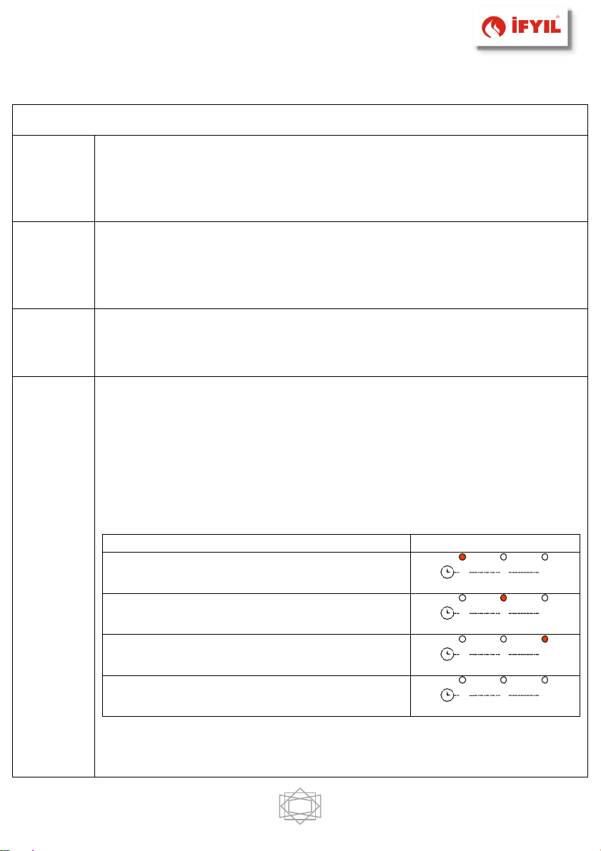
2 adet alt menüsü vardır.
-Krono aktifleştirme menüsü
Bu menu krono ayarlarını seçmeye izin verir.Ekranda ModE görüntülenir.
YÖNTEM
LED
Gior: Günlük Program
WG S
Sett: Haftalık Program
WG S
FiSE: Haftasonu Programı
WG S
OFF: Program aktif değil.
WG S
-Programlama Zaman Aralıkları Menüsü

24
Ekranda ProG yazısı belirir. 3 adet altmenüden oluşur, Her bir program
yöntemi:
Günlük
: Haftanın her günü için ayrı ayrı 3 adet program yazılabilir.
Haftalık
: Haftanın bütün günleri için yazılan program geçerli olur
Haftasonu
: Pazartesi-Cuma ya da Cumartesi-Pazar için 3 program
ayarlanabilir.
Görüntüleme
Görüntü
Günlük yöntem: Gün
Mo
Haftalık yöntem: Pazartesi-Pazar
MS
Haftasonu yöntemi: Pazartesi-Cuma
Cumartesi-Pazar
MF
SS
Açık olduğunda ekranın alt kısmında D2nin olduğu yerde
sağdaki gibi görüntülenir.
1I M o
Kapalı olduğunda ekranın alt kısmında D2nin olduğu yerde
sağdaki gibi görüntülenir.
1I Mo
Talimatlar
Her bir program için açılacağı ve kapanacağı zaman ayarlanması
gerekmektedir.
TANIMLAMA
GÖRÜNTÜ
1) İstenilen Alt-Menüye kadar P2 / P4 tuşlarına
basarak ilerleyin ve P3 tuşuna basın
G i o r n
2) Mevcut 3 programdan birini seçmek için P2 / P4
tuşlarına basın
1I Mo
3) P1 tuşuna 3 saniye basın
0 0 . 0 0

25
4) Ateşleme zamanını seçiniz
1I M o
5) Değişiklik moduna girmek için P3 düğmesine basın:
seçilen değer (saat veya dakika) yanıp söner. Değeri
değiştirmek için P3 tuşuna saat ve dakika arasında
geçiş yapın, P2 / P4 ile arttırıp azaltılabilir.
0 1 . 0 0
1I M o
6) P3 tuşuna basarak kaydediniz
2 1 . 3 0
1I Mo
7) P2 tuşu ile Kapalı Zamanlayıcıyı seçin ve 5.
noktadan işlemleri tekrarlayın.
0 0 . 0 0
1I Mo
Her zaman ayarı 15 dakikalık zaman aralıkları ile ayarlanabilir.
Saat
(oroL)
Bu menu saat ve tarihi ayarlamaya izin verir. Ekran şekildeki gibi
görüntülenir.
Açıklama
Görüntü
Düzenlemeye girmek için P3 düğmesine basın. Seçilen
değer (saat, dakika, gün) yanıp söner. Değeri değiştirmek
için P2 / P4 tuşlarını kullanın.
Diğer parametreleri değiştirmek için P3 düğmesine basın.
Ayarlanan değeri kaydetmek için tekrar P3 düğmesine
basın.
0 7 . 3 3
Mo
Kumand
a (TELE)
Bu menu uzaktan kumandayı aktif etmeye izin verir.
Temizlik
sıfırlama
(rCLr)
“Sistem bakımı 2” yi sıfırlamak için kullanılır.
Teknik
Menu
(TPAr)
Bu menu Teknik menüye erişim sağlar. Sadece Teknik servis bu menüye
erişebilir ve şifre ile korunmaktadır.

26
8. TEMEL PARÇALAR VE BOYUTLAR
Model: Efes

27
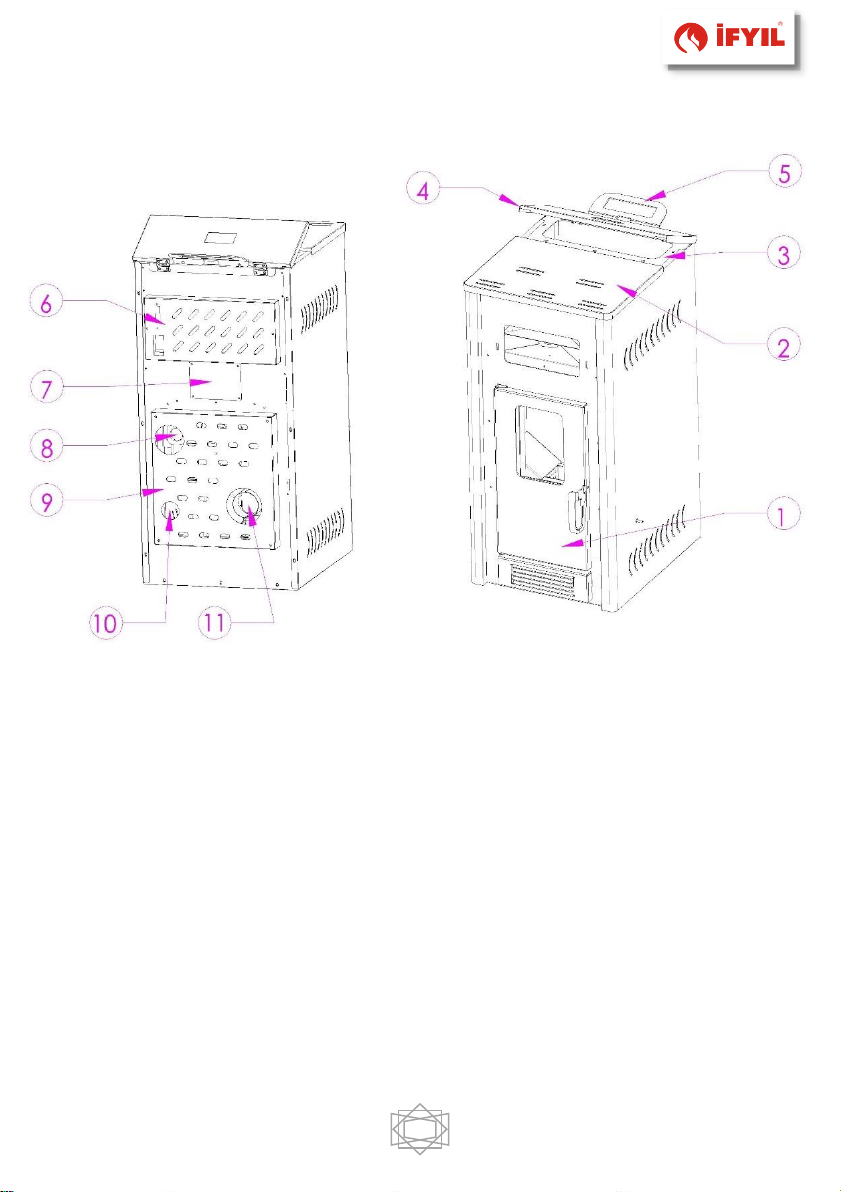
Model: Efes
1. Yanma odası kapak
2. Üst kapak
3. Üst sac
4. Pelet tankı kapağı
5. Kontrol paneli
6. Anakart müdahele kapağı
7. Pelet tankı müdahele kapağı
8. Ortam fanı
9. Servis müdahele kapağı
10. Primer yanma hava girişi (ø50 mm)
11. Baca çıkışı (ø80 mm)

28
Model: Gediz

29
Model: Gediz
1. Yanma odası kapak
2. Üst kapak
3. Üst sac
4. Pelet tankı kapağı
5. Kontrol paneli
6. Anakart müdahele kapağı
7. Pelet tankı müdahele kapağı
8. Servis müdahele kapağı
9. Primer yanma hava girişi (ø50 mm)
10. Baca çıkışı (ø80 mm)

9. BAĞLANTI ŞEMALARI
9.1. Anakart
9.1.1 Model: Efes

9.1.2 Model: Gediz

32
Oda Termostatı (Efes)
Anakart üzerinde bulunan 24-25 numaralı girişlerde (IN 3) köprü
kaldırılarak, yerine Oda Termostatı bağlanabilir.
9.2 On/Off
Model: Efes/Gediz

33
10. BAKIM VE TEMİZLİK
Sobanızın tüm temizlik işlemlerini, sobanız yanmıyor iken (soğuk
halde iken) ve elektrik bağlantısı kesilmiş konumda yapınız.

34
Türbülatör – Duman Boruları Temizliği;
–
Türbülatör temizliğinde 1 numaralı kapağı (şekil 9-3) kapalı olmalıdır.
–
Şekil 9.1’de görülen 1 numaralı üst kapağı çıkarınız.
–
Şekilde 9.1’de görülen 2 ve 3 numaralı türbülatör kollarını aşağı ve yukarı doğru
hareket ettiriniz.
–
Türbülatörler iyice temizlenene kadar devam ettiriniz.
–
Sonra Şekilde 9.1’de görülen üst kapağı kapatınız.
–
Şekil 9.3 de gösterilen 1 numaralı parçanın vidalarını sökünüz. Türbülatörlerden
dökülen küller 1 numaralı bölümde toplanır. Bu bölümü pelet kalitesine bağlı
olarak en az ayda 2 defa temizleyiniz.
Yanma potası Temizliği;
Günlük basit bir görsel kontrol ile potada cüruf birikimi olup olmadığını kontrol ediniz.
Cüruf var ise yan tarafta bulunan çekme kolunu çekerek potayı temizleyiniz.
Daha sonra kolu itiniz.
Küllük Temizliği
Şekil 9-2’te görülen 2 numaralı küllüğü çıkarınız. Temizleyip yerine yerleştiriniz. Bu
işlemi haftada bir kez yapabilirsiniz.
Günlük ve haftalık temizlik;
•
Sobanızın camını nemli ve yumuşak bez ile yüzey temizleyici kullanarak temizleyiniz.
•
Sobanızın temizliğini yaparken yanıcı, patlayıcı, parlayıcı vb. tehlike oluşturabilecek
kimyasallar kullanmayınız.
•
Cihazın '' 200 saat '' çalışma süresi tamamlandığında, soba bakımının
yapılması için teknik servis ile irtibat kurunuz.
•
Boyalı parçalar üzerine veya kapak contaları (sızdırmazlık fitilleri vs.) üzerine
temizlik spreyi sıkmayınız.
Soba 200 saatte bir ekranda “CLr” uyarısı verecektir. Sistem
periyodik olarak sesli bir sinyal verir. Bu uyarıyı ‘’ rCLr ‘’ sekmesinden
kaldırabilirsiniz. Bu menüye erişmek için; P3 ve P4 tuşlarına bir kez
basınız. Çıkan menüden ok tuşları ile (P2/P4) ‘’ rCLr ‘’ menüsüne P3
tuşu ile giriniz. P3 tuşuna bir kez basıldığında ekranda ‘’ rES ‘’ yazısı
gelecektir. Bir kez daha P3 tuşuna basıldığında ekranda ‘’ SURE ‘’
yazısı yanıp sönecektir. Tekrar P3 tuşuna basıldığında alarm ortadan
kalkacaktır. Bu işlemler sadece soba kapalı iken yapılabilir.
11. SORUNLAR, NEDENLERİ VE ÇÖZÜMLERİ
PROBLEMLER
MUHTEMEL NEDENLER
ÇÖZÜMLER
Soba çalışmıyor.
1. Elektrik arıza veya voltaj eksikliği
2. Sigorta atmış.
1. Elektrik soketi ve ana şalterin çalışır
konumda olduğundan emin olun, takılı
olup olmadığını kontrol ediniz.
2. Sigortayı değiştiriniz.
Soba da ki Alev kendiliğinden sönüyor
ve/veya soba otomatik olarak duruyor.
1. Pelet haznesi boş.
2. Pelet besleyicisi çalışmıyor.
3. Kapı tam kapalı değil.
4. Uygun olmayan pelet.
5.
Yanma potası kirli.
1. Pelet haznesini doldurunuz.
2. Teknik servisi arayınız.
3. Kapıyı kapatınız.
4.
Üretici tarafından tavsiye edilen pelet
türünü kullanınız.
5. Kılavuz da belirtildiği gibi yanma
potasını temizleyiniz.
Soba birkaç dakika boyunca çalışıyor ve
daha sonra sönüyor.
1. Ateşleme döngüsü
tamamlanmamıştır.
2. Ateşleyici, Sıcaklık sensörleri arızalı
veya bozuk.
3. Duman kanalı tıkalı
1. Sobayı kapatıp yeniden çalıştırınız.
2.
Teknik servisi arayınız.
3. Duman kanallarını temizleyiniz.
Peletler yanma potasına az geliyor.
1.
Pelet haznesi boş.
2. Pelet Besleyici vida ve/veya
talaş(toz) tarafından engellendi.
3.
Motor ya da elektronik kart arızalı.
1. Pelet haznesini doldurunuz.
2. Pelet besleyiciyi talaş(toz) vida gibi
engellerden kurtarınız.
3. Sorun çözümlenmezse teknik servisi

arayınız.
Soba alarm veriyor.
1. Soba bir problem algıladı.
1. Açma/ kapama düğmesine basılı
tutarak sobanın kendini kontrol
etmesini sağlayınız. Hata giderilirse
soba kapanma durumuna geçer.
Peletler yanma potasına yığılmakta,
kapak camı çok çabuk kirleniyor ve alev
boyu kısa görülüyor.
1. Yetersiz yanma havası gelmektedir.
2. Peletler nemli veya uygun kriterleri
sağlamayabilir.
3. Baca fanı arızalı olabilir.
1. Odanın sürekli temiz hava ile
yenilenebilir olduğunu kontrol ediniz.
Sobanın arkasındaki temiz hava
girişinin tıkalı olup olmadığı kontrol
edilmelidir.
2. Pelet tipini değiştiriniz. Yanma
potasını temizleyin ve hava
kanallarının açık olduğundan emin
olunuz. Kapak fitillerinin tam olarak
yapıştığını kontrol edin. Pelet yanma
potasının bulunduğu yere doğru
oturduğunu kontrol ediniz.
3. Teknik servisi arayınız.
Duman Baca fanı tahliye motoru
çalışmıyor.
1. Baca fanını besleyen motor
bozulmuş olabilir.
2. Elektronik kart arızalı olabilir.
1. Teknik servisi arayınız.

37
12. VERİMLİ KULLANMA İÇİN ÖNEMLİ TALİMATLAR
• Sobayı ateşleme konumuna getirmeden önce küllüğün ve yanma potasının
temiz ve yerine doğru yerleştirilmiş olduğundan emin olunuz.
• Temizleme fırçası ile sobanızın iç kısmını temizleyiniz, dışını ise temiz bir bez
yardımı ile temizleyiniz.
• Sobanın kullanılacağı ortamın ısı yalıtımlı olması önerilir.
• Sobalarımız ev ve iş yeri gibi kapalı alanlar haricinde (balkon, depo, kiler vb.)
kullanılmaması gerekmektedir. Aksi halde ısınma ile ilgili sorunlarda firmamız
sorumluluk kabul etmemekte olup, ürün garanti kapsamı dışına çıkmaktadır.
Sobanın açık ve dış mekanlarda kullanımı ısı ve verim kayıplarına neden
olacaktır.
• Yakıt olarak, ø 6 mm L:30 mm odun peleti kullanılmalıdır.
• Yakıt tankına peletten başka yakıt konulmamalıdır.
• Soba açıkken, sobayı kapalı konuma getirmek için kapatma düğmesine
basınız. Kesinlikle prizden fişi çekmeyiniz.
• Yakıt tankının alt seviyesinden itibaren 20 cm kadar yükseklikte pelet
kaldığında yeniden yakıt doldurunuz.
• Yakıt tankı tam doldurulmamalıdır, yakıt deposunun kapağından itibaren 5
cm boşluk bırakılmalıdır.
• Baca kurulumu talimatlara uygun olarak yapılmalıdır.
• Yıllık bakım sobanızın ömrünü uzatır.
• Soba ve baca bakım-temizliği kullanılan peletin kalitesine bağlı olarak yılda
en az 2 (iki) kez yapılmalıdır.

38
13. ÖNERİLER VE GERİ BİLDİRİM
• Lütfen kullanma kılavuzu ve montaj şemalarını dikkatlice okuyunuz.
• Yılda bir kez, soba yetkili bayi tarafından kontrol edilmelidir.
• Sobanın kapısı açık iken sobayı açmayınız veya kapatmayınız.
• Yangın durumunda elektrik fişini çekiniz. Odayı havalandırmak için pencere
ve kapıyı açınız. Acil yangın hizmetlerini (itfaiye) arayınız.
• Lütfen sadece tavsiye edilen yakıtları kullanınız.
• Lütfen kullanıcı talimatlarını uygulayınız.
İFYIL TERMO İKLİMLENDİRME SAN. Ve TİC. LTD. ŞTİ.
İLETİŞİM BİLGİLERİ
Tel: +90 (362) 266 94 43
Faks: +90 (362) 266 94 43
E-mail: info@ifyil.com.tr
Adres: Yeni Cami Mah. 3. Cad. Kavak OSB Kavak/ SAMSUN/TÜRKİYE
İFYIL KALİTESİNİ SEÇTİĞİNİZ İÇİN TEŞEKKÜR EDERİZ…!
Servis aramaları
Teknik servis çağrıları için www.ifyil.com.tr adresini ziyaret ediniz.
Ürünün ya da herhangi bir yedek parçasının yanlış kullanılması
ve/veya izinsiz değiştirilmesi durumunda doğabilecek sorun ve
arızalardan firmamız sorumlu değildir.
Herhangi bir yedek parça değişimi için yalnızca orijinal İFYIL
yedek parçaları kullanılmalıdır.
* İFYIL ürünlerinin özellik, tasarım ve malzemelerinde değişiklik yapma hakkını
saklı tutar.

39
Contents
INTRODUCTION
.......................................................................................... 41
1. IMPORTANT NOTICE .......................................................................... 42
1.1. General Safety Warnings .............................................................. 42
1.2.
Operating Warnings
.......................................................................... 43
2.
TECHNICAL SPECIFICATIONS
.................................................................... 44
3. FUEL INFORMATION ........................................................................... 46
4. INSTALLATION ................................................................................... 47
4.1. Operating Environment ................................................................. 47
4.2. Electrical Connections ................................................................... 48
4.3. Ventilation And Air Flow ................................................................ 48
4.4. Chimney Instructions .................................................................... 49
4.5. Smoke Pipe Instructions ............................................................... 50
4.6. Suitable Shapes Of Chimney ......................................................... 51
5. OPERATING ....................................................................................... 53
5.1. First Fire ...................................................................................... 53
6. FUEL CALIBRATION ............................................................................ 54
7. CONTROL PANEL ................................................................................ 56
7.1 Status Descriptions Displayed on the Screen ................................... 57
7.2 Alarms ........................................................................................ 57
7.3 User Screen 1 .............................................................................. 59
7.4 User Screen 2 .............................................................................. 60

40
8. MAIN PARTS AND DIMENSIONS........................................................... 63
9. CONNECTION SCHEMAS...................................................................... 67
9.1. Mainboard ................................................................................... 67
9.1.1. Model: Crystal ....................................................................... 67
9.1.2. Model: Thermal ..................................................................... 68
9.2 On / Off ...................................................................................... 69
10. MAINTENANCE and CLEANING ............................................................ 70
11. PROBLEMS, CAUSES and SOLUTIONS................................................... 72
12. SIGNIFICIANT INSTRUCTIONS for EFFECTIVE USING ............................ 74
13. SUGGESTIONS and FEEDBACK............................................................. 75
CERTIFICATE OF WARRANTY .................................................................. 79
WARRANTY CONDITIONS ........................................................................ 80

41
INTRODUCTION
Dear Friend of İFYIL;
We, İFYIL TERMO İKLİMLENDİRME SAN. Ve TİC. LTD. ŞTİ. manufacture the
most efficient
hydro pellet stoves with utmost care for our distinguished
customers.
Please read this user guide carefully before starting to use our stove and
keep it as a reference in
any case.
Information
This symbol high lightens the significant details for correct usage of
stove. If the warnings are ignored, product will not be fully correct &
regular and this can cause customer not satisfaction.
Attention
This symbol high lightens the possible serious risks during operation
of stove. So, this user guide should be read carefully before using
the stove and utmost attention should be paid to the warnings.
** Combustion Chamber / Combustion Pot
** Pellet Feeder Motor / Fuel Supply Motor
** Mechanical Pressure Switch / Prosestat
These side-by-side expressions have the same meanings.

42
1. IMPORTANT NOTICE
1.1. General Safety Warnings
•
Please, carefully read the manual to get the best yield from the pellets
stove
•
The product should be installed in accordance with the legislation of the
country in which it will be used and the necessary safety precautions
should be taken. Otherwise IFYIL will not accept any responsibility.
•
This is a pellets stove. Please only use wood pellets as fuel.
•
Please do not put water on the stove during operation.
•
Please do not plug off while operating. Please initially switch off. This operation is very
vital
for the cooling of the stove.
•
Please do not operate the stove without cleaning the combustion pot.
•
The hand protector has been placed inside the pellet tank. Please do not put your
hand inside
while the stove is working.
•
It is necessary to use defined fuel in order not to damage the electronic and
mechanical
parts working in the device.
•
Installation, electrical connection and function test operations
must only be carried out by authorised and qualified technical
personnel.
•
Any change on the stove should be done by authorized persons.
•
Spare parts should only be used by the recommended manufacturer.
•
A bad use or improper maintenance of the product can bring to
explosion in the combustion chamber.
•
The product should only be used as intended. Different uses lead to danger.
•
Do not touch the product with wet hands as it is an electrical device. If any action is
required,
cut off the electricity.
•
This product should be used by adults only.
•
The stove must not be operated while the door is open or the glass is broken.
•
Do not open the covers and sections where the electrical equipment is
located, without disrupting the main energy of the system.
• Please comply with these rules if there are local rules or norms for the
solid fuel chimney according to country regulations. If there are no local
norms, comply to EN 13384-1.

43
1.2.
Operating Warnings
•
Assembly of İFYIL pellet stoves and fireplaces; Electrical connections and
installation should be done in accordance with the scheme.
•
Pellets stoves are for houses, office and internal places.
•
Pellets stoves must not be used in: Balcony, warehouse, bathroom etc.
•
Pellet stoves should not be installed in the places where people sleep. Stoves
are recommended to be avoided in places where sleep.
•
The stove should never be installed in the presence of flammable gases and
materials.
•
We do not accept any responsibility for any problem due to the outdoor
installation of
stove.
•
The heat requirement of the place to be installed must be calculated and the
appropriate
stove selection must be made.
•
Stove is not suitable for a shared (common) chimney system.
•
Pellets stove must be installed as close as possible to the chimney. (Chimney
connection
must be short as possible.)
•
Stove and chimney connector must be connected to an existing chimney or an
external double-walled chimney. (
Flue pipe inner diameter must be 80 mm
).
Chimney height 80
cm higher than the roof ridge.
•
Extractor fan throw out the combustion gas and chimney easily throw out smoke.
•
Correct and efficient chimney system is necessary to throw out the smoke (no
reverse
smoke and throw out the smoke of stove in case of any blackout).
•
Chimney cleaning cap must be under chimney pipe and cleaning must be done from
here.
•
If the room thermostat is to be used, it should be installed 1,5 metres higher than
floor. It should not be installed in a place where temperature change and loss are
experienced.
•
The place where stove must be equipped with:
o
Electrical power 230V 50Hz.
o
Grounding plug.
o
If there is no ground connection it should be provided immediately.
o
Fresh air must be provided from outside.
o
Please, use the Voltage regulator for voltage fluctuation.
•
Power supply should be used during long term power outages.
•
Fuel tank should not be loaded fully, 5 cm clearance should be left from the top.

44
•
Burning pot, ash box and air inlets should be cleaned.
•
Fuel should be checked if wet or not. Fuel should not be damp.
•
Pellets should not be thrown manually into the combustion pot.
•
If the ignition is not properly done, the stove should be turned off and
cleaned.
•
The inside of the stove should not wash with water.
•
If there is a fire in the chimney pipe, close the stove and contact the
competent authorities.
•
If the ignition fails, do not burn it with another burning substance.
•
Periodically check the smoke outlet duct.
•
This product is not a cooking appliance. Don’t use for cooking.
•
No other fuel from the pellet fuels should be placed in the pellets tank.
•
The stove heat will yield losses of the use of open covers and exterior.
•
Fuel loading must be performed from the test menu to the fuel tank from the helix
to the burning
pot at the first start.
•
Never use flammable liquids and gases in the combustion
chamber.
•
İfyıl pellets stoves must not be installed into open, moisture, idle
places etc. Stove
must not have direct contact with outdoor
ambient.
•
If the product does not work properly, please turn it off.
•
The odour created by the protective paint on the stove during the first
combustion is short term, in this case open the doors and windows.
Customers not obeying the above requirements and schemas
cannot claim any right for any problem. In any case, contact your
dealer or IFYIL.
2.
TECHNICAL SPECIFICATIONS
•
This device should be installed in accordance with the related regulation and EU
standards.
EN 14785 : 2006 - Residential space heating appliances fired by wood
pellets. Requirements and test methods.
2006 / 42 / EC- Machinery Directive

45
Technical Specifications
Measured Values
Device type/model; Air Pellets Stove
CRYSTAL
THERMAL
Capacity
Nominal Heat Output
kW
10
8
Reduced Heat
Output
kW 3 2,4
Efficiency
Nominal Heat Output
%
88
88
Reduced Heat
Output
%
89
89
Fuel Specification
mm
Ø 6 / L:30 Wood
Pellet
Ø 6 / L:30 Wood
Pellet
Hourly Fuel Consumption (min.-max.)
kg/h
0,75 - 2,5
0,60 - 2,00
Maximum heating volume
m3
287 (*)
230 (*)
Recommended Flue Pipe Draft
Pa
12 ± 2
12 ± 2
Fuel Tank Capacity
kg - lt
23 - 38
17 - 28
Weight
Stove
kg
137
127
Dimensions
(Width x Depth
x Height)
Stove
mm
498x665x1150
498x665x1023
Connections
Combustion Air
Intake
mm
Ø 42.4
Ø 42.4
Chimney connection
diameter
mm
Ø 80
Ø 80
Electric Consumption
W
230
230
Electric Connection
Vac/Hz.
230/50
230/50
CO emissions
for %13 O2
Nominal Heat Output
mg/m3
156,65
156,65
Reduced Heat
Output
mg/m3
267,84
267,84
Flue Gas
Temperature
Nominal Heat Output
⁰C
171,3
171,3
Reduced Heat
Output
⁰C
92,88
92,88
* The heating volume may vary depending on the ambient conditions.
(Calculated for insulated building)

46
3. PELLETS
Wood pellets are manufactured by hot-extruding compressed sawdust
which is produced during the working of natural dried wood. The compactness
of the material comes from the lignin which is contained in the wood itself, and
allows the production of pellets without the use of glues or binders. Depending
on the wood varieties and mixtures, the pellet varies.
Wood pellet fuel with quality ENplus-A1 + A2 should be used.
Definitions
ENplus-A1
ENplus-A2
Diameter
6 mm
6 mm
Lenght
≤ 30 mm
≤ 30 mm
Net Calorific Value
> 16,5 MJ/kg
> 3941 kcal/kg
> 16,5 MJ/kg
> 3941 kcal/kg
Moisture Content
< % 10
< % 10
Ash Content
< % 0,7
< % 1,5
Density
> 600 kg/m3
> 600 kg/m3
Storage of pellet fuel;
Pellets should be kept in the dry, not too cold area. Care should be
taken to store and transport pellet bags. Pellet fuel breakage should
be avoided.
Dear Consumer;
In case of using pellets with chemical substances such as MDF and
chipboard, your product will be out of warranty as the device may be
damaged.
Defined fuel must be used in order to prevent damage to the electronic
and mechanical parts running inside the device.

47
4. INSTALLATION
•
This stoves product for houses, offices and internal places.
• Pellet stove should not be installed in areas such as balconies,
bathrooms, warehouses. In case of use outside of the interior, our
company accepts no responsibility for the problems related to heating.
•
There will be loss of
energy and efficiency in balcony, warehouse or etc.
4.1. Operating Environment
•
It is recommended to put stove base (glass, ceramic, marble etc.) on wooden
and
laminated parquet floors.
•
The floor should be smooth and of quality to carry stove weight.
•
Flammable products must be kept at a safe distance from the risk of fire.
•
Install the product in locations equipped with fire risk.
•
The product should be placed so that it can provide the air required its
for
combustion.
•
The room volume 30 m³ shall not be less than.
•
The installation of the stoves should not be made to the places where
people sleep.
Safety Minimum Distance
Fireproofing Walls
A: ≥300 mm
B: ≥ 500 mm
C: ≥1100 mm (radiation area)
D: ≥1000 mm
E: ≥600 mm
Figure 3-1- Safe Minimum Distance

48
O - Close
| - Open
If the stove is installed next to flammable wall, isolation for the
wall should be done.
•
If the base where the stove is to be installed is made of flammable materials. If
the stove is put on flammable material, suitable isolation must be done.
•
Please keep away heat sensitive materials from stove (flammable, explosive
etc.).
4.2. Electrical Connections
First insert the power cable into the back of the stove, then insert the
cable outlet. Opening the back of the stove on / off
switch to turn on your
stove, bringing the open position.
A voltage regulator using is required in areas with voltage
irregularities. Electronic and electronic card
failures that may occur due to the absence of a
voltage regulator are not covered by the
warranty.
Use your stove and running in a socket with ground.
4.3. Ventilation And Air Flow
•
In the room where the stove is installed, there should be enough air to allow
regular combustion.
•
The location of stove fresh air inlet must be provided.
• It is recommended that the stove should be connected to an environment
(external environment) where the air suction pipe can be continuously flowing
clean air with hermetic pipe.
•
Use 300 cm² lower, 200 cm² upper orifice. These grilles should never be
closed. Otherwise, it presents a great danger.

49
•
Avoid installing the unit in the same environment with the following;
o
B type gas heaters or exhaust fan or fan less hoods
o
Collective ventilation pipes.
o
Aspirator device running in the same environment, can cause problems.
4.4. Chimney Instructions
➢
The main cause of the chimney fire;
• Improper selection or pipe that dust is flammable fuel.
• In the event of appropriate conditions can cause fires ignite in the ducts.
➢
Ways of avoiding them;
• The chimney should be cleaned at least 2 times per year, depending on
the fuel quality.
• Correct and appropriate chimney selection should be made.
• Ensuring that the sealing and smoke in the chimney pipe and must be
made in isolation.
• Fresh air intake area of the ducts that maintaining and cleaning the
stove is installed
• In case of a re-ignition after prolonged period of time, the smoke paths
and flue congestion must be checked.
• Surrounding the peak point of the roof of the chimney to the
interference of the obstacle (the ridge) from height must be at least 80
cm.
• Should chimney's pipe inner diameter is 80 mm.
• Chimney flue test should be performed before making connections. If
the chimney connections should be carried out after removal of the
traction problem had this problem in the chimney.
• The stove pipe connected to the horizontal flue pipe must not be longer
than 2m. It is recommended to use 45 ⁰ elbows in chimney pipes
instead of 90 ⁰ bend. (Site selection for stoves should be determined by
the closest point where the chimney.)
• To avoid turbulence around the chimney flue without any obstructions
(high buildings, trees, etc.) Must be at least 10 m away.
• The pellets stove should be mounted as close to the chimney as possible
(chimney connection should be short).

50
• Chimney cap should be used to prevent the flow into the chimney flue
repercussions of windy weather and rain.
• Concrete blocks are affected by temperature changes, concrete flat roof
which is in direct contact with the air must be absolutely isolated.
• An accurate and sufficient flue system for smoke extraction (a chimney
with natural traction (2 Pa - 8 Pa) that does not backfire in the event
of a power outage.)is necessary.
• Necessary precautions should be taken to prevent condensate formed in
the chimney from reaching the boiler.
• Clogging or closing of the flue outlet poses a great danger.
Stoves must be connected to a chimney duct which can move vertically
smoke
outside the building or its flue pipe to the highest point of the
building.
Chimney connections, if that would be considered illegal in the first
combustion
fumes can cause the wall to infiltrate the processing of
these leaks may leave traces. Leaked smoke and / or flames can cause
burns or fire because it can be
very hot.
4.5. Smoke Pipe Instructions
•
Horizontal chimney's duct and vertical chimney's pipe connections are very
important; therefore, it must be done carefully. Warranty of the smoke pipe
connection should be made accordingly.
•
The minimum safety opening surface sections should be 15%. Slope in the
horizontal section of the pipe should be 3-5%. (3-5 cm per meter). The horizontal
chimney's duct should not be longer than 2 m.
•
The stove chimney pipe inner diameter is 80 mm.
•
Horizontal chimney's duct and vertical chimney's pipe should be made of durable
materials for heat, corrosion and condensation.
•
Please take care of flue pipe standard’s sizes, the problems in case of using
nonstandard sizes will not be under our responsibility.

51
4.6. Suitable Shapes Of Chimney
The remaining section of the chimney outside the home, it must be insulated. The
smoke in the event of an electrical failure of your stove with a natural drive capable
throw out the chimney must be applied.
Figure 3- Suitable chimney shapes
Figure 4- Improper chimney shapes
Chimney required isolation must be performed. If these problems in isolation
burning stove chimney is not done shooting for the fall will ocur.

52
**stoves shown in Suitable and unsuitable chimney shapes pictures are representation.
HOUSES AND OFFICES NOT OBEYING THE ABOVE MENTIONED
STANDARDS ARE POTENTIAL FOR FIRE AT ANYTIME
AND CARBON MONOXIDE (CO) GAS LEAKAGE. PLEASE FOLLOW THE
ABOVE MENTIONED INSTRUCTİONS!
BY SO, CLIENT ACCEPTS IN ADVANCE THAT IN SUCH CASES
MANUFACTURER DOESN’T HAVE ANY RESPONSIBILTIES CLIENT NOT
FULFILLING ABOVE MENTIONED REQUIREMENTS IN SCHEMAS CANNOT
CLAIM ANY RIGHT OR COMPENSATION.

53
5. OPERATING
5.1. First Fire
•
The pellets feeder, not provide the required number of pellets in the tank is not full
every first firing. So, the pellets tank, make sure that the pellets fall into the
pellet’s feeder.
•
If not successful after several test burn, make sure
of the correct
positioning of
the
combustion pot.
•
Instead of the igniter is placed in the holes in the pot. Burning pot, make sure it is
fully seated.
•
Please check. Pellets left over from previous combustion and / or residues, can be
an
obstacle to burn pellets stuck to the firing rod. If an abnormality is found
again
after these checks, there may be a problem with the stove components or
installation means correctly.
For warning labels affixed on the stove, remove before burning
stove. During the first burning stove clean room air intake must
be provided.
The smoke and odor of the protective paint on the stove during
the first combustion is short term, in this case open the doors and
windows.

54
6. FUEL CALIBRATION
Calibration should be carried out during commissioning of the products and in
case of replacement of the pellet used. The first calibration process (installation)
must be performed by the service. Calibration procedure should be done when
the boiler is cold and not working. Before starting the calibration process, place
a bowl where you can weigh the pellet at the drop point of the pellet. (If the
supply screw is empty; Press and hold the "P3" ‘button. When pressed long, the
pellet feed will start and the pellets in your placed bowl to will come. Then press
"P3" button again and clean the bowl and perform the following operations.)
Press and hold the "P3" button. The pellet feed will then be activated and the
pellet will feed continuously for 5 minutes. At the end of this period, perform
the loading again. Weigh the pellet at the end of this 10-minute loading.
Compare the result of this weighing (Unit: Gram) in the table. Change the P05
and T03 parameter values by selecting the closest value.
Do this only if you change the pellet that you use after the initial service
and you experience a decrease in performance.
You can make the changes by following the steps below.
To change the "P05" parameter; Press "P3" and "P4" buttons for 3 seconds.
Select "tPAr" from the menu that appears. Contact your service provider for a
password. Then select "tP01" menu. With P2 (+) / P4 (-) buttons, you can reach
"P05" parameter value.
To change the "T03" parameter; Press "P3" and "P4" buttons for 3 seconds.
Select "tPAr" from the menu that appears. Contact your service provider for a
password. Then select "tP05" menu. With P2 (+) / P4 (-) buttons, you can reach
"T03" parameter value.

55
The user must not change any parameters except these
two parameters within the calibration process.
Otherwise, the user is responsible for the loss of
efficiency.
It is recommended that all these operations be performed by the service.
Model : Crystal/Thermal
Gr/10 min
P05
T03
500
3,9
236
550
4,2
210
600
4,6
191
650
5
175
700
5,4
163
750
5,8
152
800
6,2
142
850
6,6
134

56
7. CONTROL PANEL
Values displayed on the main
screen:
Image D1: time, system status,
errors, Menu, submenu, parameter
value
Image D2: power, parameter code
Image D4: Main temperature,
parameter code
Key
Function
Once it is pressed
Long pressing
P1
Notifications/exit Menu
Ignition / Extinguishing / Block reset
P2
Temperature change (+)/ihcrease
value
Pellet loading correction
P3
Changing the combustion forces /
Saving value
Manual pellet loading
P4
Temperature change (-) / Decrease
value
Combustion fan speed correction
Led
Function
Led
Function
L1 Heating fan active
L5 G
Daily program selected
L2 Spiral motor is active
L6 S Weekly program selected
L3 Igniter active
L7 W Weekend program selected
L4
Set temperature
reached
ESC
G S W
L1
L5
L4
D2
D4
D3
D1
P2
P1
P4
P3
L6
L7
L2
L3

57
7.1 Status Descriptions Displayed on the Screen
Status
Code
Status
Code
Status
Code
Close
-
Ignition-Variable
ignition
On 4
Safety
SAF
Control
ChEc
Stabilization
On 5
Extinguishing
OFF
Ignition-Preheating
On 1
Working mode
-
Block
Alt
Ignition-Preload
On 2
Modulation
Mod
Ignition
recovery
rEc
Ignition-Fixed
ignition
On 3
Waiting
Stby
7.2 Alarms
Definition
Code
CP
Boiler water temperature too high error (This alarm is activated when the
system is off.)
Er01
Prosestat error
Er02
Extinguishing at low flue temperature
Er03
High chimney temperature extinguish
Er05
Fan encoder error: No encoder signal
Er07
Fan encoder error: Chimney fan adjustment failed
Er08
Day and date not correct due to prolonged absence of power supply
Er11
Ignition error
Er12
Lack of voltage supply
Er15
Control panel (RS485) connection error
Er16

58
Pellet out error
Er18
Crucible cleaning engine failure
Er25
Service error
SErU
Definition
Code
When the first system is in self-control, probes appear when there is a
problem.
Sond
This message means that it is time to clean the stove.
CLr
If the stove is switched off by an external device during the ignition (after the
Pre-installation phase), the OFF dEL message is displayed. The system will only
stop when it goes to operating mode.
OFF
dEL
Periodic cleaning is being performed.
PCLr Display
Unit
Definition
tF
[°C]
Chimney temperature
tA
[°C]
Room temperature
tr
[°C]
Room thermostat temperature
UF
[rpm]
Exhaust fan speed
Co
[s]
Pellet feeder active time
St
[h]
Remaining time until the system displays a ine Service Sistem
warning
St2
[h]
Clear the stove warning when remaining.
FC **
Software code and revision: FYSr02000001.x.y

59
7.3 User Screen 1
Combustion
Power Setting
Press the P3 key: D2 will flash. Pressing the same key again
will change the values. After 5 seconds the new value will be
active and you can see the selected value.
Manual Pellet
Loading
A long press on the P3 key will activate the manual pellet
loading and the fuel feed will run continuously. Bottom
Shows the loading, shows the time of loading on the up
screen. Press any button to stop the installation. The
installation will stop automatically after 300 seconds.
Pellet Loading
Correction
Pressing and holding the P2 button will activate this
function. (Repeat two times to make changes). The bottom
display shows PELL, the value appears in the screen above.
With buttons P2 / P4 the value can be increased or
decreased; the default value is ’0 varsayılan. After 5 seconds
the new value will be saved and return to the normal
display.
Exhaust fan
correction
A long press on P4 will activate this function. (Repeat two
times to make changes). Uent appears on the lower display,
the value appears in the above screen. With buttons P2 /
P4 the value can be increased or decreased; the default
value is ’0 varsayılan. After 5 seconds the new value will be
saved and return to the normal display.
Temperature
setting
The instantaneous value is displayed on the lower display.
60
7.4 User Screen 2
Press P3 and P4 at the same time to access this menu.
Heating
fan
power
(Air)
This menu allows the heating fan power to be changed.
Heating
back fan
power
(CAn)
This menu allows the heating back fan power to be changed.
Room
thermost
at (rEM)
This menu allows you to set the room thermostat. (Only applicable to Efes
model stove)
Chrono
(Cron)
This menu allows you to adjust the opening and closing times of the stove.
There are 2 sub-menus.
- Chrono activation menu
This menu allows you to select the krono settings. The display shows
ModE.
METHOD
LED
Gior: Daily Schedule.
WG S
Sett: Weekly Schedule.
WG S
FiSE: Weekend Schedule.
WG S
OFF: The program is inactive.
WG S
- Programming Time Ranges Menu

61
ProG appears on the display. It consists of 3 subunits, each program
method:
Daily: 3 programs can be written separately for each day of the week.
Weekly: The program for all days of the week is valid
Weekend: 3 programs can be set for Monday-Friday or Saturday-Sunday.
visualization
Display
Daily method: Day
Mo
Weekly method: Monday-Sunday
MS
Weekend method:
Monday to Friday
Saturday Sunday
MF
SS
When it is on, D2 is displayed at the bottom of the screen
as shown to the right.
1I Mo
When it is closed, D2 is displayed at the bottom of the
screen as shown to the right.
1I Mo
Instructions
It must be set for each program to be turned on and off..
DEFINITION
Display
1) Scroll to the desired Sub-Menu by pressing P2 / P4
and press P3
G i o r n
2) Press P2 / P4 to select one of the 3 available
programs.
1I Mo
3) Press P1 key for 3 seconds
0 0 . 0 0
1I M o
4) Select the ignition time

62
5) Press the P3 button to enter the change mode: the
selected value (hour or minute) blink. To change the
value, change the P3 key between hours and minutes
and increase / decrease with P2 / P4.
0 1 . 0 0
1I Mo
6) Save by pressing P3
2 1 . 3 0
1I Mo
7) Use the P2 key to select the Off Timer and repeat
the operations from point 5.
0 0 . 0 0
1I Mo
Each time setting can be adjusted with 15-minute time intervals.
Hour
(oroL)
This menu allows setting the time and date. The screen is displayed as
shown in the illustration.
Explanation
Display
Press the P3 button to enter edit. The selected value
(hour, minute, day) blink. Use P2 / P4 to change the
value.
Press the P3 button to change other parameters. Press
the P3 button again to save the set value.
07. 3 3
Mo
Comman
d (TELE)
This menu allows you to activate the remote control.
Cleaning
reset
(rCLr)
This menu using for reset of the “System Maintenance 2”
Technica
l Menu
(TPAr)
This menu provides access to the technical menu. Only the Technical
Service can access this menu and is protected by password.

63
8. MAIN PARTS AND DIMENSIONS
Model: Crystal
64
Model: Crystal
1. Combustion Cover
2. Top Cover
3. Top Sheet
4. Pellet tank covers
5. Control Panel
6. Mainboard intervention cover
7. Pellet tank intervention cover
8. Ambient fan
9. Service intervention cover
10. Primary combustion air inlet ø50 mm
11. Chimney outlet ø80 mm

65
Model: Thermal

66
Model: Thermal
1. Combustion Cover
2. Top Cover
3. Top Sheet
4. Pellet tank covers
5. Control Panel
6. Mainboard intervention cover
7. Pellet tank intervention cover
8. Service intervention cover
9. Primary combustion air inlet ø50 mm
10. Chimney outlet ø80 mm

9. CONNECTION SCHEMAS
9.1. Mainboard
9.1.1. Model: Crystal

9.1.2. Model: Thermal

69
Room Thermostat (Crystal)
The bridge located on inputs 24-25 on the motherboard (IN 3) can be
removed and the room thermostat can be connected instead.
9.2 On / Off
Model: Crystal/Thermal

70
10. MAINTENANCE and CLEANING
All cleaning of your stove, while your stove is not lit (when cold case)
and make the electrical connection closed position.
Şekil 9-1
Şekil 9-2 Şekil 9-3

71
Turbulator Cleaning;
1. For turbulator cleaning, the cover A (figure 9-3) must be closed.
2.Open the top cover (1), and you will see the turbulator rods. Move the
turbulator rods up and down. Again, the moves until the turbulators are cleaned
(Figure 9.1).
3.Close the top cover.
4.Then open the front cover A (figure 9-3) and ash pit cover.
5.Remove the ash pit, clean it.
6.Must do the screws off as shown in figure A. Then clean the ashes pouring
from the turbulator.
7.Close the part (A) and tighten the screws. Then reinsert the ash pit.
Combustion pot cleaning;
When cleaning the combustion pot, make sure it is completely cold. Vacuum
cleaners can be used if there is cold ash. You must check the combustion pot
daily.
Ashtray Cleaning;
Remove the ashtray (2) as shown in Figure 9-2. Clean and reinsert. You can do
this once a week.
Daily and weekly cleaning;
•
Clean the glass of your stove with a damp, soft cloth and a surface cleaner.
•
Flammable, explosive, flammable etc. When cleaning your stove. Do not use
chemicals that may pose a hazard.
• After 200 hours of operation, please call the technical service for
stove maintenance.
• Do not spray cleaner on painted parts or on fire gate seals.
The display shows the message ‘’ CLr ‘’ per 200 hours and the
system gives out an acoustic signal periodically. To stop signalling
access to Menu ‘’ rCLr ‘’ . To access this menu; Press P3 and P4
once. Use the arrow buttons (P2 / P4) to enter the ‘’ rCLr ‘’ menu
with the P3 key. Pressing the P3 key once will display the ‘’ rES ‘’
text on the display. Pressing the P3 key once again will blinks ‘’
SURE ‘’ on the display. The alarm will disappear once the P3 key is
pressed again. This is possible only in OFF state.

11. PROBLEMS, CAUSES and SOLUTIONS
PROBLEM POSSIBLE
CAUSE
SOLUTIONS
Stove does not work.
Electrical failure or lack of power
supply
Make sure that the main switch in
work position
The fuse has blown.
Change this fuse
Stove fire in self off and / or
the stove stops automatically.
The pellets feeder is empty.
Fill the pellets tank.
Pellets feeder does not work.
Call the technical service
The door is not fully closed
Close the door or replace with
original spare parts.
Unsuitable pellets.
Change to a type of pellets recommended by
the
manufacturer.
Combustion chamber dirty.
Guide to clear the combustion
Stove is working a few minutes
and then off
The ignition cycle is not
completed.
Re-run the ignition cycle (turn off).
There may be a temporary failure in
the power supply.
Check the conditions indicating a top.
Ignition spark plug failure.
Temperature sensors are defective or
damaged.
Call the technical service
Smoke duct is clogged
Clean smoke duct.

The pellets are fed
The pellets feeder is empty.
Drain and refill the pellets tank.
into the combustion
Pellets feeder screw
Sawdust pellets feeder manually
chamber or not that
(powder) to recover
comes less.
Sawdust (powder) was blocked
from obstructions such as screws.
by.
Motor defective.
Faulty electronic card
Call the technical service
The pellets are stacked into the
combustion pot, cover glass
gets dirty very quickly and the
flames are burning low.
comes insufficient combustion air.
Check that it is edible by the room constantly
fresh air.
The pellets could not damp or
appropriate.
Check the gutters clean and clear
the air duct of the combustion pot.
Smoke extractor engine may be
damaged.
Call the technical service
The display showed any alarm
condition. Keys were inactive.
in any of the security elements on the
stove.to be entered
On / off button while holding down the stove's
self-control switches off the stove if the error
corrected the stove goes into shutdown.
Alarm continues the error continues.
In case of extreme temperatures you expect
to take the stove to cool off position. Then
make a fire again.

74
12. SIGNIFICIANT INSTRUCTIONS for EFFECTIVE USING
•
Please, clean the ash before ignition the stove.
•
Please clean the inside of the glazed models with the help of cleaner and
outside with the clean cloth.
•
The insulated environment is recommended to use the stove.
•
This stove is for houses, offices and internal places. There will be loss of enegy
and efficiency in balcony, warehouse or etc.
•
Do not put any other fuel into the pellet tank.
•
6 mm wood pellets to be used as fuel.
•
Settings other than user settings (technical menu) must be replaced by the
service.
•
Please press the shut-down button to close the stove when the stove is open
(do not take off the energy cable to turn off the stove).
•
Pellets must be reloaded if pellets remain at a height of 20 cm below the fuel
tank.
•
Fuel tank should not be loaded fully, 5 cm clearance should be left from the
top.
•
The chimney installation must be done in accordance with the instructions.
•
Annual maintenance will make longer the life of the stove.
•
Settings except user settings should be changed by the service.

75
13. SUGGESTIONS and FEEDBACK
• Please read the installation schema and user guide carefully.
• Please use wood pellets as fuel.
• Once a year, the stove should be checked by the authorized stove.
• Please do not start the stove when the stove door is open.
• In case of fire, please switch off the stove and plug off, ventilate the room,
call the emergency fire department.
• Please use suggested pellets fuels.
• Please follow the user instructions.
İFYIL TERMO İKLİMLENDİRME SAN. Ve TİC. LTD. ŞTİ.
CONTACT INFO
Phone: +90 (362) 266 94 43
Fax: +90 (362) 266 94 43
E-mail: info@ifyil.com.tr
Adress: Yeni Cami Mah. 3. Cad. Kavak OSB Kavak/ SAMSUN/TÜRKİYE
THANK YOU FOR PREFERING İFYIL QUALITY...!
Service Calls
For technical service calls, please visit www.ifyil.com.tr
Any right cannot be claimed due to the changes or
modifications or wrong use of spare parts.
IFYIL original spare parts must be used for any permitted
change of spare part.
*IFYIL reserves the right to make changes in the properties, design and
materials of its products.

T.C.
GÜMRÜK VE TİCARET BAKANLIĞI
TÜKETİCİNİN KORUNMASI VE
PİYASA GÖZETİMİ GENEL
MÜDÜRLÜĞÜ
GARANTİ BELGESİ
Belgenin Veriliş Tarihi ve Sayısı:
Belgenin Geçerlilik Tarihi:
Bu belgenin kullanılmasında; 6502 sayılı Tüketicinin Korunması Hakkında Kanun ve bu
kanuna dayanılarak yürürlüğe konulan Garanti Belgesi uygulama esaslarına dair yönetmelik
uyarınca, T.C. Gümrük ve Ticaret Bakanlığı Tüketicinin Korunması ve Piyasa Gözetimi Genel
Müdürlüğü tarafından izin verilmiştir.
İMALATÇI FİRMA
Unvan: İFYIL TERMO
İKLİMLENDİRME SAN.
TİC. LTD. ŞTİ.
Adres: Yeni Cami Mah. 3. Cad.
Kavak OSB Kavak/
SAMSUN/TÜRKİYE
Telefon: +90 (362) 266 94 43
Faks: +90 (362) 266 94 43
E-posta: info@ifyil.com.tr
Yetkili İmzası:
Firma Kaşesi:
ÜRÜN
Cins: Kuru Pelet Sobası
Marka: İFYIL
Model:
Bandrol & Seri No:
Üretim Tarihi:
Garanti Süresi: İki (2) Yıl
Azami Tamir Süresi: Yirmi (20) İş Günü
SATICI BAYİ
Unvan:
Adres:
Telefon:
Faks:
E-posta:
Fatura Tarih ve Sayısı:
Teslim Tarihi ve Yeri:
Yetkili İmzası:
Firma Kaşesi:
NİHAİ MÜŞTERİ
Adı Soyadı:
Adres:
Telefon:
İmza:

GARANTİ ŞARTLARI
1) Garanti süresi, malın teslim tarihinden itibaren başlar ve iki (2) yıldır.
2) Malın cam ve döküm parçaları hariç olmak üzere tamamı garanti kapsamındadır.
3) Malın ayıplı olduğunun anlaşılması durumunda tüketici, 6502 sayılı Tüketicinin Korunması
Hakkında Kanunun 11 inci maddesinde yer alan;
a- Sözleşmeden dönme,
b- Satış bedelinden indirim isteme,
c- Ücretsiz onarılmasını isteme,
ç- Satılanın ayıpsız bir misli ile değiştirilmesini isteme haklarından birini kullanabilir.
4) Tüketicinin bu haklardan ücretsiz onarım hakkını seçmesi durumunda satıcı; işçilik
masrafı, değiştirilen parça bedeli ya da başka herhangi bir ad altında hiçbir ücret talep etmeksizin
malın onarımını yapmak veya yaptırmakla yükümlüdür. Tüketici ücretsiz onarım hakkını üretici
veya ithalatçıya karşı da kullanabilir. Satıcı, üretici ve ithalatçı tüketicinin bu hakkını
kullanmasından müteselsilen sorumludur.
5) Tüketicinin, ücretsiz onarım hakkını kullanması halinde malın;
- Garanti süresi içinde tekrar arızalanması,
- Tamiri için gereken azami sürenin aşılması,
- Tamirinin mümkün olmadığının, yetkili servis istasyonu, satıcı, üretici veya ithalatçı tarafından
bir raporla belirlenmesi durumlarında;
Tüketici malın bedel iadesini, ayıp oranında bedel indirimini veya imkân varsa malın
ayıpsız misli ile değiştirilmesini satıcıdan talep edebilir. Satıcı, tüketicinin talebini reddedemez.
Bu talebin yerine getirilmemesi durumunda satıcı, üretici ve ithalatçı müteselsilen sorumludur.
6) Malın tamir süresi 20 iş gününü, binek otomobil ve kamyonetler için ise 30 iş gününü
geçemez. Bu süre, garanti süresi içerisinde mala ilişkin arızanın yetkili servis istasyonuna veya
satıcıya bildirimi tarihinde, garanti süresi dışında ise malın yetkili servis istasyonuna teslim
tarihinden itibaren başlar. Malın arızasının 10 iş günü içerisinde giderilememesi halinde, üretici
veya ithalatçı; malın tamiri tamamlanıncaya kadar, benzer özelliklere sahip başka bir malı
tüketicinin kullanımına tahsis etmek zorundadır. Malın garanti süresi içerisinde arızalanması
durumunda, tamirde geçen süre garanti süresine eklenir.
7) Üründe güç kaynağı kullanılmadığı takdirde elektriği kesilip, basınç yükselmesine bağlı olarak
kazanda deformasyon oluşturabilecek problemler garanti kapsamı dışında kalır.
8) Yüksek ya da alçak gerilimden kaynaklanan veya elektrik tesisatından dolayı meydana gelen
hasarlar garanti kapsamı dışıdır.

9) İçeriğinde mdf, suntalem gibi kimyasal maddeler olan pelet kullanılması halinde cihaz zarar
görebileceğinden dolayı ürününüz garanti kapsamı dışına çıkar.
10) Cihazın kurulumunun veya yapılacak herhangi bir değişikliğin yetkili kişi veya kurumlar
(Teknik Servis, Bayi vs.) tarafından yapılmaması, cihazın garanti kapsamı dışında kalmasına
neden olur.
11) İfyıl pelet sobalarının açık alanlara, rutubetli alanlara, atıl, dış ortamla direkt temas halinde
olan ortamlara kurulması halinde ürününüz garanti kapsamı dışında kalmaktadır.
12) Kullanma kılavuzunda belirtilmiş olan bakımların yapılmadığı takdirde doğan arızalarda
ürününüz garanti kapsamı dışına çıkar.
13) Malın kullanma kılavuzunda yer alan hususlara aykırı ve amaç dışı kullanılmasından
kaynaklanan arızalar garanti kapsamı dışındadır.
14) Yangın ve doğal afetler sonucu meydana gelen hasar ve arızalar garanti kapsamı dışındadır.
15) Tüketici, garantiden doğan haklarının kullanılması ile ilgili olarak çıkabilecek
uyuşmazlıklarda yerleşim yerinin bulunduğu veya tüketici işleminin yapıldığı yerdeki Tüketici
Hakem Heyetine veya Tüketici Mahkemesine başvurabilir.
16) Satıcı tarafından bu Garanti Belgesinin verilmemesi durumunda, tüketici Gümrük ve
Ticaret Bakanlığı Tüketicinin Korunması ve Piyasa Gözetimi Genel Müdürlüğüne
başvurabilir.
17) Bu Garanti Belgesi ve hükümleri sadece Türkiye Cumhuriyeti Devleti sınırları içerisinde
geçerlidir.

REPUBLIC OF TURKEY
MINISTRY OF CUSTOMS AND TRADE
DIRECTORY OF CUSTOMERS
PROTECTION AND MARKET
SURVEILLANCE
CERTIFICATE OF WARRANTY
Date of issue and number of document:
Validity of document:
The Ministry of Customs and Trade with General Directorate of Consumer Protection
and Market Surveillance authorized use of this document; Law No. 6502 on Consumer Protection
and In accordance with the Regulation on the application principles of the WARRANTY
Certificate.
MANUFACTURER COMPANY
Name: İFYIL TERMO
İKLİMLENDİRME SAN.
TİC. LTD. ŞTİ.
Address: Yeni Cami Mah. 3. Cad.
Kavak OSB Kavak/
SAMSUN/TÜRKİYE
Phone: +90 (362) 266 94 43
Fax: +90 (362) 266 94 43
E-Mail: info@ifyil.com.tr
Authorized
Signature&Stamp
PRODUCT
Type: Air Pellet Stove
Trademark: İFYIL
Model:
Banderole & Serial Number:
Production Date:
Warranty Time: Two Years
Max Reperation Time: Twenty Working Days
IMPORTER / DEALER
Name:
Address:
Phone:
Fax:
E-Mail:
Invoıce date and number:
Delivery date and place:
Authorized Signature:
Authorized Stamp:
CUSTOMER
Name Surname:
Address:
Phone:
Signature:

WARRANTY CONDITIONS
1) The warranty period starts from the delivery date of the product and is two (2) years.
2) The product is fully in warranty, except for the glass and cast parts.
3) In case the product is found to be defective, Article 11 of the Law No. 6502 on Consumer
Protection;
a- Cancelling sales contract,
b- Asking for reduction from selling price of products,
c- Asking for free reperation,
d- Asking products to be changed with non deffective one use one of this rights.
4) In case of choosing product to be reperated by consumer; seller is obliged to repare total
product without asking any reperation fee, changed parts or any costs concerning this reperation.
Consumer can use this right either against manufacturer or against importer of products. Seller,
manufacturer and importer are common responsible for quality of products.
5) In case of choosing products to be reperated for free by consumer;
- If products are broken again in the warranty time is still,
- If given repair time was passed,
- If reparation is impossible and this situation is proved by service, seller, manufacturer or
importer with a written report;
Consumer has total right to ask be paid the price of products, reduction price of product
for damage or if possible change of completely product against not damaged ones. Seller has
no right to refuse demand written here below and in negative case seller, manufacturer and
importer are common responsible.
6) Reperation period can not exceed 20 working days. In case of in warranty time this period
starts from to giving information time to tecnical service or seller by customer. In case of in not
valid warranty time this period starts from reception of the products to service. Importer or seller
obliged to replace products with another one until reparation completed, if reparation period
exceeds 10 working days. Time for reparation will be added to total warranty time in case
reparation has been done on validity of warranty term.
7) Warranty does not covers any damages due to energy cut in case of not use external power
supply.
8) Warranty does not cover any damages due to high or low voltage.
9) Warranty does not covers any damages due to burning chemical used pellets or contaminated
pellets.

10) Product will out of Warranty when installation/any change made by non authorised personnel
or services.
11) Warranty does not covers any damages due to set up ifyil pellet stoves in open air areas, wet
places, humid places or any place which directly related to all these places.
12) Warranty does not cover any damages due to not maintenance of product which written in
user's guide.
13) Warranty does not cover any damages due to using product against its purpose or against
rules written in user's guide.
14) Warranty does not cover any damages due to fire and natural disaster.
15) Consumer has total right to inform courts, consumer arbitration committee of their country or
place of live.
16) İn case not isue of this warranty certificate consumer has right to apply to ministery of trade
and customs of Turkish Republic.
17) This warranty rules and conditions are valid only in territory of Turkish Republic and in
case of arbitration courts of Samsun city Turkish Republic are authorized.
18) Service and warranty terms are the responsibility of the importer company.

82

24 YILI AŞKIN TECRÜBESİYLE
20 ÜLKEYE İHRACAT
İfyıl, 24 yıllık tecrübesi ve deneyimli uzman kadrosundan aldığı güç ile kaliteli hizmet
anlayışını ısıtma sektöründe 20 ülkeye ihracatı ile dünya pazarında devam ettiriyor.
İFYIL TERMO İklimlendirme San. Ve Tic. Ltd. Şti.
Kavak Organize Sanayi Bölgesi 3. Cad. No.11 Kavak / Samsun / Türkiye
Tel : +90 362 266 9443 Fax : +90 362 266 9443 Mail : info@ifyil.com.tr
www.ifyil.com.tr
 Loading...