


A-8000 SPECTRUM ANALYZER

1002-5401-000
PUBLISHED BY IFR SYSTEMS, INC. Wichita, Kansas
COPYRIGHT ◎ 1989 by IFR SYSTEMS, INC.
All rights reserved. Printed in the United States of America. No part of this publication may be reproduced in a retrieval system, or transmitted in any form or by any means, electronic, mechanical, photocopying, recording or otherwise without the prior permission of the publisher.
WARNING:
HIGH VOLTAGE EQUIPMENT
THIS EQUIPMENT CONTAINS CERTAIN CIRCUITS AND/OR COMPONENTS OF EXTREMELY HIGH VOLTAGE POTENTIALS, CAPABLE OF CAUSING SERIOUS BODILY INJURY OR DEATH. WHEN PERFORMING ANY OF THE PROCEDURES CONTAINED IN THIS MANUAL, HEED ALL APPLICABLE SAFETY PRECAUTIONS.
RESCUE OF SHOCK VICTIMS
- 1. DO NOT ATTEMPT TO PULL OR GRAB THE VICTIM
- 2. IF POSSIBLE, TURN OFF THE ELECTRICAL POWER.
- 3. IF YOU CANNOT TURN OFF ELECTRICAL POWER, PUSH, PULL OR LIFT THE VICTIM TO SAFETY USING A WOODEN POLE, A ROPE OR SOME OTHER DRY INSULATING MATERIAL.
FIRST AID
- 1. AS SOON AS VICTIM IS FREE OF CONTACT WITH SOURCE OF Electrical shock, move victim a short distance away from shock hazard.
- 2. SEND FOR DOCTOR AND/OR AMBULANCE.
- 3. KEEP VICTIM WARM, QUIET AND FLAT ON HIS/HER BACK.
- 4. IF BREATHING HAS STOPPED , ADMINISTER ARTIFICIAL RESUSCITATION. STOP ALL SERIOUS BLEEDING.
CAUTION
INTEGRATED CIRCUITS AND SOLID STATE DEVICES SUCH AS MOS FET'S, ESPECIALLY CMOS TYPES, ARE SUS-CEPTIBLE TO DAMAGE BY ELECTROSTATIC DISCHARGES RECEIVED FROM IMPROPER HANDLING, THE USE OF UNGROUNDED TOOLS, AND IMPROPER STORAGE AND PACKAGING. ANY MAINTENANCE TO THIS UNIT MUST BE PERFORMED WITH THE FOLLOWING PRECAUTIONS:
- 1. BEFORE USING IN A CIRCUIT, KEEP ALL LEADS SHORTED TOGETHER EITHER BY THE USE OF VENDOR-SUPPLIED SHORTING SPRINGS OR BY INSERTING LEADS INTO A CONDUCTIVE MATERIAL.
- 2. WHEN REMOVING DEVICES FROM THEIR CONTAINERS, GROUND THE HAND BEING USED WITH A CONDUC-TIVE WRISTBAND.
- 3. SOLDERING IRONS AND/OR ANY TOOLS USED MUST BE GROUNDED.
- 4. DEVICES MUST NEVER BE INSERTED INTO NOR REMOVED FROM CIRCUITS WITH POWER ON.
- 5. PC BOARD, WHEN TAKEN OUT OF THE SET, MUST BE LAID ON A GROUNDED CONDUCTIVE MAT OR STORED IN A CONDUCTIVE STORAGE BAG.
[NOTE]
Remove any built-in power source, such as a battery, before laying PC Boards on conductive mat or storing in conductive bag.
6. PC BOARDS, IF BEING SHIPPED TO THE FACTORY FOR REPAIR, MUST BE PACKAGED IN A CONDUC-TIVE BAG AND PLACED IN A WELL-CUSHIONED SHIPPING BOX.
LIST OF EFFECTIVE PAGES
The manual pages listed below which are affected by a current change or revision, are so identified by a revision number and an asterisk.
Date of issue for original and changed pages are:
| Original |
|
May 1, 1987 | |
|---|---|---|---|
| Revision |
|
September 15, 1987 | 7 |
| Revision |
* |
April 15, 1989 |
TOTAL NUMBER OF PAGES IN THIS MANUAL IS 148 CONSISTING OF FOLLOWING:

rnerale
1 hours
1-10-0
SCOPE
This manual contains instructions and procedures for operating the A-8000 Spectrum Analyzer. It is strongly recommended that the operator be thoroughly familiar with sections 1 through 4 of this manual before attempting to operate the A-8000.
CUSTOMER SERVICE ASSISTANCE
The star I a second
1306/12458
Before contacting the IFR Customer Service Center, have the model, serial number and software version of your unit available beforehand. This will facilitate handling of your problem.
ORGANIZATION
This operation manual is divided into the following major sections:
SECTION 1 - INTRODUCTION Provides a brief description of the A-8000 standard and optional features.
SECTION 2 - INSTALLATION Provides step-by-step procedures for preparing the A-8000 for operation.
SECTION 3 - DESCRIPTION OF CONTROLS, CONNECTORS AND INDICATORS Identifies and functionally describes all A-8000 controls, connectors and indicators.
NOTE
As an operating aid, Figure 3-1 (which locates and identifies all A-8000 front panel controls) is included as a fold-out page. By extending this page, the operator can easily reference any front panel control while simultaneously performing the operating procedures in this manual.
SECTION 4 - MENU OPERATION
Contains instructions for operating the A-8000 Spectrum Analyzer Menus. For operator convenience, the menu hierarchy is shown in Figure 4-1 as an extended page.
SECTION 5 - BASIC OPERATING PROCEDURES Contains quick, qualitative, step-by-step procedures for assessing the performance of the A-8000.
SECTION 6 - GPIB OPERATION Provides instructions for A-8000/GPIB interface.
SECTION 7 - RS-232 OPERATION Provides instructions for A-8000/RS-232 interface.
SOFTWARE Col
SECTION 8 - QUASI-PEAK OPERATION Provides instructions for taking Quasi-Peak measurements with the A-8000.
Supplementary information relating to A-8000 operation is contained in appendices. (See Table of Contents for detailed list of appendices.)
TABLE UF CUNIENIS
Paragraph
Title
SECTION 1 - INTRODUCTION
| 1-1 | General |
|---|---|
| 1-2 | Standard Features 1-1 |
| 1-2-1 | Display Method 1-1 |
| 1 - 2 - 2 | Measurements with the A-8000 Spectrum Analyzer 1-1 |
| 1-2-3 | Optimum Input Level 1-1 |
| 1 - 3 | Optional Features 1-2 |
| 1-3-1 | Battery - Option 01 1-2 |
| 1-3-2 | Tracking Generator With 0-70 dB Atttenuator - |
| Option 02 1-2 | |
| 1-3-3 | +20 dB External Amplifier - Option 03 1-2 |
| 1-3-4 | 10.7 MHz FM/AM Receiver - Option 04 1-2 |
| 1-3-5 | GPIB - Option 05; RS-232 - Option 06 1-2 |
| 1-3-6 | 50Ω/75Ω Selectable Impedance - Option 07 1-2 |
| 1-3-7 | Quasi-Peak Filter - Option 08 1-3 |
| 1-3-8 | Maintenance Kit - Option 09 1-3 |
| 1-3-9 | Camera Mount Adapter - Option 10 1-3 |
| 1 - 3 - 10 | Carrying Case - Option 11 1-3 |
SECTION 2 - INSTALLATION
| 2-1 | Initial Unit Check | 2-1 |
|---|---|---|
| 2-2 | Installation and Operation Precautions | 2-1 |
| 2-3 | Preparation for Use | 2 - 2 |
| 2-3-1 | External AC Power | 2-2 |
| 2-3-2 | External DC Power | 2-2 |
| 2 - 3 - 3 | Internal Battery Power | 2-2 |
| 2 - 4 | Clearing the Display | 2-3 |
SECTION 3 - DESCRIPTION OF CONTROLS,
CONNECTORS AND INDICATORS
| 3-1 | Front Panel | 3-2 |
|---|---|---|
| 3-2 | Rear Panel | ; _ 4 |
| 3-3 | CRT Display 3 | 5-7 |
| 3-3-1 | CRT Display Values 3 | 3 - 7 |
| 3-3-1-1 | Scan Width Display 3 | 3 - 7 |
| 3-3-1-2 | Center Frequency Display 3 | 3-8 |
| 3-3-1-3 | Bandwidth Display | 3-8 |
| 3-3-1-4 | Menu Display | 3-8 |
| 3-3-1-5 | Sweep Rate Display 3 | 3-8 |
Page
Title
Page
| 3-3-1-6 | RF Attenuation Display 3 | - 8 |
| 3-3-1-7 | Tracking Generator Output Display | - 8 |
| 3-3-1-8 | Graticules/dB Scale Labels | - 9 |
| 3-3-1-9 | Graticule Unit Display | - 9 |
| 3 - 3 - 2 | Special Display Messages and Indicators | - 1 n |
| 3-3-2-1 | UNCAL Message | - 10 |
| 3-3-2-2 | INLOK Message | 10 |
| 3-3-2-3 | Ar Indicator (Ar) | - 10 |
| 3-3-2-1 | Manual Bandwidth Indiantan (M.) | -10 |
| 2-2-2-5 | Manual Danuwiuth Indicator (MT) | -10 |
|
0-0-2-0
0 C |
-10 | |
|
S-S-∠-0
S |
- 10 | |
| 3-3-2-1 | Video Filter Indicator (vF 30K or vF 300) 3 | -10 |
| 3-4 | Keyboard | -11 |
| 3 - 4 - 1 | RF ATTEN Keys | -12 |
| 3-4-2 | IF GAIN Keys | -12 |
| 3 - 4 - 3 | SCAN WIDTH Keys 3 | -13 |
| 3-4-4 | RES B/W Keys | -14 |
| 3-4-5 | LOG/LIN Keys | - 14 |
| 3-4-6 | NUMERIC Kevs | -15 |
| 3-4-7 | RE/ENTER Kevs | -15 |
| 3-4-8 | MENII Kov | 16 |
| 3_4_9 | SUFFD DATE Kove | - 10 |
| 3-4-10 | CEN ATTEN VAVA | - 10 |
|
3 - 4 - 10
3 /1 11 |
GEN ATTEN NEVS | - 1/ |
|
0-4-11
0 / 10 |
SLEW RALE REYS | -1/ |
| J=4-12 | requent control 3 | -18 |
SECTION 4 - MENU OPERATION
| 4-1-1 Menu Levels 4-3 4-1-2 Menu Operation Notes 4-4 4-2 Master Menu 4-4 4-3 Display (DISP) Menu 4-5 4-4 MODE Menu 4-6 4-5 RCVR Menu 4-6 4-6 FILTERS Menu 4-9 4-6-1 Video Filter Indicator 4-9 4-6-2 Filters Menu Selection 4-10 4-6-3 QUASI-PEAK Filter Menu 4-10 4-7 SETUP Menu 4-12 4-8 REMOTE Menus 4-12 4-8-1 GPIB Menu 4-12 4-8-2 RS-232 Menu 4-12 4-9 MANUAL Menu 4-12 4-9 MANUAL Menu 4-12 4-10 TEST Menu 4-12 4-11 PLOT/PRINT Menus 4-12 4-11-1 Plotter/Printer Installation 4-12 4-11-2 Plotter Operation 4-22 4-11-3 PLOT Menu Functions 4-22 4-11-4 Printer Operation 4-22 4-11-5 Printer Menu Funct | 4 - 1 | Menus |
|---|---|---|
| 4-1-2 Menu Operation Notes 4-4 4-2 Master Menu 4-4 4-3 Display (DISP) Menu 4-5 4-4 MoDE Menu 4-6 4-5 RCVR Menu 4-6 4-6 FILTERS Menu 4-9 4-6-1 Video Filter Indicator 4-9 4-6-2 Filters Menu Selection 4-10 4-6-3 QUASI-PEAK Filter Menu 4-12 4-7 SETUP Menu 4-12 4-8 REMOTE Menus 4-12 4-8 REMOTE Menus 4-12 4-7 SETUP Menu 4-12 4-8 REMOTE Menus 4-12 4-8 REMOTE Menus 4-12 4-9 MANUAL Menu 4-12 4-10 TEST Menu 4-12 4-11 PLOT/PRINT Menus 4-12 4-11-1 Plotter/Printer Installation 4-12 4-11-2 Plotter Operation 4-12 4-11-3 PLOT Menu Functions 4-22 4-11-4 Printer Operation 4-22 4-12 OPTION NOT INSTALLED | 4 - 1 - 1 | Menu Levels |
| 4-2 Master Menu 4-4 4-3 Display (DISP) Menu 4-5 4-4 MODE Menu 4-6 4-5 MCVR Menu 4-6 4-6 FILTERS Menu 4-9 4-6-1 Video Filter Indicator 4-9 4-6-2 Filters Menu Selection 4-10 4-6-3 QUASI-PEAK Filter Menu 4-12 4-7 SETUP Menu 4-12 4-8 REMOTE Menus 4-12 4-8 REMOTE Menus 4-12 4-8 REMOTE Menus 4-12 4-8 REMOTE Menus 4-12 4-8 REMOTE Menus 4-12 4-8 REMOTE Menus 4-12 4-8 REMOTE Menus 4-12 4-9 MANUAL Menu 4-12 4-9 MANUAL Menu 4-14 4-10 TEST Menu 4-14 4-11 PLOT/PRINT Menus 4-14 4-11 PLOT/PRINT Menus 4-14 4-11-2 Plotter Operation 4-22 4-11-3 PLOT Menu Functions 4-22 | 4 - 1 - 2 | Menu Operation Notes |
| 4-3 Display (DISP) Menu 4-5 4-4 MODE Menu 4-6 4-5 RCVR Menu 4-8 4-6 FILTERS Menu 4-9 4-6-1 Video Filter Indicator 4-9 4-6-2 Filters Menu Selection 4-10 4-6-3 QUASI-PEAK Filter Menu 4-10 4-7 SETUP Menu 4-12 4-8 REMOTE Menus 4-12 4-8 REMOTE Menus 4-12 4-8 REMOTE Menus 4-12 4-8 A 4-12 4-9 MANUAL Menu 4-14 4-10 TEST Menu 4-14 4-11 PLOT/PRINT Menus 4-14 4-11 PLOT/PRINT Menus 4-14 4-11-2 Plotter Operation 4-14 4-11-3 PLOT Menu Functions 4-24 4-11-4 Printer Operation 4-24 4-11-5 Printer Menu Functions 4-24 4-12 OPTION NOT INSTALLED Menu 4-24 | 4 - 2 | Master Menu |
| 4-4 MODE Menu 4-6 4-5 RCVR Menu 4-8 4-6 FILTERS Menu 4-9 4-6-1 Video Filter Indicator 4-9 4-6-2 Filters Menu Selection 4-10 4-6-3 QUASI-PEAK Filter Menu 4-10 4-7 SETUP Menu 4-12 4-8 REMOTE Menus 4-12 4-8 REMOTE Menus 4-12 4-8 REMOTE Menus 4-12 4-8 REMOTE Menus 4-14 4-9 MANUAL Menu 4-14 4-9 MANUAL Menu 4-14 4-10 TEST Menu 4-14 4-11 PLOT/PRINT Menus 4-14 4-11 Plotter/Printer Installation 4-14 4-11-1 Plotter Operation 4-14 4-11-2 Plotter Operation 4-22 4-11-3 PLOT Menu Functions 4-22 4-11-4 Printer Operation 4-22 4-11-5 Printer Menu Functions 4-22 4-12 OPTION NOT INSTALLED Menu 4-22 | 4 - 3 | Display (DISP) Menu 4-5 |
| 4-5 RCVR Menu 4-8 4-6 FILTERS Menu 4-9 4-6-1 Video Filter Indicator 4-9 4-6-2 Filters Menu Selection 4-10 4-6-3 QUASI-PEAK Filter Menu 4-10 4-7 SETUP Menu 4-12 4-8 REMOTE Menus 4-12 4-8-1 GPIB Menu 4-12 4-8-2 RS-232 Menu 4-12 4-9 MANUAL Menu 4-14 4-10 TEST Menu 4-14 4-11 PLOT/PRINT Menus 4-14 4-11-1 Plotter/Printer Installation 4-14 4-11-2 Plotter Operation 4-14 4-11-3 PLOT Menu Functions 4-24 4-11-4 Printer Operation 4-24 4-11-5 Printer Menu Functions 4-24 4-11-5 Printer Menu Functions 4-24 4-12 OPTION NOT INSTALLED Menu 4-24 | 4 - 4 | MODE Menu 4-6 |
| 4-6 FILTERS Menu 4-9 4-6-1 Video Filter Indicator 4-9 4-6-2 Filters Menu Selection 4-10 4-6-3 QUASI-PEAK Filter Menu 4-10 4-7 SETUP Menu 4-12 4-8 REMOTE Menus 4-12 4-8-1 GPIB Menu 4-12 4-8-2 RS-232 Menu 4-12 4-9 MANUAL Menu 4-12 4-10 TEST Menu 4-14 4-11 PLOT/PRINT Menus 4-14 4-11-1 Plotter/Printer Installation 4-14 4-11-2 Plotter Operation 4-14 4-11-3 PLOT Menu Functions 4-24 4-11-4 Printer Operation 4-24 4-11-5 Printer Menu Functions 4-24 4-12 OPTION NOT INSTALLED Menu 4-24 | 4 - 5 | RCVR Menu |
| 4-6-1 Video Filter Indicator 4-9 4-6-2 Filters Menu Selection 4-10 4-6-3 QUASI-PEAK Filter Menu 4-10 4-7 SETUP Menu 4-12 4-8 REMOTE Menus 4-12 4-8-1 GPIB Menu 4-12 4-8-2 RS-232 Menu 4-12 4-9 MANUAL Menu 4-14 4-10 TEST Menu 4-14 4-11 PLOT/PRINT Menus 4-14 4-11-1 Plotter/Printer Installation 4-14 4-11-2 Plotter Operation 4-14 4-11-3 PLOT Menu Functions 4-24 4-11-4 Printer Operation 4-24 4-11-5 Printer Menu Functions 4-24 4-12 OPTION NOT INSTALLED Menu 4-24 | 4 - 6 | FILTERS Menu 4-9 |
| 4-6-2 Filters Menu Selection 4-10 4-6-3 QUASI-PEAK Filter Menu 4-10 4-7 SETUP Menu 4-12 4-8 REMOTE Menus 4-12 4-8-1 GPIB Menu 4-12 4-8-2 RS-232 Menu 4-14 4-9 MANUAL Menu 4-16 4-10 TEST Menu 4-16 4-11 PLOT/PRINT Menus 4-16 4-11-2 Plotter/Printer Installation 4-18 4-11-3 PLOT Menu Functions 4-26 4-11-4 Printer Operation 4-26 4-11-5 Printer Menu Functions 4-22 4-11-5 Printer Menu Functions 4-22 4-12 OPTION NOT INSTALLED Menu 4-22 | 4 - 6 - 1 | Video Filter Indicator 4-9 |
| 4-6-3 QUASI-PEAK Filter Menu 4-10 4-7 SETUP Menu 4-12 4-8 REMOTE Menus 4-12 4-8-1 GPIB Menu 4-12 4-8-2 RS-232 Menu 4-14 4-9 MANUAL Menu 4-16 4-11 PLOT/PRINT Menus 4-16 4-11-1 Plotter/Printer Installation 4-18 4-11-2 Plotter Operation 4-16 4-11-3 PLOT Menu Functions 4-22 4-11-5 Printer Menu Functions 4-22 4-12 OPTION NOT INSTALLED Menu 4-22 | 4 - 6 - 2 | Filters Menu Selection 4-10 |
| 4-7 SETUP Menu 4-12 4-8 REMOTE Menus 4-12 4-8-1 GPIB Menu 4-12 4-8-2 RS-232 Menu 4-12 4-9 MANUAL Menu 4-16 4-10 TEST Menu 4-16 4-11 PLOT/PRINT Menus 4-16 4-11-1 Plotter/Printer Installation 4-18 4-11-2 Plotter Operation 4-19 4-11-3 PLOT Menu Functions 4-20 4-11-4 Printer Operation 4-22 4-11-5 Printer Menu Functions 4-22 4-12 OPTION NOT INSTALLED Menu 4-22 | 4 - 6 - 3 | QUASI-PEAK Filter Menu 4-10 |
| 4-8REMOTE Menus4-134-8-1GPIB Menu4-144-8-2RS-232 Menu4-164-9MANUAL Menu4-164-10TEST Menu4-164-11PLOT/PRINT Menus4-164-11-1Plotter/Printer Installation4-164-11-2Plotter Operation4-164-11-3PLOT Menu Functions4-264-11-4Printer Operation4-264-11-5Printer Menu Functions4-264-12OPTION NOT INSTALLED Menu4-26 | 4 - 7 | SETUP Menu 4-12 |
| 4-8-1 GPIB Menu 4-14 4-8-2 RS-232 Menu 4-18 4-9 MANUAL Menu 4-16 4-10 TEST Menu 4-17 4-11 PLOT/PRINT Menus 4-18 4-11-1 Plotter/Printer Installation 4-18 4-11-2 Plotter Operation 4-18 4-11-3 PLOT Menu Functions 4-19 4-11-4 Printer Operation 4-21 4-11-5 Printer Menu Functions 4-22 4-12 OPTION NOT INSTALLED Menu 4-22 | 4 - 8 | REMOTE Menus 4-13 |
| 4-8-2RS-232 Menu4-184-9MANUAL Menu4-164-10TEST Menu4-174-11PLOT/PRINT Menus4-184-11-1Plotter/Printer Installation4-184-11-2Plotter Operation4-184-11-3PLOT Menu Functions4-194-11-4Printer Operation4-214-11-5Printer Menu Functions4-224-12OPTION NOT INSTALLED Menu4-22 | 4 - 8 - 1 | GPIB Menu 4-14 |
| 4-9MANUAL Menu4-164-10TEST Menu4-174-11PLOT/PRINT Menus4-184-11-1Plotter/Printer Installation4-184-11-2Plotter Operation4-184-11-3PLOT Menu Functions4-194-11-4Printer Operation4-204-11-5Printer Menu Functions4-214-12OPTION NOT INSTALLED Menu4-22 | 4 - 8 - 2 | RS-232 Menu 4-15 |
| 4-10TEST Menu4-174-11PLOT/PRINT Menus4-184-11-1Plotter/Printer Installation4-184-11-2Plotter Operation4-194-11-3PLOT Menu Functions4-294-11-4Printer Operation4-214-11-5Printer Menu Functions4-214-12OPTION NOT INSTALLED Menu4-21 | 4 - 9 | MANUAL Menu |
| 4-11PLOT/PRINT Menus4-184-11-1Plotter/Printer Installation4-184-11-2Plotter Operation4-194-11-3PLOT Menu Functions4-204-11-4Printer Operation4-214-11-5Printer Menu Functions4-224-12OPTION NOT INSTALLED Menu4-22 | 4 - 1 0 | TEST Menu |
| 4-11-1Plotter/Printer Installation4-184-11-2Plotter Operation4-194-11-3PLOT Menu Functions4-204-11-4Printer Operation4-214-11-5Printer Menu Functions4-224-12OPTION NOT INSTALLED Menu4-22 | 4-11 | PLOT/PRINT Menus 4-18 |
| 4-11-2Plotter Operation4-194-11-3PLOT Menu Functions4-204-11-4Printer Operation4-214-11-5Printer Menu Functions4-224-12OPTION NOT INSTALLED Menu4-22 | 4 - 11 - 1 | Plotter/Printer Installation 4-18 |
| 4-11-3PLOT Menu Functions4-204-11-4Printer Operation4-214-11-5Printer Menu Functions4-224-12OPTION NOT INSTALLED Menu4-22 | 4 - 11 - 2 | Plotter Operation 4-19 |
| 4-11-4Printer Operation4-214-11-5Printer Menu Functions4-224-12OPTION NOT INSTALLED Menu4-22 | 4 - 11 - 3 | PLOT Menu Functions 4-20 |
| 4-11-5Printer Menu Functions4-224-12OPTION NOT INSTALLED Menu4-22 | 4-11-4 | Printer Operation 4-21 |
| 4-12 OPTION NOT INSTALLED Menu | 4 - 11 - 5 | Printer Menu Functions |
| 4 - 1 2 | OPTION NOT INSTALLED Menu 4-22 |
i v
Title
SECTION 5 - BASIC OPERATION PROCEDURES
| 5-1 | General | 5-1 |
|---|---|---|
| 5-2 | A-8000 Operation Procedures | 5 - 2 |
| 5-2-1 | Procedure for Standard A-8000 Unit | 5 - 2 |
| 5-2-2 | 75Ω Operation Procedure | 5-10 |
| 5-2-3 | 10.7 MHz FM/AM Receiver Operation Procedure | 5-12 |
| 5-2-4 | Tracking Generator Operation Procedure | 5-14 |
SECTION 6 - GPIB OPERATION
| 6-1 | Remote (GPIB) Operation 6-1 | |
|---|---|---|
| 6 - 1 - 1 | Preparation for Using GPIB 6-2 | |
| 6-1-2 | A-8000 and GPIB Message Interface | |
| 6-1-3 | GPIB Transactions | |
| 6 - 1 - 4 | Status and Service Request Transactions | |
| 6-2 | Command and Data Structure | |
| 6 - 2 - 1 | GPIB Commands to the A-8000 | |
| 6-2-2 | GPIB Command Data Format | |
| 6-2-3 | Return Data Format 6-8 | |
| 6-2-4 | Reply Identifier | |
| 6-3 | A-8000 Command Set 6-9 |
SECTION 7 - RS-232 OPERATION
| 7 - 1 | Remote Control (RS-232) Operation | 7 - 1 |
|---|---|---|
| 7 - 1 - 1 | Preparation for Using RS-232 | 7 - 1 |
| 7 - 2 | Command and Data Structure | 7-2 |
| 7 - 2 - 1 | RS-232 Commands to the A-8000 | 7 - 2 |
| 7 - 2 - 2 | RS-232 Command Data Format | 7 - 3 |
| 7-2-3 | Return Data Format | 7 - 4 |
| 7-2-4 | Reply Identifier | 7 - 4 |
| 7 - 3 | A-8000 Command Set | 7 - 4 |
SECTION 8 - QUASI-PEAK OPERATION
| 8-1 | Quasi-Peak Purpose | - 1 |
|---|---|---|
| 8-2 | Quasi-Peak Prerequisites | -1 |
| 8-2-1 | Units | - 1 |
| 8-2-2 | Linear Mode | - 1 |
| 8-2-3 | Scan Width Selection 8 | - 2 |
| 8-2-4 | Continuous Wave Signals 8 | - 2 |
| 8-2-5 | Time Constants | -4 |
| 8-2-6 | Line Impedance Stabilization Networks (LISN) | - 4 |
| 8-2-7 | Antenna Factor | - 4 |
| 8-3 | Quasi-Peak Measurement Procedure8 | - 5 |
v
Title
Page
APPENDICES
| Appendix | А | A-8000 Performance Specifications | A-1 |
|---|---|---|---|
| Appendix | В | Capturing A-8000 Analyzer Traces | B-1 |
| Appendix | С | A-8000 Signal Amplitude Values in Linear Mode | C-1 |
| Appendix | D | Resolution Bandwidth | D-1 |
| Appendix | Ε | Optimization of Resolution Bandwidths and Sweep Rates . | E - 1 |
| Appendix | F | Repacking For Shipment | F-1 |
| Appendix | G | Abbreviations | G-1 |
LIST OF ILLUST KATIONS
Figure No.
Title
Page
| 2-1 | IFR Logo Display | 5 |
| 3-1 | A-8000 Front Panel Controls, Connectors and | |
| Indicators 200 | , | |
| 2 2 | ||
| 3-2 | A-8000 Rear Panel | • |
| 3-3 | Interaction of CRT Display and Keyboard | , |
| 3-4 | Frequency Slew Digit Selection | . 8 |
| 3-5 | Center Frequency Display with SLEW RATE Cursor | - |
| illuminated 21 | 0 | |
| A 1 | 0 | |
| 4-1 | menu Access in Menu Operation 4-2 | |
| 4 - 2 | Master Menus | |
| 4 - 3 | Display (DISP) Menu | 1 |
| 4 - 4 | MODE Menu | |
| 4.5 | , | |
|
т-J
Л С |
) | |
| 4-0 | FILTERS Menu | |
| 4 - / | QUASI-PEAK Menu | 0 |
| 4 - 8 | SETUP Menus | 2 |
| 4 - 9 | GPIB Menu | 4 |
| 4-10 | RS-232 Menu | 5 |
| 1 _ 11 | c | |
|
7°11
A 10 |
0 | |
| 4-12 | IESI Menu | 1 |
| 4 - 13 | PLOT Menus | 9 |
| 4-14 | PRINT Menus | 1 |
| 4-15 | OPTION NOT INSTALLED Menu | 2 |
| 5-1 | REF OUT Signal Display | |
| 5_2 | IVE Thace to be Stewad | |
|
J=2
E 1 |
||
| 5-3 | Signal with 30 dB RF AILEN | |
| 5-4 | Compare Mode Display: STORED vs. LIVE TRACE | ł |
| 5-5 | REF Mode Display (20 dB ATTEN Difference) | |
| 5-6 | REF Mode Signal Display | 0 |
| 5 - 7 | Tracking Generator Display 5-1 | Ā |
| 6.1 | 7 | |
| C 0 | ||
| 0-2 | IEEE 488-1978 Display Output | |
| /-1 | RS-232 Interface Connector | |
| 8-1 | Linear Scale | |
| 8-2 | TC1 Amplitude Error (Frequency Range: 10 to 150 kHz) 8-3 | |
| 8-3 | TC2 Amplitude Error (Erequency Range: 150 kHz to | |
| 0 A | JO ΜΠΔ/ ···································· | |
| 8-4 | IC3 Amplitude Error (Frequency Range: 30 MHz to | |
| 1 GHZ) | ||
| 8-5 | Line Impedance Stabilization Network (LISN) | |
| 8-6 | Initial Background or Ambient Signals 8-5 | |
| 87 | Peference Display with Amhient Cionale Janad 96 | |
| 0 0 | Reference Display with Andrent Signals Leived | |
| 0-0 | keterence Display with UUI lurned Un | ł |
| 8-9 | Signal of Interest at 100 MHz 8-7 | |
| 8-10 | UUT Readout in Linear Mode 8-8 | ł |
| 8-11 | Frequency in Question Before Quasi-Peak | • |
| 8-12 | Frequency in Question with Quasi-Deak Activated 8-0 | ł |
| , |
| F | i | a | п | r | ρ | N | n | |
|---|---|---|---|---|---|---|---|---|
| * | E | ~ | ы | . | ••• |
| D-1 | Determining the Resolution Bandwidth on | |
|---|---|---|
| Filter Response Curve | D-1 | |
| D-2 | Resolution Bandwidth Setting 30 kHz (20 kHz Sidebands | |
| Not Visible) | D - 2 | |
| D - 3 | Reset Resolution Bandwidth to 3 kHz (20 kHz Sidebands | |
| Visible) | D-2 | |
| D-4 | Composite of Figures D-2 and D-3 | D - 2 |
| D – 5 | Obstructed Signal Due to Noise Floor | D-3 |
| D-6 | Reducing Bandwidth Drops Noise Floor To Show Signals | D-3 |
| F-1 | Repacking for Shipment | F - 2 |
LIST OF TABLES
| Table No. | Title | Page |
|---|---|---|
|
3 - 1
3 - 2 3 - 3 3 - 4 |
A-8000 Units Comparison
A-8000 Keyboard Quick Reference Interaction of RF ATTEN and IF GAIN Maximum Selectable Scan Widths at Allowable A-8000 |
3-9
3-11 3-12 |
|
6 - 1
6 - 2 6 - 3 6 - 4 7 - 1 7 - 2 8 - 1 8 - 2 |
CF Settings
Pinout for GPIB Connector IEEE 488-1978 Bus Messages Status Bit Definition A-8000 Instruction Set RS-232 Connector Pinout A-8000 Instruction Set Optimum Sweep Rates for TC2 and TC3 Quasi-Peak Time Constants |
3 - 1 3
6 - 2 6 - 3 6 - 6 6 - 1 0 7 - 1 7 - 5 8 - 2 8 - 4 |
|
C-1
E-1 |
20 Log (D ÷ 8) |
C-1
E-1 |
|
E – 2
E – 3 E – 4 |
Sweep Rate Optimization with No Video Filter
Sweep Rate Optimization with 300 Hz Video Filter Sweep Rate Optimization with 30 kHz Video Filter |
E-2
E-3 E-3 |
SECTION I - INTRODUCTION
1-1 GENERAL
The A-8000 Spectrum Analyzer is a microprocessor-controlled, superheterodyne unit which features ease of operation, while providing the features of a full-function spectrum analyzer.
1-2 STANDARD FEATURES
The A-8000 Spectrum Analyzer covers a range from 10 kHz to 2600 MHz at signal levels up to +30 dBm. Signal levels are read directly on the CRT graticule display in dBm, dBµW, dBV, dBmV or dBµV. Signals can be stored and recalled or used for comparison purposes. Standard A-8000 input impedance is 50Ω. All operating parameters are set via keyboard operation.
1-2-1 DISPLAY METHOD
The A-8000 Spectrum Analyzer display is fully digitized. A Vertical Raster Scan (VRST.M.) method is used to form the display of 390 horizontal discrete points by 480 vertical points. The "FULL" Scan display range is from -50 MHz to 2600 MHz.
1-2-2 MEASUREMENTS WITH THE A-8000 SPECTRUM ANALYZER
The A-8000 Spectrum Analyzer can be used for a wide variety of measurements within its frequency/amplitude domain. Some of the more important uses include: spectral purity, mixer products, modulation measurements, carrier suppression in Single Side Band radios, harmonic levels, RF carrier levels, distortion and, with the Quasi-Peak filter, electromagnetic interference (EMI) measurements. When equipped with a Tracking Generator, additional measurements can be performed, including: insertion loss, frequency response and return loss (VSWR).
1-2-3 OPTIMUM INPUT LEVEL
Maximum input level to the A-8000 is +30 dBm (1 Watt), if and only if 60 dB RF Attenuation is selected. Some degradation of amplitude accuracy occurs if high input levels are introduced to the A-8000 receiver.
CAUTION
SIGNALS EXCEEDING THE MAXIMUM INPUT LEVEL CAN CAUSE DAMAGE TO THE UNIT.
1-3 OPTIONAL FEATURES
The features described in the following subparagraphs are available with the A-8000 Spectrum Analyzer.
1-3-1 BATTERY - OPTION 01
The battery allows the A-8000 to operate for approximately 30 minutes without an external power source.
1-3-2 TRACKING GENERATOR WITH 0 TO 75 dB ATTENUATOR - OPTION 02
The tracking generator provides an RF signal at the same rate and the same frequency as the A-8000 analyzer. Maximum output level is 0 dBm. The output signal may be attenuated from Ø to -75 dBm in 1 dB steps.
1-3-3 +20 dB EXTERNAL AMPLIFIER - OPTION 03
This device may be connected to the EXT AMP Connector and the GENERATE OUTPUT Connector to increase Tracking Generator output level by 20 dB.
NOTE
Frequencies can be accurately amplified only between 10 kHz and 1 GHz.
1-3-4 10.7 MHz FM/AM RECEIVER - OPTION 04
The demodulated audio from the receiver can be monitored through the speaker during zero scan operation, or on a time shared basis (see paragraph 4-5).
1-3-5 GPIB - OPTION 05; RS-232 - OPTION 06
The GPIB enables external control of the A-8000 via a GPIB type bus. The RS-232 enables external control of the A-8000 via an RS-232 type bus. Both options provide communication facilities needed for fully automated testing. Only one option can be installed in the unit at a time.
1-3-6 500/750 SELECTABLE IMPEDANCE - OPTION 07
The input impedance may be manually changed from 500 to 750 by connecting a 50-to-750 Adapter to the ANALYZER INPUT Connector. The graticule labels for correct readout in 750 operation are changeable via menu operation. A second 50-to-750 Adapter must be used for 750 Tracking Generator operation.
1-3-7 OUASI-PEAK FILTER - OPTION 08
With Quasi-Peak, the A-8000 becomes an EMI (Electro-Magnetic Interference) measurement device. Peak and Quasi-Peak modes are selectable through menu operation.
1-3-8 MAINTENANCE KIT - OPTION 09
The maintenance kit includes two ribbon cables, one PC board and one extender board.
1-3-9 CAMERA MOUNT ADAPTER - OPTION 10
The Camera Mount Adapter fits over the CRT screen to provide a photographic environment for CRT displays. It is used with the Tektronix T.M. Model C-4 camera.
1-3-10 CARRYING CASE - OPTION 11
The Carrying Case protects the A-8000 during transport or storage.
SECTION Z - INSTALLATION
2-1 INITIAL UNIT CHECK
Before attempting to take measurements with the A-8000 Spectrum Analyzer, read Section 1 through Section 4 of this manual and perform the operating procedures in Section 5.
2-2 INSTALLATION AND OPERATION PRECAUTIONS
To prevent possible damage to the A-8000, the following power input and general operating precautions should be observed at all times:
CAUTION
ANALYZER INPUT CONNECTOR: MAXIMUM INPUT INTO THIS CONNECTOR MUST NOT EXCEED 4 VDC, +30 dBm FOR INPUT ATTENUATOR SETTING OF 60 dB, AND +20 dBm FOR ALL OTHER ATTENUATOR SETTINGS.
GENERATE OUTPUT CONNECTOR: THIS CONNECTOR IS USED WHEN TRACKING GENERATOR OPTION (02) IS INSTALLED IN A-8000. DO NOT APPLY SIGNAL INPUT THROUGH THIS CONNECTOR.
INTENSITY: DO NOT OPERATE CRT DISPLAY WITH EXCESSIVE INTENSITY.
PWR/OFF/BATT SWITCH: TO PROVIDE MAXIMUM PROTECTION OF NON-VOLATILE MEMORY CONTENTS, OBSERVE THE FOLLOWING:
- Allow a minimum of five seconds between selection of "PWR" and "OFF" positions. Do not rapidly cycle power on and off.
- Ensure electrical power is not removed from A-8000 when the ANALYZER INPUT connector has an input signal level >0 dBm.
Other than the input power and operating precautions described above, any combination of front panel control positions will not adversely affect the A-8000.
2-3 PREPARATION FOR USE
Preparing the A-8000 for operation consists of the following:
- 1. Stand the A-8000 on its feet (on the back of the unit). With the cover latch facing towards you, pull the pivot points of the stand out about ½" from both sides of the unit and rotate it towards you 90°. Release the pivots so they lock into place. The A-8000 can then be positioned on this stand for operation.
- Unlatch the front cover and remove or pivot it out of the way. The power cords that can be used (AC and DC) are inside the cover. Slide the inside cover latch down to open it and remove the desired cord.
- 3. Apply electrical power to A-8000 per applicable subparagraph below.
-
2-3-1 EXTERNAL AC POWER
- 1. The A-8000 operates from 106 to 266 VAC, 50 to 400 Hz.
- 2. Connect furnished AC power cable between 106 to 266 VAC power source and AC Power Input connector on rear panel of A-8000.
- 3. Set PWR/OFF/BATT switch to "PWR".
- 2-3-2 EXTERNAL DC POWER
WARNING
DO NOT START A VEHICLE WITH THE A-8000 PLUGGED INTO THE VEHICLE'S ELECTRICAL SYSTEM.
- 1. The A-8000 operates from 12-30 VDC. The furnished cable is intended for use with a cigarette lighter socket.
- Connect furnished DC power cable between external 12-30 VDC power source and DC Power Input Connector on rear panel of A-8000.
- 3. Set PWR/OFF/BATT switch to "PWR".
-
2-3-3 INTERNAL BATTERY POWER (OPTIONAL)
- 1. The internal battery can furnish up to 30 minutes of remote operation where external AC or DC is not available.
- 2. Push PWR/OFF/BATT Switch to "BATT".
NOTE
The "BATT" position of the switch is spring loaded to the "OFF" position.
2 - 2
- 3. An internal timer circuit shuts off battery power after approximately 10 minutes of operation. The PWR/OFF/BATT Switch may be set to "BATT" again for further operation.
- 4. An internal low-voltage circuit discontinues battery operation if battery voltage drops below approximately 11.4 VDC.
- 5. The internal battery is rechargeable. Connect the test set to an external AC or DC power supply. A full charge requires at least 12 hours with a minimum external input of 15 VDC or 110 VAC.
2-4 CLEARING THE DISPLAY

The A-8000 is operable immediately upon powerup. However, for optimum operation at specifications, allow a ten minute warm-up period.

Figure 2-1 IFR Logo Display
NOTE
The version indicated at the bottom of the Logo Display reflects the software version in the unit.
Whenever the A-8000 is first powered up, the IFR logo should appear on the CRT display as shown in Figure 2-1. After a short period of time following power-up, the logo is automatically cleared from the display. Pressing any button on the keyboard can also be used to clear the display. The analyzer is then ready for operation. Refer to Section 3 for Control Operating Procedures and Section 4 for Menu Operating Procedures.
2-3/2-4 Blank 01
SECTION 3 - DESCRIPTION OF CONTROLS. CONNECTORS AND INDICATORS
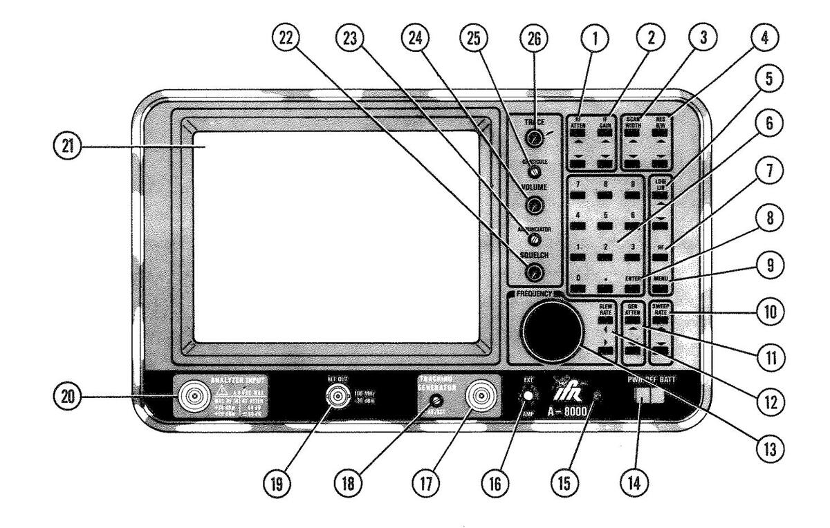
- 1. RF ATTEN Kevs
- 2. IF GAIN Keys
- 3. SCAN WIDTH Kevs
- 4. RES B/W Kevs
- 5. LOG/LIN Keys
- 6. Numeric Keyboard
- 7. RF Key
- 8. ENTER Key
- 9. MENU Kev
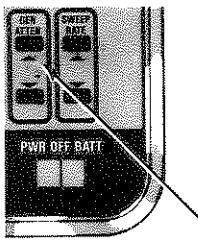
- 10. SWEEP RATE Keys
- 11. GEN ATTEN Kevs
- 12. SLEW RATE Keys
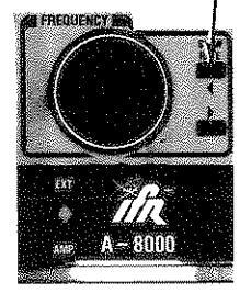
- 13. FREQUENCY Control
- 14. PWR/OFF/BATT Switch
- 15. Power On Indicator
- 16. EXT AMP Connector
- 17. TRACKING GENERATOR Connector 18. TRACKING ADJUST Control
- 19. REF OUT Connector
- 20. ANALYZER INPUT Connector
- 21. CRT Display
- 22. SQUELCH Control
- 23. ANNUNCIATOR Volume Adjust Control
- 24. VOLUME Control
- 25. GRATICULE Intensity Adjust Control
- 26. TRACE Intensity Control
Figure 3-1 A-8000 Front Panel Controls, Connectors and Indicators
3-1 FRONT PANEL
Refer to Figure 3-1 to locate the following on the Front Panel.
TTEM NAME DESCRIPTION
- 1. Keyboard keys and controls thru
- 13. See Paragraph 3-4 for descriptions of all keyboard keys and controls
NOTE
The Frequency Control is not a key; but as it performs a keyboard related function. it is described as one.
14. PWR/OFF/BATT Switch
Applies or interrupts electrical power as follows:
- PWR Position A-8000 is powered by AC or DC power source.
- OFF Position A-8000 is turned OFF.
- BATT Position A-8000 is powered by internal battery. if installed. Push once to apply battery power; push again to terminate battery operation. Plug into AC outlet to charge (see NOTE). The "BATT" position of the switch is spring loaded to the "OFF" position.
NOTE
A full charge requires at least 12 hours with a minimum external input of 15 VDC or 110 VAC.
15. Power On Indicator
Indicates A-8000 is turned on.
16. EXT AMP Connector
Provides power for optional External Amplifier.
17. TRACKING GENERATOR Connector
This is a Type-N Connector used for Tracking Generator Output. Impedance is normally 50Ω.
18. TRACKING ADJUST Control
Adjusts Tracking Generator frequency to match the Analyzer.
3-1 Blank/3-2
| ITEM | NAME | DESCRIPTION |
|---|---|---|
19. REF OUT Connector
Provides a 100 MHz signal at -30 dBm.
20. ANALYZER INPUT Connector
Input Connector for A-8000. Input impedance is normally 500.
21. CRT Display
Spectrum Analyzer display for A-8000. Refer to Paragraph 3-3 for details.
22. SQUELCH Control
Controls 10.7 MHz Receiver squelch threshold. Squelch disables demod audio output when RF input at ANALYZER INPUT Connector falls below squelch threshold. This control operates only when the 10.7 MHz Receiver is installed.
23. ANNUNCIATOR Volume Adjust Control
Controls volume of tone heard when a key is pressed. Adjust for comfortable listening level.
NOTE
As the annunciator tone is one of the indications of an "accepted" key entry, it is not advisable to turn the annunciator volume completely off.
24. VOLUME Control
Controls audio level to A-8000 speaker. This control operates only when the 10.7 MHz Receiver is installed.
25. Graticule Intensity Control
Adjusts brightness of displayed graticules. Adjust for desired contrast between displayed signals (trace) and graticules.
26. TRACE Intensity Adjust Control
Controls brightness of displayed signal field labels and menu.

| 27。 | DC Fuse | 33. | PEN LIFT Connector |
|---|---|---|---|
| 28. | DC Power Input Connector | 34. | Sweep Connector |
| 29. | AC Power Input Connector | 35. | Video Connector |
| 30. | AC Line Fuse | 36. | Not used |
| 31. | 10 MHz External Reference | 37. | GPIB or RS-232 Connector |
| Connector | (Option) | ||
| 32. | TCXO ADJ |
Figure 3-2 A-8000 Rear Panel
Refer to Figure 3-2 to locate the following on the Rear Panel of the A-8000.
| ITEM | NAME | D | ) | E | S | С | 1 | R | Ι | Р | T | Ī | ) |
|---|---|---|---|---|---|---|---|---|---|---|---|---|---|
27. DC Fuse
75 Amp. 32 VDC
28. DC Power Input Connector
12 to 30 VDC, nominal
29. AC Power Input Connector
Input connector for 106 to 266 VAC supply at 50 to 400 Hz.
30. AC Line Fuse
2½ amp, 250 V
31. 10 MHz External Reference Connector
Allows monitoring of internal 10 MHz reference frequency or application of external 10 MHz reference frequency (Time Base) at +5 dBm to +20 dBm. The input and output are switched automatically.
32. TCXO Adjust
Provides an adjustment point for the internal 10 MHz reference frequency (Time Base).
NOTE
Temperature of unit must be stabilized before adjusting the TCXO to ensure frequency accuracy.
33. PEN LIFT Connector
Allows for Pen Lift and Scope Blanking commands to be sent to a plotter. Signal is 0 to 4 VDC TTL.
34. SWEEP Connector
Provides an analog sweep output signal. May be connected to external equipment.
CAUTION
THIS PORT IS HIGH IMPEDANCE (O TO 5V RAMP OUTPUT, NOMINAL, INTO 1 MΩ). ANY DEVICE CONNECTED TO IT MUST HAVE A HIGH IMPEDANCE INPUT TO PREVENT DAMAGE TO THE UNIT.
35. VIDEO Connector
Provides a real-time analog video signal before trace display is digitized. May be connected to external equipment.
CAUTION
THIS PORT IS HIGH IMPEDANCE (O TO 800 mVDC OUT-PUT, NOMINAL, INTO 1 MΩ). ANY DEVICE CONNECTED TO IT MUST HAVE A HIGH IMPEDANCE INPUT TO PRE-VENT DAMAGE TO THE UNIT.
- 36. Not used
- 37. GPIB or RS-232 Connector (option)
Allows communication between A-8000 microprocessor and GPIB or RS-232 Interface.
3-3 CRT DISPLAY
The CRT display graphics are automatically updated by the A-8000 microprocessor and controlled either through keyboard entries or, if installed, by remote unit entries (i.e., units connected via GPIB or RS-232). The CRT Display graphics include the trace functions, dB level and graticules, blocks for analyzer settings and menu displays
3-3-1 CRT DISPLAY VALUES
Following are the functions displayed on the A-8000 CRT (see Figure 3-3) and the keyboard components which control their settings. The keyboard is described in Paragraph 3-4.
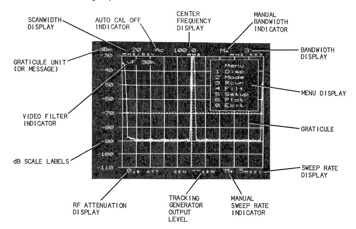
Figure 3-3 Interaction of CRT Display and Keyboard
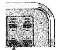
3-3-1-1 SCAN WIDTH DISPLAY
This displays the current Scan Width. It is changed when one of the Scan Width keys (up or down) is pressed. Changing the Center Frequency may also change the Scan Width display. See paragraphs 3-3-2 and 3-4-3.
3-3-1-2 CENTER FREQUENCY DISPLAY
This displays the current value of the Center Frequency. The number of significant digits displayed is determined, in part, by the Scan Width selection. The Center Frequency value changes if the following keys are pressed: RF, ENTER (with or without selection of a Center Frequency value), or if the Frequency Control (13) is rotated. See Paragraphs 3-4-6, 3-4-7, 3-4-11 and 3-4-12.
3-3-1-3 BANDWIDTH DISPLAY
This block displays the current Resolution Bandwidth setting. It changes when one of the RES B/W keys is pressed (see Paragraph 3-4-4). It may also change if one of the SCAN WIDTH keys is pressed or the Center Frequency is changed when Bandwidth Optimization is active (See Appendix E).
NOTE
During Quasi-Peak operation, the Quasi-Peak function controls the Bandwidth block. Quasi-Peak bandwidths are assigned automatically at each Quasi-Peak operational selection.
3-3-1-4 MENU DISPLAY
This display shows the active menu. The area within the rectangular box (and including the box) is called the menu window. This appears only when the menu function is active. See Paragraph 4-1 for details.
3-3-1-5 SWEEP RATE DISPLAY
This displays the current Sweep Rate. It changes when one of the Sweep Rate keys is pressed up or down (see Paragraph 3-4-9). This display may also change when one of the SCAN WIDTH keys or one of the RES B/W keys is pressed. The SCAN WIDTH and RES B/W keys or selecting a Video Filter affect the Sweep Rate display only if Sweep Rate Optimization is active (see Appendix E).
3-3-1-6 RF ATTENUATION DISPLAY
This displays the current level of RF Attenuation. It changes when one of the RF ATTEN keys is pressed up or down, within the 0 to 60 dB range of the A-8000. See Paragraph 3-4-1.
3-3-1-7 TRACKING GENERATOR OUTPUT DISPLAY
This displays the RF level at the Tracking Generator output. If the Tracking Generator is not installed, this display is inhibited from the CRT. When the Tracking Generator is active, the output level is controlled by the GEN ATTEN keys (see Paragraph 3-4-10). When the Tracking Generator is installed, but the Generator option is turned off (GEN = Ø in SETUP Menu), the display that appears is "GEN -- unit". The unit is always the same as the unit displayed above the graticule scale.
3-8
3-3-1-8 GRATICULES/dB SCALE LABELS
This shows the signal level and provides a numeric readout for the signal under observation. There are three settings for these labels: 10 dB increments/Division, 2 dB increments/Division and a Linear scale. The 10 dB/DIV and 2 dB/DIV scales provide a direct readout of the signal. The top graticule of the Linear scale shows the signal level with RF Attenuation and IF Gain. Computing the Signal Amplitude on the Linear Scale is discussed in Appendix C. Graticule scales are changed with the RF ATTEN keys, IF GAIN keys, LOG/LIN keys and in the SETUP Menu. See Paragraphs 3-4-1, 3-4-2, 3-4-5 and 4-7. The peak signal indicated by the graticule level is the ACTUAL Analyzer Input level of RF.
3-3-1-9 GRATICULE UNIT DISPLAY
This display shows the current calibration unit for the graticule scale labels. The unit can be changed in the SETUP Menu to display dBm, dBµW, dBV, dBmV or dBµV. Changing the units also changes the graticule readings as shown in Table 3-1. Table 3-1 shows the top graticule labels as different units are selected as they appear in the Menu. The RF Attenuation and IF Gain are kept constant. The difference between the readings in 50Ω operation and 75Ω operation are as they appear only if the impedance setting is changed.
| UNIT |
TOP
GRATICULE (Ø dB RF ATTEN, Ø dB IF GAIN) |
TOP
GRATICULE (3Ø dB RF ATTEN, Ø dB IF GAIN) |
|---|---|---|
| 50Ω 0 P | ERATION | |
|
d Bm
d BmV d BµV d BµV d BV d BµW |
- 30
+17 +77 -43 0 |
0
+47 +107 -13 +30 |
| 75Ω OP | ERATION | |
|
d Bm
d Bm V d Bµ, V d BV d BV d Bµ, W |
- 2 4
+ 2 5 + 8 5 - 3 5 + 6 |
+6
+55 +115 -5 +36 |
Table 3-1 A-8000 Units Comparison
The unit block may also display an error condition, if one is detected in the A-8000 Spectrum Analyzer. Paragraph 3-3-2 describes these conditions, and several other messages that are displayed on the A-8000.
3-3-2 SPECIAL DISPLAY MESSAGES AND INDICATORS
3-3-2-1 UNCAL MESSAGE
This message is displayed where the Graticule Unit normally appears. It indicates the A-8000 is not at an optimal setting (see Appendix E).
3-3-2-2 UNLOK MESSAGE
This message is displayed where the Graticule Unit normally appears. It indicates an improperly functioning frequency synthesizer, which requires calibration or some other maintenance.
3-3-2-3 AC INDICATOR (Ac)
This indicator is displayed if the Auto Cal feature is turned off. It is set in the MANUAL Menu (see Paragraph 4-9) and appears between the SCAN WIDTH and CENTER FREQUENCY displays on the top of the screen.
3-3-2-4 MANUAL BANDWIDTH INDICATOR (M→)
This indicator (M→) is displayed in the upper right-hand corner of the screen. The arrow points to the Bandwidth display. It indicates Bandwidth Optimization is inactive (see Appendix E). This indicator appears only if "Bw" in the MANUAL Menu is set to "M" (see Paragraph 4-9).
3-3-2-5 MANUAL SWEEP RATE INDICATOR (M→)
This indicator (M→) is displayed in the lower right-hand corner of the screen. The arrow points to the Sweep Rate display. It indicates Sweep Rate Optimization is inactive (see Appendix E). This indicator appears only if "Swp" in the MANUAL Menu is set to "M" (see Paragraph 4-9).
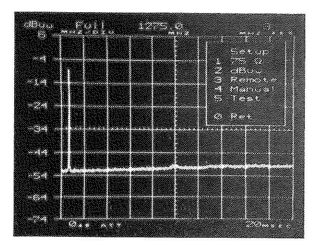
3-3-2-6 FULL SCAN INDICATOR (FULL)
This indicator is displayed when the "RF, ENTER" keys are pressed, and no Center Frequency value is selected. It indicates maximum Scan Width selection for the A-8000 Spectrum Analyzer (265 MHz/DIV). The Center Frequency is assigned a value of 1275.0 MHz. "FULL" appears instead of the Scan Width display and is replaced with a numeric value when the Scan Width or the Center Frequency changes.
3-3-2-7 VIDEO FILTER INDICATOR (vF 30K or vF 300)
The Video Filter Indicator is displayed only when one of the Video Filters (30 kHz or 300 Hz) is active. It appears in the upper-left quadrant of the CRT display. The indicator is set in the FILTERS Menu (see Paragraph 4-6).
3-4 KEYBOARD
Refer to Figure 3-3 to locate CRT displays and to Table 3-2 as a reference for entering key values. All keys on the A-8000 Spectrum Analyzer, except RF, ENTER, MENU and Numeric keys, are paired (up and down or left and right) for operator convenience.
Normally, when pressing a key on the keyboard, a tone is heard if an applicable change is made on the CRT display. However, on several of these keys (RF ATTEN, IF GAIN, SWEEP RATE and GEN ATTEN) the micro-processor disables the tone and inhibits the entry when attempting to enter an invalid value. If this happens, the operator may enter a valid setting.
When selecting a Center Frequency, if four digits are pressed after the decimal, the Center Frequency is entered automatically. Thus, it is not necessary to press the ENTER key in this situation. However, if less than four digits are entered after a decimal, the ENTER key must be pressed for the Center Frequency to be accepted.
| KEY(S) | USE | ENTRY METHOD | |||||
|---|---|---|---|---|---|---|---|
| RF ATTEN |
RF input atten from 0 to 60 dB in
10 dB steps |
RF ATTEN up or RF ATTEN down | |||||
| IF GAIN |
Internal IF gain from 0 to 65 dB in
1 dB steps |
IF GAIN up or IF GAIN down | |||||
| SCAN WIDTH |
Analyzer Display Scan Width from
1 kHz/DiV to 250 MHz/DIV; 0 for fixed-tuned receiver |
SCAN WIDTH up or SCAN WIDTH
down |
|||||
| SWEEP RATE |
Analyzer Display sweep rate from
5 mSec/DIV to 10 SEC/DIV |
SWEEP RATE up or SWEEP RATE
down |
|||||
| RES B/W |
Analyzer Bandwidth - 300 Hz, 3 kHz,
30 kHz, 300 kHz or 3 MHz |
RES B/W up or RES B/W down | |||||
| LOG/LIN |
Log - 10 dB or 2 dB per division on
vertical scale Lin - selects Linear display mode |
Press LOG/LIN up or LOG/LIN
down |
|||||
| RF | Enter center frequency setting |
RF XXXX.XXXX ENTER* or RF,
ENTER |
|||||
| MENU | Initiate/Terminate Menu display | Press MENU | |||||
| SLEW RATE | Center frequency digital slew setting |
Press LEFT or RIGHT to in-
crease or decrease significant digit being slewed. |
|||||
| FREQUENCY CONTROL | Slews Center Frequency |
Increases (cw) or Decreases
(ccw) Center Frequency. |
|||||
| GEN ATTEN |
RF output atten from 0 to -70 dBm
In 1 dB steps |
GEN ATTEN up or GEN ATTEN down | |||||
| NUMBERS | Center frequency entry and menu ops | Redefined by RF and MENU keys | |||||
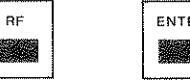
| ENTER |
Direct center frequency entry.
Returns FULL SCAN display to previous display selections. |
RF XXXX.XXX ENTER*; RF, ENTER
or ENTER (after RF, ENTER only). |
|||||
| *Values entered fo | *Values entered for RF entries can contain one to eight digits. The maximum length on either side of | ||||||
the drcimal point is shown here. The decimal is optional for integer values 0-2500 (2500 is the maximum acceptable RF entry). Entering an invalid value suppresses the beep tone. When entering less than four digits after the decimal point, the ENTER key must be pressed.
Table 3-2 A-8000 Keyboard Quick Reference
2.4.1 DE ATTEN KEVS (1)
FUNCTION: Set the attenuation of the RF signal input. RANGE: 0 to 60 dB, in 10 dB steps.
USE: RF ATTEN UP (A) causes attenuation to increase. RF ATTEN DOWN (4) causes attenuation to decrease. Using RF ATTEN with IF GAIN sets the top graticule of the CRT display as shown in Table 3-3. Generally, the RF ATTEN keys are used when the input signal level is greater than -30 dBm.
| RF ATTEN | IF GAIN | Top Graticule Reading |
|---|---|---|
| 0 | 0 | -30 |
| 10-60 | 0 | -20 to +30 |
| 0 | 1-65 | -31 to -95 |
| 10-60 | 1-65 | +29 to -85 |
Table 3-3 Interaction of RE ATTEN and IE GAIN
NOTE
The graticule readings are automatically changed if the Reference Scale Unit is changed (see Table 3-1)
NOTE
If a key is pressed and no beep is heard and (or) the display blocks do not change, then you have reached the end of the range of values. Check the range of values before selecting another entry.
3-4-2 IF GAIN KEYS (2)
FUNCTION: Set the internal IF gain level.
RANGE: 0 to 65 dB in 1 dB steps.
USE: IF GAIN UP (+) causes IF GAIN to increase. IF GAIN DOWN (+) causes IF GAIN to decrease. The signal level is read directly from the CRT display, regardless of the IF GAIN and RF ATTEN settings.
NOTE
If a key is pressed and no beep is heard and (or) the display blocks do not change, then you have reached the end of the range of values. Check the range of values before selecting another entry.
3-4-3 SCAN WIDTH KEYS (3)
FUNCTION: Set analyzer display Scan Width.
RANGE: 0, 1, 2, 5, 10, 20, 50, 100, 200 or 500 kHz/DIV; 1, 2, 5, 10, 20, 50, 100, 200 or 250 MHz/DIV.
USE: SCAN WIDTH UP (†) causes the Scan Width to increase until the maximum allowable Scan Width setting for the Center
Frequency setting is reached (see Table 3-4). If the SCAN WIDTH UP (†) key is pressed after the maximum allowable Scan Width value is displayed, the list cycles to the lowest Scan Width value (O Scan). The values then increase until the desired value appears in the Scan Width display (see Figure 3-3).
SCAN WIDTH DOWN (+) causes the Scan Width to decrease until the O Scan Width setting is reached. If the SCAN WIDTH DOWN key is pressed after the O Scan Width value is displayed, the Scan Width cycles to the maximum allowable Scan Width setting for the Center Frequency (CF) selection (see Table 3-4). The value then decreases until the desired value appears in the Scan Width display (see Figure 3-3).
Zero is selected for fixed-tune receiver operation. When selecting a Scan Width, the Resolution Bandwidth and Sweep Rate may change. This is the result of optimization; which is discussed in Appendix E. Also, the number of significant digits used for the Center Frequency may vary as the Scan Width increases or decreases.
| MAXIMUM SCAN WIDTH | CENTER FREQUENCY | ||
|---|---|---|---|
| SETTING (MHz/DIV) | RANGE (MHz) | ||
| 10 | 0.0 - 49.9999 | ||
| 20 | 50.0 - 199.9999 | ||
| 50 | 200.0 - 449.9999 | ||
| 100 | 450.0 - 949.9999 | ||
| 200 | 950.0 - 1199.9999 | ||
| 250 | 1200.0 - 1750.0 | ||
| 200 | 1750.0001 - 2000.0 | ||
| 100 | 2000.0001 - 2500.0 | ||
Table 3-4 Maximum Selectable Scan Widths at Allowable A-8000 CF Settings
For any Center Frequency selected, the microprocessor inhibits Scan Width settings which would display a signal less than -50 MHz or greater than +3000 MHz. For example, if the Scan Width is set at 100 MHz/DIV and the Center Frequency is set at 100.0 MHz, SCAN WIDTH will be reset to 20 MHz/DIV.
3_A_A RES RIW KEVS (A)
-
FUNCTION: Manually set bandwidth of analyzer trace (bandwidth can be automatically set by the microprocessor. but the RES B/W keys override the automatic selection). A detailed explana-tion of Resolution Bandwidth functions is the subject of Appendix D of this manual.
- RANGE . 300 Hz. 3 kHz. 30 kHz. 300 kHz or 3 MHz. Resolution Bandwidth can be automatically or manually selected for each bandwidth (see Appendix E and Paragraph 4-9). The UP key (1) changes the bandwidth selection in increasing order, the DOWN key (+) changes the bandwidth selection in decreasing order. If the Sweep Rate and Scan Width are too fast for the selected Resolution Bandwidth. "UNCAL" is displayed on the CRT instead of the graticule unit (see Figure 3-3).
NOTE
See Appendix D for a description of the Resolution Bandwidth function.
3-4-5 LOG/LIN KEYS (5)
- RANGE :
-
FUNCTION: Set the vertical scale of analyzer graticule display. 2 dB increments, 10 dB increments or, using the LIN scale, 18 dB for the top 87.5 percent of the screen (see Paragraph 8-2-2 and Appendix C for details on Linear Scale).
- 115F •
- Top graticule axis is set by selecting RF ATTEN and IF GAIN settings per Table 3-3. Intermediate horizontal graticules are not labeled in LINEAR mode. The UP (+) key cycles the vertical scale from 2 dB/DIV to 10 dB/DIV to LINEAR mode: the DOWN (*) key cycles the vertical scale from LINEAR mode to 10 dB/DIV to 2 dB/DIV.
10 dB and 2 dB sets all horizontal graticules in 10 dB or 2 dB increments. The top graticule corresponds with the RF ATTEN and IF GAIN settings per Table 3-3.
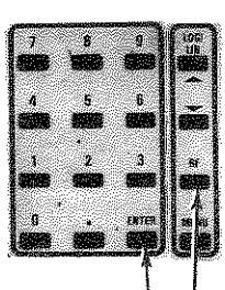
3-4-6 NUMERIC KEYS (6)
FUNCTION: Enter direct Center Frequency values or make menu selec-
of valid entries is from 0 to 2500,0000 (MHz).
USE: When used with the RF key, the numeric keys (and the decimal point) are used to select the Center Frequency. The range
When used during Menu operation the numeric keys are used to select menus and operating parameters, as described in Section 4.

Select and enter a Center Frequency entry.
If four digits are entered after the decimal the Center Frequency is entered automatically.
3-4-7 RF/ENTER KEYS (7/8)
FUNCTION: USE:
Where nnnn.nnnn is the value of the Center Frequency from Ø
Entry of Center Frequency is made using two selection methods: manual and automatic. To manually select a CF.
Where nnnn.nnnn is the value of the Center Frequency from Ø to 2500.Ø. If four digits are entered after the decimal, the Center Frequency is entered automatically.
To automatically set the Center Frequency to 1275.Ø MHz and the Scan Width to 265 MHz/DIV, press the following keys:
press the key sequence:
[NOTE]
When "RF ENTER" is entered, the message "FULL" is displayed in the SCAN WIDTH block, designating maximum Scan Width selection. This display remains until the Scan Width or the Center Frequency changes. When in FULL SCAN, the previous display and its parameters can be reset by pressing "ENTER". This feature operates in FULL SCAN only.

If a key is pressed and no beep is heard and (or) the display blocks do not change, then the entry is invalid. Check the range of values before selecting another entry.
3-4-8 MENU KEY (9)
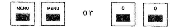
FUNCTION: USE: Turns menu display on or off. Pressing "MENU" causes the Master Menu to appear on the CRT. Pressing MENU a second time, clears any Menu display. Pressing MENU twice in succession when any other menu is displayed, causes the Master Menu to appear on the CRT (see Paragraph 4-1).
3-4-9 SWEEP RATE KEYS (10)
FUNCTION: Set Sweep Rate of analyzer display. RANGE: 5, 10, 20, 50, 100, 200, 500, mSec/DIV; 1, 2, 5 and 10 Sec/DIV.
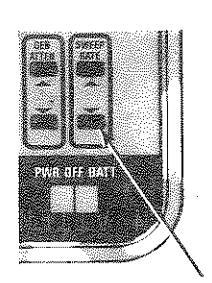
SWEEP RATE UP (T) causes sweep rate to increase (sweep time decreases). SWEEP RATE DOWN (*) causes sweep rate to decrease. Sweep Rates can be automatically selected via the Scan Width and RES B/W Keys or by selecting a video filter, but may be set independently to one of the sweep rates shown above (see Paragraph 4-9 and Appendix E). If the Sweep Rate selected for the Scan Width and Resolution Bandwidth is too fast, "UNCAL" is displayed on the CRT instead of the grati-cule unit (see Figure 3-3).
NOTE
If a key is pressed and no beep is heard and (or) the display blocks do not change, then you have reached the end of the range of values. Check the range of values before selecting another entry.
3-4-10 GEN ATTEN KEYS (11)
-
Set the output level if the Tracking Generator is installed and enabled.
- DANCE . 0 to -70 dBm in 1 dB steps.
GEN ATTEN UP (个) causes output level to increase. GEN ATTEN IISE : DOWN (*) causes output level to decrease.
NOTE
If a key is pressed and no beep is heard and (or) the display blocks do not change, then you have reached the end of the range of values. Check the range of values before selecting another entry.
3-4-11 SLEW RATE KEYS (12)
FUNCTION: Select the digit of the Center Frequency being slewed (see Figure 3-4).
RANGE ·
100 Hz digit to 1 GHz digit in increments of powers of 10. USE: Pressing either SLEW RATE key (RIGHT or LEFT) changes the Slew Rate by powers of 10. The Center Frequency digit to be slewed is displayed in reverse video as a non-blinking cursor. When either Slew Rate key is pressed. the digit where the cursor appears is relative to the current Scan Width selection. Pressing SLEW RATE LEFT (+) moves the cursor left, which results in changing the Slew Rate at larger increments. Pressing SIFW RATE RIGHT (+) moves the cursor right, which results in changing the Slew rate at smaller increments.
NOTE
These keys do not change the Center Frequency! This is the function of the Frequency Control (see Paragraph 3-4-12).
When using the Slew Rate keys (left or right). the cursor disappears when it is moved left of the 1 GHz digit or right of the 100 Hz digit.

Figure 3-4 Frequency Slew Digit Selection
3-4-12 FREOUENCY CONTROL (13)
-
FUNCTION: Increases or Decreases Center Frequency (CF). RANGE: O to 2500 MHz.
-
- USE: The Frequency Control (13) changes the CF at the selected slew rate setting (see Figure 3-4). If the slew rate cursor is not illuminated in the CF display. the Frequency Control changes the CF proportional to the Scan Width (i.e., Scan Width X 1).
-
NOTE
When changing the Center Frequency, the Scan Width may change (see Table 3-4 for maximum allowable Center Frequency settings).

Figure 3-5 Center Frequency Display With Slew Rate Cursor Illuminated
SECTION 4 - MENU OPERATION

NOTES:
The option not included, the "option not-installed" screen appears
> ONLY CURRENT SELECTION APPEARS IN MENU WINDOW
S> IF GEN OPTION NOT INSTALLED, THIS DISPLAY LINE IS INHIBITED
ONLY RS-232 OR GPIB MENU CAN BE DISPLAYED, DEPENDING ON OPTION INSTALLED. IF NEITHER OPTION IS INSTALLED, THE "OPTION NOT INSTALLED" SCREEN APPEARS
BODISPLAYS ONLY RESULT OF TEST (P OR F) FOR EACH TEST
UISPLATS UNLT RESULT OF LEST (P OR F) FOR EACH TEST VOLTAGE READING DISPLATED TO THE NEAREST .5 V INCREMENT, AT OR BELOW MEASURED VOLTAGE LEVEL. IF OPTION NOT INSTALLED, READING INDICATES BATTERY CIRCUIT CHARGE
T> RATE - 300/600/1200/2400/4800/9600/19200
B MODE - ODD / EVEN / NONE
9 DASHED LINE INDICATES OPTION
D> IF GPIB OPTION IS NOT INSTALLED, THIS DISPLAY IS INHIBITED
DIN "GPIB" AND "NENU" MENUS, EITHER PLOT OR PRINT APPEARS IN MENU WINDOW, EXCEPT AS NOTED IN DO
Figure 4-1 Menu Access in Menu Operation
4-1 Blank/4-2 01

4-1 MENUS
A-8000 operating parameters are set using direct entries from the keyboard: as described in Section 3 or via menu operation. Enter menu operation by pressing "MENU" on the keyboard. Menus can be subsequently cleared from the CRT display by pressing "MENU" a second time or by pressing "Ø" on the keyboard when the "Master" menu is displayed in the menu "window" (i.e., the area of the CRT display where the menu appears).
4-1-1 MENU LEVELS
A-8000 menus operate on multiple levels (see Figure 4-1). The Master Menu is the only first level menu. It is used to select a second level menu. The selections are listed in the menu window (DISP, MODE, RCVR, FILTERS, SETUP and, optionally, PLOT/PRINT). Select a second level menu by pressing the NUMBERED KEY corresponding with the number listed in the menu window left of the desired menu.
Two second level menus can be used to select third level menus. The FILTERS menu can be used to select the QUASI-PEAK menu. The SETUP menu can be used to select the REMOTE, MANUAL and TEST menus. Also, some menus can be selected only if a particular option is installed (QUASI-PEAK, RCVR or REMOTE). If one of these menus is selected and the option is not installed, the OPTION NOT INSTALLED menu appears in the menu window.
NOTE ]
The REMOTE menu displays either the RS-232 menu or the GPIB menu, when selected, if either option is installed.
Return to the previous menu level by pressing O (RETURN) on the keyboard. Pressing the MENU Key twice in succession during menu operation causes the Master Menu to appear in the menu window.
4-1-2 MENU OPERATION NOTES
- The figures in this section are to illustrate the various A-8000 MENUS. Parameter values and waveforms should be ignored in every instance -- unless specifically referred to in the text.
- 2. The key shown next to each paragraph is that key required to select the corresponding function in the menu.
4-2 MASTER MENU
To enter menu operation, press the MENU key once. All other menus on the A-8000 are directly or indirectly selected from the Master Menu.

a) Master Menu with GPIB

b) Master Menu Without GPIB
Figure 4-2 Master Menus
To select the CRT Display (DISP) Menu, press "1" on the keyboard. The DISP Menu is discussed in Paragraph 4-3. To return to the Master Menu, press "Ø" on the keyboard.

To select the Signal Display (MODE) Menu, press "2" on the keyboard. The MODE Menu is discussed in Paragraph 4-4. To return to the Master Menu, press "Ø" on the keyboard.

To select the Receiver Bandwidth (RCVR) Menu, press "3" on the keyboard. The RCVR Menu is discussed in Paragraph 4-5. If the 10.7 MHz Receiver is not installed in the A-8000, refer to Paragraph 4-12. To return to the Master Menu, press "Ø" on the keyboard.

To select the Video and Quasi-Peak FILTERS Menu, press "4" on the keyboard. The FILTERS Menu is discussed in Paragraph 4-6. To return to the Master Menu, press "Ø" on the keyboard.
To select the SETUP Menu, press "5" on the keyboard. The SETUP Menu is discussed in Paragraph 4-7. To return to the Master Menu, press "0" on the keyboard.
Refer to Paragraph 4-11 before selecting the PLOT/PRINT function. If the GPIB option is not installed in the A-8000 and this function is selected, the menu display is inhibited. To return to the Master menu, press "Ø".
4-3 DISPLAY (DISP) MENU
To select the Display (DISP) Menu, press "1" on the keyboard when the Master Menu appears in the menu window. To select a display function, the DISP Menu must appear in the menu window. The arrow in the menu window points to the current menu selection (e.g., "REF" in Figure 4-3).
Figure 4-3 DISPLAY (DISP) Menu
To select LINE display, press "1" on the keyboard. This causes the Analyzer Trace to be represented as a solid line.
To select BAR display, press "2" on the keyboard. This causes the Analyzer Trace to be represented as a shaded area on the CRT.
To select REF display, press "3" on the keyboard. The REF display shows a signal display which represents the difference between a live trace and a stored trace. (Live and Stored traces are discussed in Paragraph 4-4).
NOTE
When REF mode is selected, the entire display changes to display Ø dB as a reference at the center graticule (see Figure 4-3). Returning to LINE or BAR display mode returns the scale and unit to their previous settings.

returning to the Master Menu.

To return to the Master Menu, press "Ø" on the keyboard.
4-4 MODE MENU
To select the MODE Menu, press "2" on the keyboard when the Master Menu appears in the menu window. The MODE Menu must appear in the menu window before selecting a mode for signal display. The arrow in the menu window points to the current menu selection (e.g, "PkHold" in Figure 4-4).
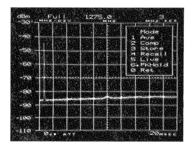
Figure 4-4 MODE Menu
To select AVE (Average) mode, press "1" on the keyboard. In this mode, the last three sweeps are averaged with the current sweep (i.e., four sweeps), which are continuously updated to reflect the average.

To select COMP (Compare) Mode, press "2" on the keyboard. The trace stored in memory is compared to and displayed with the current (live) trace. The shaded area is the difference between the live and stored traces. Selecting COMP automatically sets the DISPLAY Menu to BAR.

To select STORE Mode, press "3" on the keyboard. The current trace and display parameters are stored.
NOTE
When store is selected, the arrow in the menu window momentarily points to "3" and returns to the previous selection.

To select RECALL Mode, press "4" on the keyboard. The stored trace, with its parameters, are recalled and displayed on the CRT. Changing any parameter after selecting RECALL results in the A-8000 switching to LIVE Mode.
NOTE
Changing menu parameters when RECALL Mode is active may result in erroneous, even conflicting, CRT displays. Do not change menu parameters in RECALL Mode.

To select LIVE Mode, press "5" on the keyboard. This is the normal mode of operation.

To select PKHOLD (Peak Hold) Mode, press "6" on the keyboard. PKHOLD Mode continually stores and displays maximum signal amplitude. The difference between the current signal and the maximum signal is displayed as a shaded area.

) before returning
to the Master Menu.
Select LIVE mode (press

To return to the Master Menu, press "Ø" on the keyboard.
RCVR MFNII
To select the RCVR (Receiver) Menu, press "3" on the keyboard when the Master Menu appears in the menu window. The RCVR Menu only appears if the 10.7 MHz Receiver is installed in the A-8000. Otherwise, the OPTION NOT INSTALLED menu (see Paragraph 4-12) appears in the menu window when this menu is selected. The RCVR Menu must appears in the menu window before selecting a receiver option. The arrow in the menu window points to the current menu selection. (e.g., "FM1" in Figure 4-5 except the TSR selection).
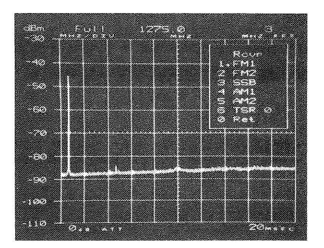
Figure 4-5 RCVR Menu
To select the FM1 (15 kHz narrow band) Receiver Bandwidth, press "1" on the keyboard.
To select the FM2 (200 kHz wide band) Receiver Bandwidth, press "2" on the keyboard.

To select the SSB (6 kHz Single Side Band) Receiver Bandwidth, press "3" on the keyboard.

To select the AM1 (6 kHz narrow band) Receiver Bandwidth. press "4" on the keyboard.

To select the AM2 (15 kHz wide band) Receiver Bandwidth, press "5" on the keyboard.
To select Time Share Reception ON (TSR = 1) or OFF (TSR = 0). press "6" on the keyboard. When TSR is on, the A-8000 sweeps the frequency spectrum for ONE FULL SWEEP; it then locks into Center Frequency for ONE FULL SECOND, to allow audio to be heard. The controller is then updated and another full sweep is taken, repeating the cycle. If TSR is inactive, zero scan width must be selected for fixed-tune operation. (See NOTE on next page.)
NOTE
During TSR operation, the speaker sounds increasingly disrupted as the sweep time becomes slower. Also, CERTAIN KEYS MAY APPEAR TO HAVE AN ACTION DELAY AS KEY ENTRIES ATTEMPTED DURING AUDIO RECEPTION ARE IGNORED (i.e., they are locked out by the controller).
NOTE
Set TSR to Ø. Then select the receiver bandwidth you wish to use for operation before returning to the Master Menu.

To return to the Master Menu, press "Ø" on the keyboard.
4-6 FILTERS MENU
To select the FILTERS Menu, press "4" on the keyboard when the Master Menu appears in the menu window. The FILTERS Menu must appear in the menu window to select a filter. The arrow in the menu window points to the current menu selection (e.g., 30K in Figure 4-6).
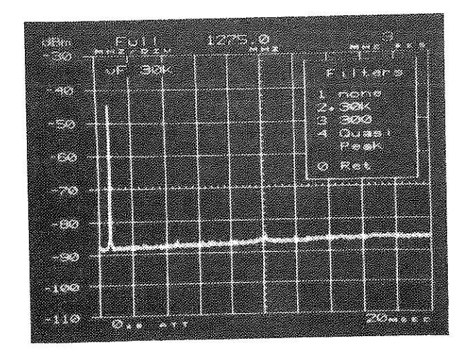
Figure 4-6 FILTERS Menu
4-6-1 VIDEO FILTER INDICATOR
If a video filter is selected, the selected filter value (30 kHz or 300 Hz) is displayed in the upper-left quadrant of the CRT screen (see Figure 4-6). If the filter display is on the screen, then the video filter is active.
4-6-2 FILTERS MENU SELECTIONS
To select NO FILTERING (NONE), press "1" on the keyboard.

To select the 30 kHz Video Filter, press "2" on the keyboard. When the 30 kHz Video Filter is selected, Sweep Rate Optimization may occur. Refer to Table E-4 for details.

To select the 300 Hz Video Filter, press "3" on the keyboard. When the 300 Hz Video Filter is selected, Sweep Rate Optimization may occur. Refer to Table E-3 for details.

The Quasi-Peak Menu, described in Paragraph 4-6-3, can only be selected when the Quasi-Peak option is installed.

returning to the Master Menu.
To return to the Master Menu, press "Ø" on the keyboard.
4-6-3 QUASI-PEAK FILTER MENU
To select the QUASI-PEAK Menu, press "4" on the keyboard when the FILTERS Menu appears in the menu window. The Quasi-Peak Menu appears only if the Quasi-Peak Detector is installed in the A-8000. Otherwise, the OPTION NOT INSTALLED menu appears in the menu window. The Quasi-Peak Menu must appear in the menu window before selecting a Quasi-Peak function (see Section 8 for full operation details). The arrow in the menu window points to the current menu selection (e.g., "TC3" in Figure 4-7).

Figure 4-7 QUASI-PEAK Menu
NOTE
When Ouasi-Peak is selected:
- The microprocessor automatically sets the video filter to "NONE" (i.e., no video filter).
- 2. Optimization occurs to conform the Resolution Bandwidth and Sweep Rate to the Time Constant selection. These settings remain until another FILTERS Menu selection is made.
- 3. When the Quasi-Peak Detector is turned off (i.e., another filter or no filter is selected), the Resolution Bandwidth is automatically reset to the next highest setting. For example, if TC1 is used during Quasi-Peak operation, when the Quasi-Peak Detector is turned off, the Resolution Bandwidth will be reset to 300 Hz.
To select TC1 (Time Constant 1), press "1" on the keyboard when the Quasi-Peak Menu appears in the menu window. TC1 provides the charge and discharge time required for Quasi-Peak measurements from 10 kHz to 150 kHz and sets the Resolution Bandwidth to 200 Hz.

To select TC2 (Time Constant 2), press "2" on the keyboard when the Quasi-Peak Menu appears in the menu window. TC2 provides the charge and discharge time required for Quasi-Peak measurements from 150 kHz to 30 MHz and sets the Resolution Bandwidth to 9 kHz.

To select TC3 (Time Constant 3), press "3" on the keyboard when the Quasi-Peak Menu appears in the menu window. TC3 provides the charge and discharge time required for Quasi-Peak measurements from 30 MHz to 1 GHz and sets the Resolution Bandwidth to 120 kHz.
To return to the FILTERS Menu, press "Ø" on the keyboard
and select "NONE" (press
4-7 SETUP MENU
To select the SETUP Menu, press "5" on the keyboard when the Master Menu appears in the menu window. The SETUP Menu must appear in the menu window before selecting SETUP functions (see Figure 4-8).


(b) SETUP Menu With Tracking Generator
Figure 4-8 SETUP Menus
Press "1" on the keyboard, to select 500 or 750 operation. The current impedance selection is displayed in the menu window (see Table 3-1). Set this parameter to 500 operation.
NOTE
Changing the menu setting does not change the impedance! A 50 to 75Ω adapter must be connected to the ANALYZER INPUT Connector (20) to operate the A-8000 at 75Ω. Also, if using a Tracking Generator, a second 50 to 75Ω adapter must be connected to the Tracking Generator Connector (17), for 75Ω operation.
4-12
To reset the graticule unit, press "2" on the keyboard. The following units are selectable on the A-8000: dBm, dBmV, dBuV, dBV or dBuW. The current setting is displayed in the menu window. See Table 3-1 for Graticule Label differences when changing the unit. Set this parameter to "dBm".
To select the REMOTE operating mode described in Paragraph 4-8, press "3" on the keyboard. If neither Remote Option is installed (i.e., GPIB or RS-232), the OPTION NOT INSTALLED Menu appears in the Menu Window (see Paragraph 4-12).

To select the MANUAL Menu described in Paragraph 4-9, press "4" on the keyboard.

To select the TEST Menu described in Paragraph 4-10, press "5" on the keyboard.
To set the Tracking Generator ON (Gen = 1) or OFF (Gen = Ø), press "6" on the keyboard. The Tracking Generator must be installed in the A-8000 for this selection to appear in the SETUP Menu window (see Figures 4-8(a) and 4-8(b)). The unit in the Tracking Generator display corresponds with the Unit
Display and the Menu Window display (as set in Item
NOTE
It is recommended to set the Tracking Generator OFF (GEN = 0), unless specific measurements are being made with it.
To return to the Master Menu, press "Ø" on the keyboard.
4-8 REMOTE MENU
To select the REMOTE Menu, press "3" on the keyboard when the SETUP Menu appears in the menu window. When REMOTE is selected, the menu appearing in the menu window depends on the option installed in the A-8000:
- The GPIB Menu appears when the GPIB option (Option 05) is installed (see Paragraph 4-8-1).
- The RS-232 Menu appears when the RS-232 option (Option 06) is installed (see Paragraph 4-8-2).
- The OPTION NOT INSTALLED Menu appears when neither the GPIB nor the RS-232 option is installed (see Paragraph 4-12).
4-8-1 GPIB MENU
The GPIB Menu appears when the REMOTE Menu is selected and the GPIB option is installed. The GPIB Menu must appear in the menu window before the GPIB Address can be set (see Figure 4-9). The GPIB Address used must match the address specified in the interfacing software.
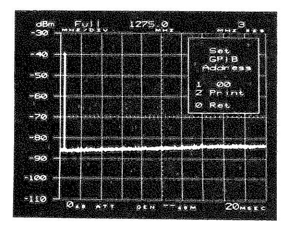
Figure 4-9 GPIB Menu
To select the GPIB Address, press "1" on the keyboard until the desired address appears in the menu window. The range of this address is from ØØ to 31 (decimal values).

To select the print or plot device, press "2" on the keyboard. Select Print if a Hewlett Packard ThinkJet" printer is connected to the A-8000; select Plot if a Hewlett Packard Graphics Language (HP-GL)" compatible plotter is connected to the A-8000. Item 6 in the Master Menu will reflect this selection. To return to the Master Menu, press:
NOTE
The device selected is stored in non-volatile RAM. Therefore, unless changing the device, it is not required to change this menu selection each time the A-8000 is powered on.

To return to the SETUP Menu, press "Ø" on the keyboard.
4-8-2 RS-232 MENU
The RS-232 Menu appears when the REMOTE Menu is selected and the RS-232 option is installed in the A-8000. The RS-232 Menu must appear in the menu window before RS-232 options can be set (see Figure 4-10).
NOTE
Refer to the COMMUNICATIONS Section of the external controller's manual before setting these parameters.
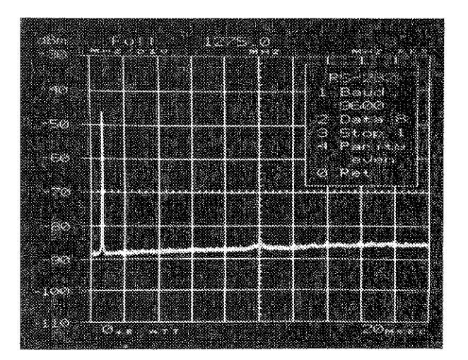
Figure 4-10 RS-232 Menu

To select the Baud Rate, press "1" on the keyboard until the desired Baud Rate appears in the menu window. The following Baud Rates are available on the A-8000: 300, 600, 1200, 2400, 4800, 9600 and 19200 baud. The current setting is displayed in the menu window.
To set the number of Data Bits per word, press "2" on the keyboard until the desired setting appears in the menu window. Data Bits can be set to 7 or 8. The current selection is displayed in the menu window.
To set the number of Stop Bits per word, press "3" on the keyboard until the desired setting appears in the menu window. Stop Bits can be set to 1 or 2. The current setting is displayed in the menu window.

To select the mode of Parity Check, press "4" on the keyboard until the desired mode appears in the menu window. Parity can be set to ODD, EVEN or NONE. The current setting is displayed in the menu window.
To return to the SETUP Menu, press "Ø" on the keyboard.
To select the MANUAL Menu, press "4" on the keyboard when the SETUP Menu appears in the menu window. The MANUAL Menu must appear in the menu window before MANUAL Menu parameters can be set (see Figure 4-11).
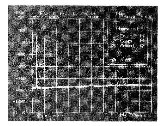
Figure 4-11 MANUAL Menu
NOTE!
A-8000 optimization is discussed in Appendix E.
- To turn Bandwidth Optimization ON (Bw = A) or OFF (Bw = M), press "1" on the keyboard. When Bandwidth Optimization is ON, the Resolution Bandwidth may change when the Center Frequency or Scan Width is changed. When Bandwidth Optimization is OFF, changing the Center Frequency or the Scan Width does not change the Resolution Bandwidth. "M+" is displayed next to the resolution bandwidth display when Bandwidth Optimization is turned OFF. Set Bw to A.
- To turn Sweep Rate Optimization ON (Swp = A) or OFF (Swp = M), press "2" on the keyboard. When Sweep Rate Optimization is ON, the Sweep Rate may change when the Center Frequency, Scan Width or Resolution Bandwidth is changed. When Sweep Rate optimization is OFF, changing the Center Frequency, the Scan Width or the Resolution Bandwidth does not change the Sweep Rate. "M+" is displayed next to the Sweep Rate display when Bandwidth Optimization is turned OFF. Set Swp to A.
- 3
To turn the Auto Cal function ON (Acal = 1) or OFF (Acal = Ø), press "3" on the keyboard. Setting Auto Cal OFF disables the Auto Cal feature, and displays "Ac" between the Scan Width and Center Frequency display blocks across the top of the CRT display. Returning to the ON state forces one Auto Cal cycle. Set Acal to 1.

To return to the SETUP Menu, press "Ø" on the keyboard.
4-10 TEST MENU
To select the TEST Menu, press "5" on the keyboard when the SETUP Menu appears in the menu window. When selected, all tests are automatically run. Once the tests are completed, any test can be rerun by pressing the number on the keyboard corresponding with the number of the desired test in the menu window. A passed test is indicated by "P" displayed to the right of the test in the menu window. A failed test is indicated by "F" displayed in reverse video to the right of the test in the menu window (e.g., see "RF" in Figure 4-12).
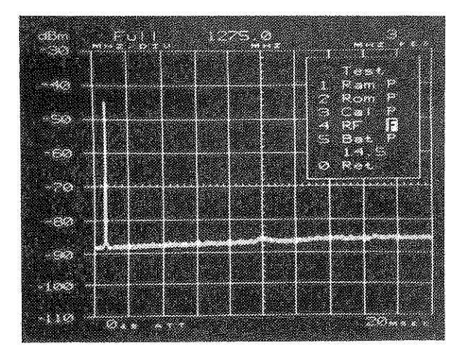
Figure 4-12 TEST Menu
To rerun the RAM test only, press "1" on the keyboard. This tests system RAM, CRT alpha RAM, and the Dual-port RAM. If all RAM tests pass, "P" is displayed in the menu window next to the RAM test. If any of the tests fail, they are indicated in reverse video as follows:
F1 - System RAM on Control Processor Board failure; F2 - CRT alpha RAM on Video Processor Board failure; F3 - Dual-port RAM on Video Processor Board failure.

To rerun the ROM test only, press "2" on the keyboard. This performs a checksum test on the system firmware.
To rerun the CAL test only, press "3" on the keyboard. This tests the Auto Cal subsystem.

To rerun the RF test only, press "4" on the keyboard. This tests the microprocessor communication between the RF Interface and all PC Boards. Phase lock condition is indicated by "P"; otherwise, the test fails.
To rerun the BATT test only, press "5" on the keyboard. This checks the battery charge level and displays the voltage in 0.5 V intervals (rounded down) of the measured voltage. If below +12 V, a failure condition is indicated
NOTE
When the battery test is performed and the battery is not installed, a voltage reading of the Battery Charge Circuit is taken. The battery test should pass and the reading should be 14.5 V.

To return to the SETUP Menu, press "Ø" on the keyboard.
4-11 PLOT/PRINT MENUS
NOTE
The Plot and Print Menus can be used only if the GPIB option is installed in the A-8000; otherwise, this menu item is inhibited.
4-11-1 PLOTTER/PRINTER INSTALLATION
The following steps are preliminary to using the A-8000 stored trace for plotting or printing:
- 1. Disconnect any GPIB Controller to the A-8000.
- 2. Connect a GPIB Cable between the GPIB Connector (37) on the Rear Panel of the A-8000 and the GPIB Connector of the device.
-
3. a. If plotting, the plotter must be compatible for use with Hewlett Packard Graphics Language (HP-GL)." Set the plotter to LISTEN ONLY mode.
- b. A Hewlett Packard ThinkJet™ printer must be used as the printing device. Set the printer to LISTEN ALWAYS mode.
- 4. Set the GPIB Menu (see Paragraph 4-8-1) to match item 6 of the Master Menu with the device.
NOTE
Item 6 of the Master Menu must match the device. Otherwise, the actions of the device will be unpredictable.
4 - 18 01
4-11-2 PLOTTER OPERATION
The Plot function plots a graph of a stored trace. To store a trace and plot it:
1. Select the MODE Menu. If the menu function is active, press:

If the Menu function is inactive, press:
2. Store the trace to be plotted. Press
3. Select the Plot Menu. Press
4. Select Plotter functions per Paragraph 4-11-3.
NOTE
Be sure the plotter is set up with pen(s) and paper before engaging the plotter function.
During plotter operation, the arrow in the menu window points to the active task (see Figure 4-13a). The arrow disappears when the task completes (see Figure 4-13b).
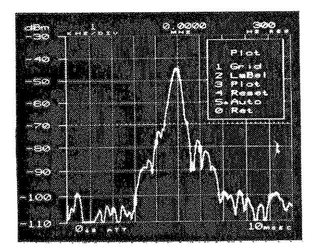

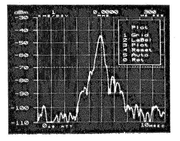
(b) Plot Menu When Waiting for Activity
Figure 4-13 PLOT Menus
When using a single pen plotter, if more than one color is desired for the plot, the stylus must be changed manually between plotter functions. In this case, use menu functions 1, 2 and 3 during plotter operation. If only one color is desired for the entire plot, menu function 5 (Auto) may be used for uninterrupted plotter operation.
When using a multiple pen plotter:
- Pen 1 is used to draw the trace only:
- Pen 2 is used to draw the grid, parameter labels and values;
- Pens 1 and 2 MUST be inserted for proper plotter operation:
- The Auto menu function (menu function "5") may be used for uninterrupted operation.
4-11-3 PLOT MENU FUNCTIONS
To draw the grid on the plotter, press "1" on the keyboard. This grid represents all graticules and tick markings of the A-8000.

To draw labels and parameter values of the stored trace, press "2" on the keyboard.

To draw the stored trace on the plotter, press "3" on the keyboard.

To stop any of the above functions before completion, press "4" on the keyboard. If the function is subsequently rerun, the plotter begins to draw at the starting position of the selected function.
The Auto selection performs the functions of selections 1, 2 and 3 without interruption. Press "5" on the keyboard to select "auto" operation.

To return to the Master Menu, press "Ø" on the keyboard.
4-11-4 PRINTER OPERATION
The Print function prints a graph of a stored trace. To store a trace and print it:
Select the MODE Menu. If the menu function is active, press: MENU 2 If the menu function is inactive, press: MENU 2 Store the trace to be plotted. Press: 3 Select the Print Menu. Press: 6 Select the Printer function. Press: 1
During printer operation, the arrow in the menu window points to the active task (see Figure 4-14a). The arrow disappears when the task completes (see Figure 4-14b).
NOTE
The printer ejects a page before it begins printing. The printer operates for approximately two and one-half minutes, until it completes the task.
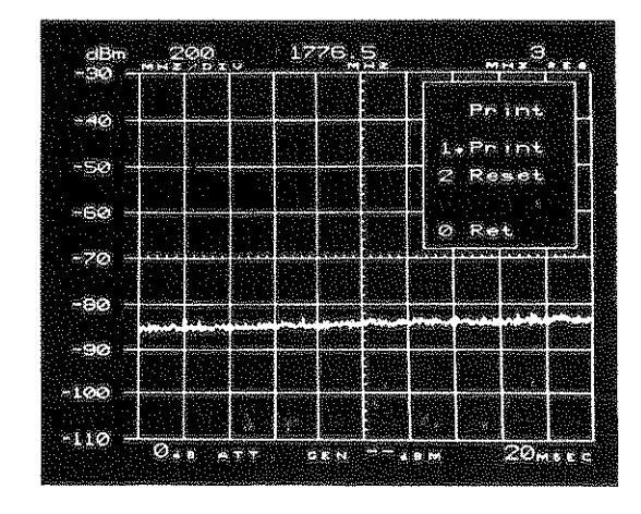
(a) Print Menu During Printer Activity

(b) Print Menu When Waiting for Activity

4-11-5 PRINTER MENU FUNCTIONS

Press "1" on the keyboard to print the stored trace directly on the printer.

Press "2" on the keyboard to stop the print operation while it is in progress. The print operation may then be restarted, if desired, by pressing "1".

Press "O" to return to the Master Menu when printing is completed.
4-12 OPTION NOT INSTALLED MENU
OPTION NOT INSTALLED is a message menu that appears when a selected option is not installed in the A-8000. For example, if the RCVR Menu is selected and the 10.7 MHz Receiver is not in the unit, OPTION NOT INSTALLED will be displayed in the menu window (see Figure 4-15).
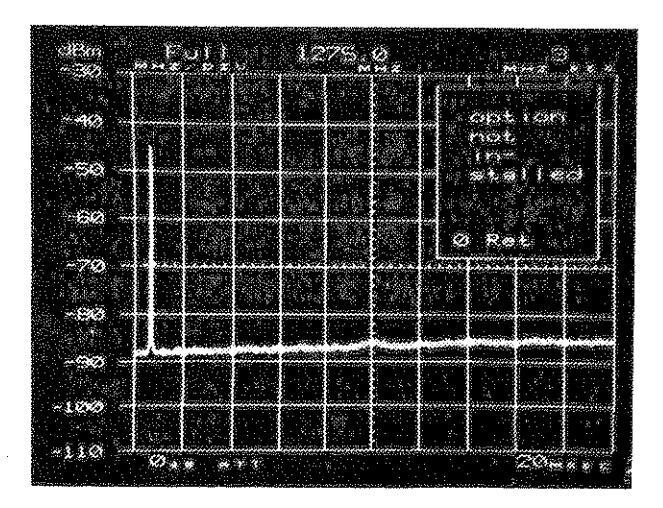
Figure 4-15 OPTION NOT INSTALLED Menu

Press "Ø" on the keyboard to return to the previous menu.
SPI.IIIIN 3 - KASH. IIPPKATHIN PKIILPHINPS
5-1 GENERAL
This section contains procedures to familiarize the user with the control papel on the A-8000 Spectrum Analyzer. The procedures cover a standard A-8000 Spectrum Analyzer and operation for the 750 10 7 MHz Receiver and Tracking Generator options. None of the procedures require internal access to the unit. Throughout the procedures. numbers in narentheses refer to the Front and Rear Panels (Figs. 3-1 and 3-2). T + may also be necessary to refer to Figures 3-3 (CRT display) and 4-1 (Menu displays) until the user is familiar with the unit.
Several procedures are included in this manual for GPIB (Section 6). RS-232 (Section 7) and Quasi-Peak Filter (Section 8) operation. Refer to the appropriate section(s) of this manual to use any of these procedures.
OPERATING NOTES.
ANNUNCIATOR
Beeps only if key entry is valid and is accepted by the microprocessor. Volume is controlled by the ANNUNCIATOR Volume Adjust (23). (VOLUME Control (24) is for demod audio and applies only to the 10.7 MHz Receiver option.)
NUMERIC/ENTER KEYS Numeric Keys (6) are used to enter a Center Frequency or select a Menu function. ENTER (8) must be pressed. unless entering a Center Frequency with four decimal places right of the decimal point.
FULL SCAN
Pressing "RF, ENTER" (7) (8) sets the Center Frequency to 1275.0 MHz and the Scan Width to 265 MHz/DIV. 265 MHz/DIV is designated as "FULL" in the Scan Width Block on the CRT display (21). Pressing "ENTER" after FULL SCAN is selected changes back to the previously selected parameters.
GRATICULE LABELS
The microprocessor changes the graticule labels based on RF attenuation, IF Gain, Impedance or Graticule Unit selection (see Paragraph 3-3-1). In all cases, the level of an input signal is the actual level displayed on the CRT.
5-2 A-8000 OPERATION PROCEDURES
5-2-1 PROCEDURE FOR STANDARD A-8000 UNIT
STEP ACTION
- Connect AC Power Cord to AC Power Connector (29) and Plug into electrical outlet.
- Set PWR/OFF/BATT Switch (14) to "PWR".
- Wait approximately ten seconds or press any key.
- 4. If necessary, adjust TRACE Intensity Control (25) and GRATICULE Intensity (24).

RESULT/NOTE
Outlet must meet requirements stated in Paragraph A-5.
Power On Indicator (15) should light up and the IFR logo should appear on the CRT display (21).
The IFR logo should disappear, replaced by the graticule display.
Sets CRT display to desired contrast. Use a small nonmagnetic screwdriver or a tuning tool for the GRATICULE Intensity Adjust.
Verifies Master Menu appears on CRT display.
Verifies SETUP Menu appears on the the CRT display.
Verifies TEST Menu appears on CRT display and all tests Pass (i.e., "P" is indicated in menu window following each test).
NOTE
Individual tests can be run by pressing the numeric key equivalent of the test in the menu window.
Returns to SETUP Menu.
Alternates graticule display between 50Ω and 75Ω settings. Select 50Ω.
NOTE
Selecting 75Ω impedance only changes the setting and graticule scales. If operating at 75Ω, a 75Ω adapter must be connected to the ANALYZER INPUT Connector (20).
8. Press:

9. Press:

стер
10. Press:
11. Press:
ACTION
12. Press:

13. Press:
| 14. | Press: |
|---|---|

15. Press:
RESULT/NOTE
Verifies MANUAL Menu appears on CRT display.
Alternates between Bandwidth Optimization and Manual Bandwidth selection. When optimization is active, Bw = A is displayed in the menu window. When optimization is inactive, Bw = M is displayed in the menu window and the Manual Bandwidth Indicator (M+) appears on the CRT Display. Set menu to indicate Bandwidth Optimization is active. The Manual Indicator should disappear.
Alternates between Sweep Rate Optimization and Manual Sweep Rate selection. When optimization is active, Swp = A is displayed in the menu window. When optimization is inactive, Swp = M is displayed in the menu window and the Manual Bandwidth Indicator (M+) appears on the CRT Display. Set menu to indicate Sweep Rate Optimization is active. The Manual Indicator should disappear.
Alternates between Auto Calibration (Auto Cal) active or inactive. When Auto Cal is active, Acal = 1 is displayed in the menu window. When Auto Cal is inactive, Acal = 0 is displayed in the menu window and the Auto Cal Indicator (Ac) appears in the CRT Display. Set menu to indicate Auto Cal is active. The Auto Cal Indicator should disappear.
Menu should disappear and reappear with Master Menu in menu window.
Verifies DISPLAY Menu appears.
Selects LINE mode of operation.
Returns to Master Menu.
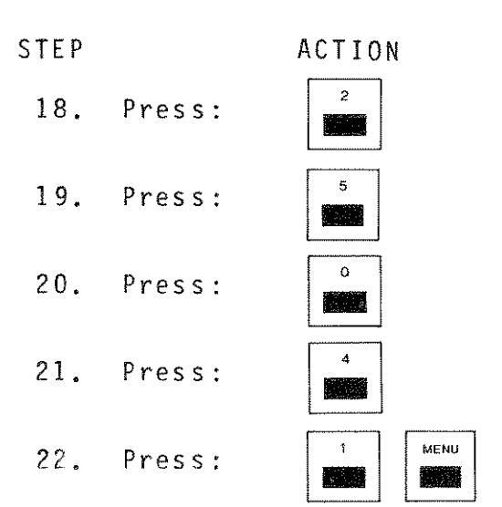
RESULT/NOTE
Selects MODE Menu.
Selects LIVE mode of operation.
Returns to Master Menu.
Selects FILTERS Menu.
Selects NO FILTER option, then clear the Menu display.
23. Press the following key sequences as needed:
| ENTER | ||
|---|---|---|
| (a) er | ENTER |
Sets Center Frequency to 100.00 MHz.
NOTE
Only significant digits appear in the Center Frequency display. Significant digits are determined, in part, by Scan Width.
Sets RF ATTEN to 10 dB. Press RF ATTEN key (up or down) until the desired level appears in the RF ATTENUATION display block on the CRT display.
Sets Scan Width to 1 MHz/DIV. Press one of the Scan Width keys until 1 MHz/DIV appears in the Scan Width display block on the CRT display.
Sets Graticule Scale to 10 dB/DIV. Press one of the LOG/LIN keys until the graticules at each major division are 10 dB apart.
Steps down IF GAIN. Continue to step down the IF GAIN until top graticule reads -20 dBm.
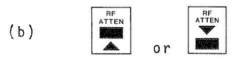
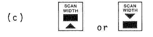


STEP ACTION
RESULT/NOTE
24. Connect 50Ω Type-N-to-BNC Coax Cable from REF OUT (19) to ANALYZER INPUT (20).
CRT display should be similar to Figure 5-1.
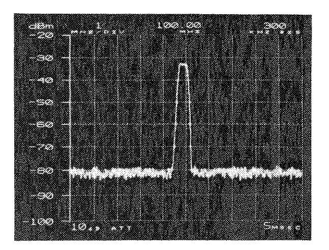
Figure 5-1 REF OUT Signal Display
Steps up IF GAIN in 1 dB steps. Continue to step up IF GAIN 10 dB and watch the entire display, including the noise floor, move up with each step.
Steps down IF GAIN in 1 dB steps. Continue to step down IF GAIN 10 dB and watch the entire display, including the noise floor, drop with each step.
Steps up the RF Attenuation 10 dB. The noise floor does not change, but the graticule display changes.
Selects FULL Scan. The Center Frequency setting is 1275.0 MHz.
The cursor should appear at the 100 MHz digit of the Center Frequency display.

30 With the cursor lit, rotate the FREQUENCY Control cw.

31. Press:

and rotate the FREQUENCY Control ccw.

32. Press:
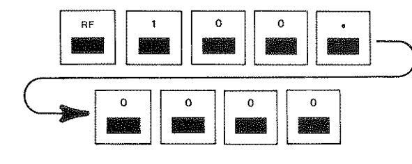
33.
Press
The CRT display changes as the SCAN WIDTH decreases. The shape of the signal changes relative to the Resolution Bandwidth vs. the Scan Width (see Appendix D). Scan Width should step down to 0 kHz/DIV.
Resets Scan Width to 10 kHz/DIV.
1. The Center Frequency increases in multiples of 100 MHz.
DECHLT/NOTE
- 2. The "FULL" indicator is immediately replaced by the 250 MHz/DIV Scan Width setting.
- 3. The Center Frequency cannot be incremented to a value greater than 2500 MHz
- 4. If attempting to scan frequen-cies greater than 3000 MHz, the Scan Width automatically changes (see Table 3-4).
- 1. The Center Frequency now decreases relative to the Scan Width setting (.1 X Scan Width).
- 2. The Center Frequency cannot be decremented to a value less than 0 Hz
- 3. If attempting to "scan" frequencies less than -50 MHz. the Scan Width automatically changes (see Table 3-4).
Resets the Center Frequency to 100 MHz. (The ENTER Key (8) function is performed automatically.)
until the cursor disappears
STED
34.
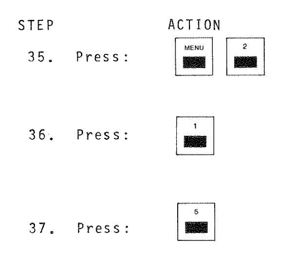
RESULT/NOTE
Re-enters Menu mode and selects MODE Menu.
Selects AVERAGE mode of operation. The noise level in the display should be reduced.
Returns to LIVE operation mode.
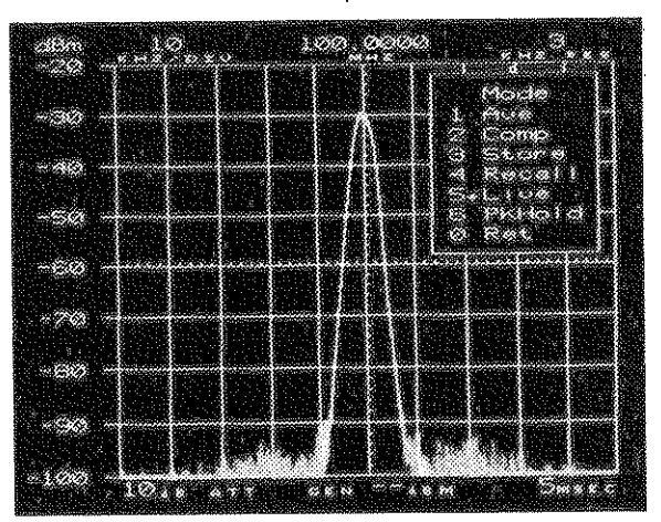
Figure 5-2 Live Trace to be Stored
Stores the display in memory.

When "3" is pressed, the arrow in the menu momentarily points to "3" and returns to the previous mode of operation.
Selects RECALL mode to observe the stored display. Display should be similar to Figure 5-2.
NOTE
The parameters from the STORED trace are displayed ONLY in RECALL mode.

39. Press:
4
STEP
40 Press.
40. Press:
41. Press:
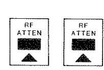
ACTION
RESULT/NOTE
Returns to LIVE operation mode.
Adds 20 dB RF Attenuation to signal. This increases the level of RF ATTEN to 30 dB and drops the signal amplitude on the CRT display 2 major divisions (compare Figure 5-2 to Figure 5-3).
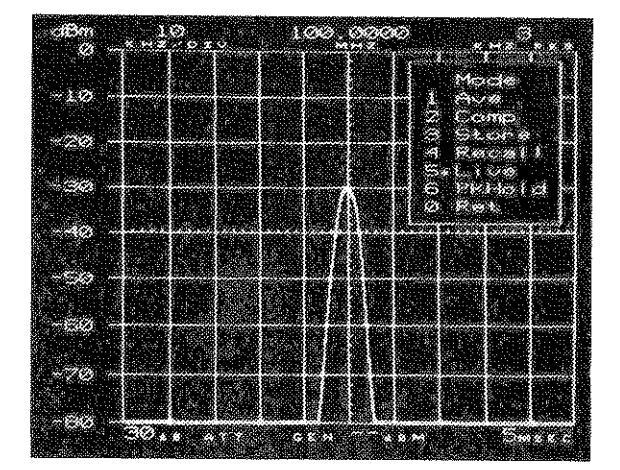
Figure 5-3 Signal with 30 dB RF ATTEN
Selects COMPARE operation mode. The shaded area on the CRT display represents the difference between the stored (Figure 5-2) signal and the LIVE (Figure 5-3) signal (i.e., 20 dB amplitude difference with same RF).
NOTE
In compare mode, only the current parameters (LIVE) are displayed on the CRT display.
42. Press:

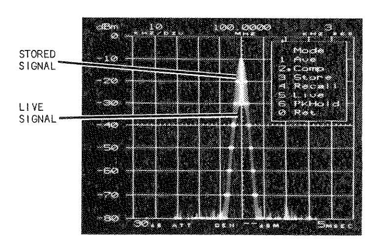
Figure 5-4 COMPARE Mode Display: STORED vs. LIVE TRACE
Returns to Master Menu and selects DISP (Display) Menu.
Selects REF (Reference) Mode. In REF mode, the stored trace becomes the reference and is displayed as 0 dB (Center Graticule) on the CRT display. The difference between the STORED (0 dB reference) and the current (LIVE) trace results in the signal displayed in Figure 5-5.
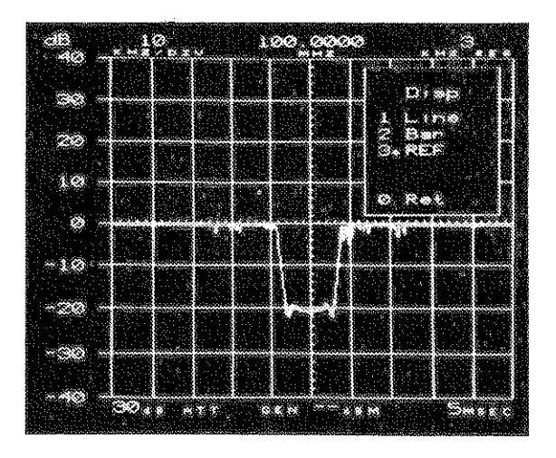
Figure 5-5 REF Mode Display (20 dB ATTEN Difference)
43. Press: 44. Press: 3
STEP
ACTION
45. Press:
RESULT/NOTE
Sets RF ATTEN to 10 dB. The signal should now be represented, basically, as a straight line, as in Figure 5-6. This display shows equal amplitude and frequency.
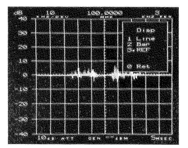
Figure 5-6 REF Mode Signal Display
Returns to Master Menu, selects MODE Menu and sets it to LIVE Mode.
47. Press:
Clears the Menu display from the CRT display.
END OF TEST
46. Press:
5-2-2 75Ω OPERATION PROCEDURE
NOTE
This procedure can only be used if the optional 50 to 750 Adapter is available for your unit. The procedure requires a Signal Generator with 750 output impedance.
| STEP | ACTION | RESULT/NOTE | |
|---|---|---|---|
| 1. |
Connect 75Ω adapter(s) to
ANALYZER INPUT Connector (20). |
Enables A-8000 to operate at 75Ω impedance. | |
| 2. | Press: |
Enters Menu Mode and selects 75Ω
operation in the SETUP Menu. |
|
| 3. | Press: |
Selects "dBm" for the Graticule
Scale. |
|
| 4. | Press 4 | Selects the MANUAL Menu. | |
| × | 5. | Press: |
Sets Bandwidth Optimization to
AUTOMATIC (Bw = A) |
| 6. | Press: |
Sets Sweep Rate Optimization to
AUTOMATIC (Swp = A). |
|
| 7. | Press: |
Sets Auto Cal feature ON (ACal =
1). |
|
| 8. | Press: |
Returns to the Master Menu and
selects the LINE display in the DISP Menu. |
|
| 9. | Press: | Returns to the Master Menu and selects the LIVE mode in the MODE menu. | |
| 10. | Press: | Returns to the Master Menu and selects NONE in the FILTERS Menu. | |
| 11. | Press: RF nnnn.nnnn ENTER |
Sets the Center Frequency to RF
Frequency of 75Ω Source. |
|
| 12. | Press: | Sets RF Attenuation to 10 dB. | |
| 13. | Set the Signal Generator as follows: |
a. RF Frequency = Same as in Step 11. b. MODULATION = NONE c. RF LEVEL = -30 dBm
| Т | ΕP | Аст | TON |
|---|---|---|---|
| ⊢ 1 | TON |
- 14. Connect 75Ω coax cable between The generated signal should Signal Generator and 50 to measure -30 dBm. 75Ω adapter on A-8000.
- Disconnect the Signal Generator and 75Ω Adapter.
- 16. Press:
Resets Graticule Scale and operational settings for 50Ω operation.
Clears menu display from CRT.
END OF TEST
17. Press:

NOTE
This procedure can only be used if the 10.7 MHz Receiver is installed in your A-8000 Spectrum Analyzer. If the RCVR menu is selected and the 10.7 MHz Receiver is not installed, the "OPTION NOT INSTALLED" Menu will be displayed in the menu window. Press "O" to return to the Master Menu.
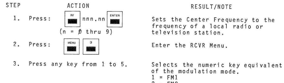
- 2 = FM2 3 = SSB
- 3 = SSB 4 = AM1
- 4 = AM1 5 = AM2
RESULT/NOTE
ACTION
4 Press:
Sets Scan Width to O kHz/DIV for fixed tune operation.
NOTE
When the set-up is complete, use the following procedure to test the 10.7 MHz FM/AM Receiver operation.
CAUTION
DISCHARGE YOUR ANTENNA BEFORE CONNECTING IT TO THE ANALYZER INPUT. STATIC DISCHARGE CAN CAUSE SERIOUS DAMAGE TO THE A-8000.
- 5. Connect antenna to ANALYZER INPUT Connector (20).
- Vary SQUELCH (22) and VOLUME (24) Controls.
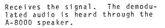
Verifies the Squelch Control squelches audio reception and the Volume Control increases and decreases speaker volume level.
Sets Time Share Reception (TSR) to ON position (TSR = 1).
Increases Scan Width and listens to demodulated audio.
NOTE
During TSR operation, the speaker sounds increasingly disrupted as the sweep time becomes slower. Also, CERTAIN KEYS MAY APPEAR TO HAVE AN ACTION DELAY AS KEY ENTRIES ATTEMPTED DURING AUDIO RECEPTION ARE IGNORED (i.e., they are locked out by the controller).
Turns TSR OFF (TSR = Ø) and clears the Menu from the CRT display.


END OF TEST
STEP
NOTE
This procedure can only be performed if the Tracking Generator is installed in your A-8000 Spectrum Analyzer.

6. Connect TRACKING GENERATOR (17) to ANALYZER INPUT (20).


RESULT/NOTE
Turns the Tracking Generator ON (GEN 1).
Sets Tracking Generator level. Repeat until tracking level is -35
Sets the Center Frequency to 100.0000 MHz.
Sets RF Attenuation to 10 dB.
Clears the menu display.
Uses 500 Type-N to Type-N coax cable.
Decreases Scan Width. Repeat until Scan Width is set to 10 kHz/DIV.
Sets Resolution Bandwidth. Repeat until Resolution Bandwidth is 3 kHz. Verify CRT display is as shown in Figure 5-7.

Figure 5-7 Tracking Generator Display

END OF TEST
RESULT/NOTE
Adjusts display for maximum signal amplitude.
Sets Graticule Scale to 2 dB/DIV.
Decreases Generator Output 1 dB. Repeat until Generator Output level decreases 10 dB. The CRT display should change at each 1 dB step.
Re-enters Master Menu and selects SETUP Menu.
Turns off Tracking Generator.
Clears menu display.

SECTION OF BEID OF ENATION
6-1 REMOTE (GPIB) OPERATION
Remote communication with the A-8000 is available by using the General Purpose Interface Bus (GPIB). This option conforms to IEEE Standard 488-1978. The test set conforms with the following IEEE Subsets: SH1, AH1, T6, TE0, LA, LE0, SR1, RL2, PP0, DC1, DT1 and C0. These subsets allow the A-8000 to perform the following functions:
Complete Source and Acceptor Handshake Talker with Serial Poll Listener Service Request Remote/local (No local lockout capability)
Device Clear
The GPIB Address is set in the GPIB Menu (see Paragraph 4-8-1).
All communication with the A-8000 through the GPIB requires ASCII encoded character strings. Invalid or improperly formatted characters are discarded and cause an error status bit to be set. Exceptions to this are the IEEE 488-1978 BUS Messages defined in Table 6-2. These messages require immediate attention from the A-8000 to continue processing character strings. The commands are stored in a 128-byte buffer until one of the following messages is received: Carriage Return, Line Feed, Null Character, "END" or "IDY". All commands are then run and measurements made or initiated.
All A-8000 responses returned across IEEE 488-1978 channels are ASCII encoded character strings ending with both CARRIAGE RETURN and LINE FEED commands. (Some controllers may ignore one of these commands.) The EOI message is imparted with the LINE FEED Command.
NOTE
Some command responses (e.g., MODE=STORE: GET(XX)?) have longer than average controller response times. This is expected, and the input time-out parameters for IEEE 488-1978 Controllers should be set to at least thirty seconds.
PLOTTER ADDRESS = 31
6-1-1 PREPARATION FOR USING GPIB
When the GPIB option is installed, a 24-pin connector is provided on the rear panel for connecting the A-8000 to an external controller (see Figure 6-1).


GPIB Connector pinouts are defined in Table 6-1.
| Pin No. | Signal | Pin No. | Signal |
|---|---|---|---|
| 1 | DIO 1 | 13 | DIO 5 |
| 2 | DIO 2 | 14 | DIO 6 |
| 3 | DIO 3 | 15 | DIO 7 |
| 4 | DIO 4 | 16 | DIO 8 |
| 5 | EOI | 17 | REN |
| 6 | DAV | 18 | Ground |
| 7 | NRD | 19 | Ground |
| 8 | NDAC | 20 | Ground |
| 9 | IFC | 21 | Ground |
| 10 | SRQ | 22 | Ground |
| 11 | ATN | 23 | Ground |
| 12 | Ground | 24 | Ground |
Table 6-1 Pinout for GPIB Connector
Once the proper connection is made, the A-8000 can be initialized with the proper address using the GPIB Menu. Refer to Paragraph 4-8-1 for the GPIB Menu instructions.
|
M N E M O N I C
M E S S A G E |
ASCII CODE (HEX) |
IEEE 488-1978
INSTRUCTION DEFINITION (SEE NOTE) |
| ATN | bus signal line | ATTENTION |
| DAB | 00-7F | Data Byte |
| DAC | bus signal line | Data Accepted |
| DAV | bus signal line | Data Valid |
| DCL | 14 | Device Clear |
| END or EOI | bus signal line | End |
| GET | 08 | Group execute trigger |
| GTL | 01 | Go to Local |
| IDY | bus signal line | Identify |
| IFC | bus signal line | Interface clear |
| LLO | 11 | Local Lockout |
| MLA | 20-3F | My listen address |
| МТА | 40-5F | My talk address |
| REN | bus signal line | Remote enable |
| RFD | bus signal line | Ready for data |
| SPD | 19 | Serial poll disable |
| SPE | 18 | Serial poll enable |
| SRQ | bus signal line | Service Request |
| STB | 00-FF | Status Byte |
| UNL | 3 F | Unlisten |
| UNT | 5 F | Untalk |
Table 6-2 IEEE 488-1978 BUS Messages
NOTE
Refer to the IEEE Standard 488-1978 for full definitions.
6-1-2 A-8000 AND GPIB MESSAGE INTERFACE
Following are A-8000 responses to external controller requests during remote communication. Table 6-2 defines each of the mnemonic messages.
- ATN The A-8000 GPIB I/O device responds immediately to process the incoming GPIB controller commands.
- DAB The A-8000 microprocessor responds by status testing of the GPIB I/O device to accept the data byte.
- DAC The A-8000 GPIB I/O device responds immediately to signal the talker that it has accepted the data byte.
- DAV The A-8000 GPIB I/O device responds immediately to signal the interceptor that it has put valid data on the BUS.
- DCL The A-8000 processor responds to reset the test set to its initialized state.
- END or The A-8000 responds to terminate the command input from the EOI source and begin processing the commands available up to the last valid delimiter.
- GET The A-8000 responds to terminate any further inputs and executes the commands available up to the last available delimiter.
- GTL The A-8000 processor responds to remove itself from control over the test set, therefore returning control to the front panel.
- IDY Same as "END" or "EOI".
- IFC The A-8000 processor responds by returning to local mode.
- LLO No response to this message.
- MLA The A-8000 GPIB I/O device responds immediately by comparing its address with the given listen address. If the two are the same, it instructs the processor to listen.
- MTA The A-8000 GPIB I/O device compares its address with the talk address given. If the two are the same, it instructs the processor to talk.
- REN The A-8000 processor responds from the interface to put the test set into remote, which disables front panel operation.
- RFD The A-8000 GPIB I/O device signals the source that it is ready for data to be transmitted on the bus.
- SPD The A-8000 GPIB I/O device terminates the service request operation by disabling the serial poll.
6 - 4
- SPE The A-8000 GPIB I/O device places the status byte on the BUS addressed to talk.
- SRQ The A-8000 processor instructs the interface to signal the controller that servicing is desired. (This is done under A-8000 software control.)
- STB The A-8000 GPIB I/O device responds immediately after the SPE and MTA messages by placing the status byte on the BUS.
- UNL The A-8000 GPIB I/O device and the processor respond to unlisten the test set.
- UNT The A-8000 GPIB I/O device and the processor respond to untalk the test set.
- 6-1-3 GPIB TRANSACTIONS
Following are examples of GPIB transactions showing the ASCII Character String to be transmitted and the corresponding BUS operations required to complete the communication. These examples were generated and run using a GPIB controller with a BASIC Interpreter. Enhancements to the controller allowed direct communication across the GPIB using special GPIB interface hardware.
In the examples, Step 1 shows the transmitted ASCII character string. Step 2 shows the bus operations required to complete the transaction.
-
A. Example No. 1 Instruct the A-8000 to set the RF to 500 MHz.
- ASCII String: "RFF = 500" (Followed by carriage return and line feed.)
- 2. BUS Transaction: UNT, UNL, MTA, DAB "R", DAB "F", DAB "F", DAB "=", DAB "5", DAB "0", DAB "0", DAB CR, DAB LF.
-
B. Example No. 2 Instruct the A-8000 to return the RF Attenuation which is -10 dB.
- 1. ASCII String: "RFATN?"
-
2. BUS Transaction:
- a. Output Cycle UNT, UNL, MLA, MTA, DAB "R", DAB "F", DAB "A", DAB "T", DAB "N", DAB "?", DAB CR, DAB LF.
- b. Input Cycle UNT, UNL, MLA, MTA, DAB "1", DAB "0", DAB CR, DAB LF.
6 - 5
6-1-4 STATUS AND SERVICE REQUEST TRANSACTIONS
The A-8000 has the capability to trigger a service request, based on one to six trigger conditions which can be set by the user with the "SRQ=" command. After the A-8000 is connected to the controller, it may be interrogated for the one byte status information. If an internal error or status condition becomes true and the matching trigger bit of the SRQ trigger byte (bits 0 through 5) has been set, bit 6 is also set. Bit 6 is generally used as the service request bit, signaling the GPIB controller that the A-8000 desires servicing. For definitions of how status bits are set, see Table 6-3.
|
STATUS
BIT NO. |
STATE | DEFINITION |
|---|---|---|
| 0 | 0000001 | RAM Error |
| 1 | 0000010 | ROM Error |
| 2 | 00000100 | Autocal test failure |
| 3 | 00001000 | RF test failure |
| 4 | 00010000 | To be defined |
| 5 | 00100000 |
A-8000 recognizes remote
state |
| 6 | 0100000 | Service Request Bit |
| 7 | 1000000 | ERROR - a command error has occurred |
Table 6-3 Status Bit Definition
6-2 COMMAND AND DATA STRUCTURE
All A-8000 functional commands and data information are transferred over the GPIB as uppercase ASCII Alphanumeric Character Strings and are designed to replace the front panel controls.
6-2-1 GPIB COMMANDS TO THE A-8000
All commands sent to the A-8000 are placed in an internal queue that can accommodate up to 128 bytes of data. Command Strings may be packed together, but the individual commands must be separated by delimiters. The delimiters are:
ASCII COLON ":" or some other assigned ASCII character ASCII PERIOD "." ASCII QUESTION MARK "?"
NOTE
The Question Mark ("?") is accepted at any time, but it is ignored unless it follows a command. This allows the user to continually interrogate the output buffer when waiting for a measurement. Do not use the Question Mark as a general delimiter.
The Period (".") can be used at any time, but is ignored unless used with the designated commands or as a decimal. Avoid using the period as a general delimiter.
The general delimiter is assigned using the DEL= Command. This can be any valid ASCII character with a decimal equivalent of 0 to 127 (e.g., comma (",") = 44, colon (":") = 58 and semicolon (";") = 59.
To avoid confusion or ambiguity, certain characters should not be assigned as delimiters. These include the period, question mark and all numeric and alphabetic characters.
The following ASCII Characters terminate the output command or series of commands:
Carriage Return (OD) - CR Line Feed (OA) - LF NULL Character (O) - NL
When the A-8000 is assigned talker, the EOI line is set when line feed (OA) is sent.
NOTE
The external GPIB controller must be programmed to expect an ASCII line feed (OA) character as the termination character of the input string.
6-2-2 GPIB COMMAND DATA FORMAT
All spaces are ignored by the controller. Following are some valid command examples:
SWEEPR = 100: SWEEPR? SCANW? RFATN = 10
NOTE
One of the following line terminators should be included at the end of every line to prevent execution errors from occurring: CR, LF, NL or EOI.
Maximum command string length, including spaces and delimiters, is 128 characters. If the command string exceeds this length, only those commands prior to the last delimiter and preceding the 128th character are performed. Commands past that delimiter are truncated and the Error Status bit ("7") is then set. Commands ending with an ASCII Question Mark ("?") normally require the user to enter an ASCII String Input Command after issuing an output command.
EXAMPLE:
COMMAND: RFF?SCANW?RID=ON:RFATN? RESPONSE: 500:100:RFATN = 10
These commands set the Reply Identifier Flag which causes the command label following "RID=ON" to be attached to the response.
6-2-3 RETURN DATA FORMAT
The returned data format convention is similar to the Output Command Data Format in that all returns are packed and separated by the assigned general delimiter(s) and must end with CARRIAGE RETURN and LINE FEED Commands. The number of responses returned is determined by the number of commands transferred in one block. If the number of responses required causes the internal response buffer to overflow, because it exceeds 128 characters, then only those characters up to the last delimiter before the 128th character are returned.
Input data that is out of range generally defaults to the minimum value(s) or the initialized value(s).
Figure 6-2 shows a reconstructed output produced by an IEEE 488-1978 controller. The requested parameters are listed to the right of the output sample.
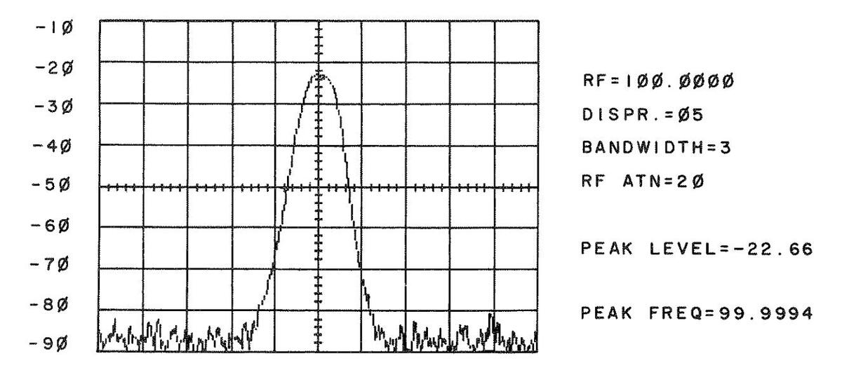
Figure 6-2 IEEE 488-1978 Display Output
6-8
6-2-4 REPLY IDENTIFIER
When the Reply Identifier is activated by the command "RID=ON", the returned information for data or status requests are preceded by the command mnemonic and an "=" character. This continues until the command "RID=OFF" is issued or the A-8000 power is cycled. This feature is especially useful for identifying measured data returned after a time delay, or from a string of commands.
6-3 A-8000 COMMAND SET
Table 6-4 defines, in alphabetic order, the ASCII Commands used to control the A-8000 under GPIB operation. Delimiters for each command are used throughout the Table to define different command types:
"=" represents a "set value to" operation for that command. "?" represents a "get value" operation for that command. "." represents an "enable" operation.
Items listed under the range column reflect data entered into or retrieved from the A-8000. Data shown in parentheses is data retrieved from the unit. Data not enclosed in parentheses is data being sent to the A-8000. A series of dashes means that the command is imperative (no data required as input or output).
NOTE
All commands and data entries must be numeric, one of the assigned delimiters, or an alphabetic (UPPERCASE or lowercase) character.
NOTE
When entering values for "BW=" or "SCANW=" commands, trailing zeroes right of a decimal will NOT be accepted (e.g.: BW=3.[OK]; SCANW=.03 [OK]; BW=3.0 [REJECTED]; SCANW=.3000 [REJECTED]).
| COMMAND | DANCE | |
|---|---|---|
| COULT WD | KANGE | DEFINITION |
| ACAL | ~ |
Forces one AutoCal cycle,
if AutoCal enabled. |
| ACAL = | 0,1 |
Disables (Ø) or Enables
(1) Auto Cal feature. |
| ACAL? | (0,1) |
Returns A Cal status
(Enabled or Disabled) |
| BATT? | (11.0 to 15.0 V, 0.5 V steps) | Returns Battery voltage. |
| B W = | .3,3,30,300,3000 kHz | Sets Resolution B/W |
| BW? | (.3,3,30,300,3000 kHz) | Gets Resolution B/W |
| BWC = | A or M |
Disables (M) or Enables
(A) B/W optimization. |
| BWC? | (A or M) | Returns B/W optimization status. |
| DEL = | 0 to 127, inclusive. |
Sets the delimiter to the
ASCII character repre- sented by the assigned decimal number. |
| DEL? | (0 to 127) |
Returns the decimal
number for the ASCII delimiter character. |
| DISP= | LINE, BAR, REF | Sets display to one of three modes. |
| DISP? | (LINE, BAR, REF) |
Returns display mode of
A-8000. |
| G E N = | 1,0 | Sets the generator on (1) or off (Ø). |
| GEN? | (1,0) |
Returns status of Gen
Switch. |
| GENLVL = | 0 to 70 |
Sets generator output
level. Depends upon "REF=" and "IMPD=" Command settings. |
Table 6-4 A-8000 Instruction Set
NOTE
Range must be entered in numeric or alphabetic (UPPERCASE or lowercase) characters.
6-10
| COMMAND | RANGE | DEFINITION |
|---|---|---|
| GENLVL? | (0 to 70) |
Returns generator output
level setting. |
| GET(xx)? | (0 to 511) |
Returns 10 points out of
the 390 stored points from the last stored display beginning with data group xx (1-39). The returned points are separated by the de- limiter assigned in the DEL= command (see Note 2). |
| IFGAIN= | 0 to 65, step 1 dB | Sets the IF GAIN to the designated value. |
| IF GA IN? | (0 to 65) | Gets the IF GAIN value. |
| IMPD= | 50,75 | Sets the impedance (in ohms). |
| IMPD? | (50,75) | Gets the impedance value. |
|
MIN?
MIN(from)? MIN(from:to)? |
(0-511:1-390) |
Returns the minimum value
of the last stored display for the specified horizontal range. The value is returned in the format: (yyy:xxx); where yyy is the minimum level (0 to 511) corresponding to the requested hori- zontal value(s) (1 to 390). The range returned can be in the following formats: |
NOTE
- Range must be entered in numeric or alphabetic (UPPERCASE or lowercase) characters.
- 2. When receiving display data points, values not displayed can be returned. When receiving a STORED REF trace, values can be negative or greater than 511, as this is a computed RATIO (i.e., (stored signal)/(input signal)).
6-11
| COMMAND | RANGE | DEFINITION |
|---|---|---|
| MIN? (cont.) |
MIN? - The entire
stored display is scanned for the minimum signal level. MIN(from)? - The stored display is scanned from the specified hori- zontal value to the end of the display. MIN(from:to) - The stored display is scanned from the first speci- fied point to the second specified point. |
|
| [NOTE] | ||
|
These points must be spe-
cified in proper sequence (that is, minimum value must be less than or equal to maximum value). The delimiter separating "from:to" and returned requests is assigned with the DEL= command. If no value precedes the de- limiter, 1 is assumed to be the first assigned point. |
||
| MODE = |
AVE,COMP,STORE,RECALL,LIVE,
PKHOLD |
Sets A-8000 to selected mode. |
| MODE? |
(AVE,COMP,STORE,RECALL,LIVE,
PKHOLD) |
Returns A-8000 mode. |
NOTE
Range must be entered in numeric or alphabetic (UPPERCASE or lowercase) characters.
| COMMAND | RANGE | DEFINITION |
|---|---|---|
|
CUMMAND
PEAK? PEAK(from)? PEAK(from:to)? |
RANGE
(0-511:1-390) |
Returns the peak value of
the last stored display for the specified hori- zontal range. The value is returned in the for- mat: (yyy:xxx); where yyy is the maximum level (Ø to 511) corresponding to the requested horizon- tal value(s) (1 to 390). The range returned can be in the following formats: PEAK? - The entire stored display is scanned for the maximum signal level. PEAK(from)? - The stored display is scanned from the specified hori- zontal value to |
|
the end of the
display. PEAK(from:to) - The stored display is scanned from the first specified point to the second specified point. |
||
| NOTE | ||
|
These points must be
specified in proper se- quence (that is, minimum value must be less than or equal to maximum value). |
||
| Та | able 6-4 (Continued) A-8000 I | nstruction Set |
| NOTE |
Range must be entered in numeric or alphabetic (UPPERCASE or lowercase) characters.
| COMMAND | RANGE | DEFINITION |
|---|---|---|
| NOTE | ||
|
The delimiter separating
"from:to" and returned requests is assigned with the DEL= command. If no value precedes the de- limiter, 1 is assumed to be the assigned point. |
||
| PEAKF= | NONE, 30K, 300 | Sets peak filter value. |
| PEAKF? | (NONE, 30K, 300) | Gets peak filter value. |
| PUT(xx)= | 0-511 |
Sends 10 points to the
A-8000 to be stored for display beginning with data group xx (1-39). The data must be valid numbers separated by the delimiter assigned with the DEL= command. To display the transferred information, the A-8000 must be in the "recall" mode. |
| QUASI= | ТС1,ТС2,ТС3 |
Sets Quasi-Peak filter
value. |
| QUASI? | (TC1,TC2,TC3) |
Returns Quasi-Peak filter
value. |
| RCVR= | FM1,FM2,SSB,AM1,AM2 |
Sets 10.7 MHz Receiver
Modulation. |
| RCVR? | (FM1,FM2,SSB,AM1,AM2) |
Returns 10.7 MHz Receiver
Modulation. |
| REF = | DBM, DBUW, DBV, DBMV, or DBUV |
Sets scale reference
label. |
| REF? | (DBM, DBUW, DBV, DBMV, or DBUV) |
Returns scale reference
label. |
| RFATN= | 0 to 60, step 10 dB |
Sets RF Input Attenuator
level. |
NOTE
Range must be entered in numeric or alphabetic (UPPERCASE or lowercase) characters.
6-14
| COMMAND | RANGE | DEFINITION |
|---|---|---|
| RFATN? | (0 to 60, step 10 dB) |
Gets RF Input Attenuation
level. |
| RFF= | 0000.0000 to 2500.0000 | Sets Analyzer Frequency. |
| RFF? | (0000.0000 to 2500.0000) |
Returns Analyzer
Frequency. |
| RID= | ON/OFF |
Controls the Reply Ident-
ifier Switch. When ON, adds the command name followed by "=" as a pre- fix to a command's response. |
| RID? | (ON/OFF) | Returns the current reply identifier status. |
| SCALE= | 2, 10, LIN | Sets Amplitude Scale |
| SCALE? | (2,10,LIN) | Gets Amplitude Scale |
| SCANW= |
O; .001 to 250 MHz/DIV
(see Note 2). |
Sets Frequency scan range. |
| SCANW? | (0; .001 to 250 MHz/DIV) | Gets Frequency scan range. |
| SRQ= | 0X000000 to 1X111111 |
Sets the GPIB line inter-
rupt mask. An SRQ inter- rupt occurs for each set error or status con- dition. These conditions are: |
NOTE
- Range must be entered in numeric or alphabetic (UPPERCASE or lowercase) characters.
- See Paragraph 3-4-3 for details on valid scanwidth entries.
| COMMAND | RANGE | DEFINITION |
|---|---|---|
| BIT/SSTATECONDITION01RAM Error11ROM Error21Auto Cal21Auto Cal41RF test51Acknowledge61SRQ bit71Commanderror1 | ||
| SRQ? | (0X000000 to 1X111111) |
Returns the current
status of SRQ (see Bit(s), State, Condition in SRQ= Command. |
| SWEEPR= |
5 to 10000 MS/DIV in 1-2-5
steps (see Note 2). |
Sets Sweep Rate. |
| SWEEPR? |
(5 to 10000 MS/DIV in 1-2-5
steps.) |
Gets Sweep Rate. |
| SWPC= | A or M |
Disables (M) or Enables
(A) Standard Sweep rate Optimization. |
| SWPC? | (A or M) |
Returns Sweep rate
Optimization Status. |
| TEST |
Runs all A-8000
diagnostics and returns errors through the serial poll or SRQ? Command. |
|
| TOP? | (110 to -30) |
Returns top of screen
scale value. This enhances plotting the spectrum via a host com- puter. |
| T SR = | 1,Ø |
Sets Time Share Reception
(TSR) ON (1) or OFF (Ø). |
NOTE
Range must be entered in numeric or alphabetic (UPPERCASE or lowercase) characters.
6-16
| COMMAND | RANGE | DEFINITION |
|---|---|---|
| T SR ? | (1,Ø) |
Gets Status of Time Share
Reception. |
| VER? | (x.xx) |
Returns the current ver-
sion of the firmware in the A-8000. |
SECTION / - KS-Z3Z UPERATION
7-1 REMOTE CONTROL (RS-232) OPERATION
Remote communication with the A-8000 is provided by a half-duplex RS-232 type bus. An external controller configured to RS-232 operation is required. The A-8000 becomes a slave to the external controller.
7-1-1 PREPARATION FOR USING RS-232
A 25-pin connector is included on the rear panel, if the A-8000 is to be used for RS-232 communication to an external controller. Figure 7-1 shows the RS-232 connector used with the A-8000.
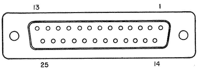
Figure 7-1 RS-232 Interface Connector
The operator must ensure proper interface between the A-8000 and the external controller. Table 7-1 shows the proper pinout for the RS-232 connector.
|
Pin No
(Note 1) |
Control Line |
Direction (relative
to A-8000) (Note 2) |
|---|---|---|
| 1.7 | GROUND | |
| 2 | TRANSMIT (TX) DATA | (Output) |
| 3 | RECEIVE (RX) DATA | (Input) |
| 4 | RTS | (Output) |
| 5 | CTS | (Input) |
| 6 | D S R | (Input) |
| 8 | DCD | (Input) |
| 20 | DTR | (Output) |
Table 7-1 RS-232 Connector Pinout
NOTE
- 1. Pin Numbers not listed are not used.
- Refer to Communications Section of Controller Manual for proper pin number connection of Controller.
- 3. CTS, DSR and DCD are connected on the interface board with optional jumpers. Some controllers require CTS to be isolated from DSR and DCD. DSR and DCD must be pulled up to enable A-8000 reception.
When the proper connection is made, use the MANUAL Menu on the A-8000 to set the RS-232 communications parameters (it should have the RS-232 option installed). See Paragraph 4-8-2 for parameter descriptions.
7-2 COMMAND AND DATA STRUCTURE
All A-8000 functional commands and data information are transferred over the RS-232 as uppercase ASCII Alphanumeric Character Strings and are designed to replace the front panel controls.
7-2-1 RS-232 COMMANDS TO THE A-8000
All commands sent to the A-8000 are placed in an internal queue that can accommodate up to 128 bytes of data. Command Strings may be packed together, but the individual commands must be separated by delimiters. The delimiters are:
ASCII COLON ":" or some other assigned ASCII character
ASCII PERIOD "."
ASCII QUESTION MARK "?"
NOTE
The Question Mark ("?") is accepted at any time, but it is ignored unless it follows a command. This allows the user to continually interrogate the output buffer when waiting for a measurement. Do not use the Question Mark as a general delimiter.
The Period (".") can be used at any time, but is ignored unless used with the designated commands or as a decimal. Avoid using the period as a general delimiter.
The general delimiter is assigned using the DEL= Command. This can be any valid ASCII character with a decimal equivalent of 0 to 127 (e.g., comma (",") = 44, colon (":") = 58 and semicolon (";") = 59.
To avoid confusion or ambiguity, certain characters should not be assigned as delimiters. These include the period, question mark and all numeric and alphabetic characters.


 Loading...