

MICROWAVE TEST SET 6200B SERIES
6200B 10 MHz to 20 GHz 6201B 10 MHz to 8 GHz 6202B 10 MHz to 2 GHz 6203B 10 MHz to 26.5 GHz 6204B 10 MHz to 46 GHz
© IFR Ltd. 1998
No part of this book may be reproduced or transmitted in any form or by any means, electronic or mechanical, including photocopying, or recorded by any information storage or retrieval system, without permission in writing by IFR Ltd.
IFR Ltd was formerly known as Marconi Instruments Ltd. Any reference in this manual to Marconi Instruments or MI should be construed as IFR Ltd.
Printed in the UK
Manual part no. 46882-240W Issue 4
17 November 1998
CONTENTS
Preface
Precautions
- Chapter 1 TECHNICAL DESCRIPTION
- Chapter 2 MAINTENANCE
- Chapter 3 ADJUSTMENT & CALIBRATION
- Chapter 4 INITIAL REPAIR
- Chapter 5 FAULT DIAGNOSIS
- Chapter 6 REPLACEABLE PARTS
- Chapter 7 SERVICING DIAGRAMS
Preface
CONVENTIONS
The following conventions apply throughout this manual:
| CAPS | Capitals are used to identify names of controls and panel markings, or system functions where no direct reference to an associated key is intended. |
|---|---|
| [CAPS] | Capitals in square brackets indicate hard key titles. |
| [Italics] | Italics in square brackets indicate soft key titles. |
SOFTWARE STATUS
The operating software for this instrument is contained in EEPROMs fitted inside the unit. The software issue number can be determined by pressing [UTILITY][Service][Status][Display Build State].
PATENT PROTECTION
The 6200B Series Microwave Test Sets are protected by the following Patents:
US4609881 US5237291 and others
PRECAUTIONS
WARNINGS, CAUTIONS and NOTES
The following terms have specific meanings in this manual:
WARNINGS contain information to prevent personal injury. CAUTIONS contain information to prevent damage to the equipment. Notes contain important general information.
Symbols
The meaning of hazard symbols appearing on the equipment is as follows:-

General hazard
Description
Dangerous voltage
Toxic hazard
Static sensitive components
General conditions of use
This product is designed and tested to comply with the requirements of EN61010-1/IEC1010-1 'Safety requirements for electrical equipment for measurement, control and laboratory use', for Class I portable equipment and is for use in a pollution degree 2 environment. The equipment is designed to operate from an installation category II supply.
Equipment should be protected from the ingress of liquids and precipitation such as rain, snow, etc. When moving the equipment from a cold to a hot environment, it is important to allow the temperature of the equipment to stabilise before it is connected to the supply to avoid condensation forming. The equipment must only be operated within the environmental conditions specified in Chapter 1 'Performance data' in the Operating manual, otherwise the protection provided by the equipment may be impaired.
This product is not approved for use in hazardous atmospheres or medical applications. If the equipment is to be used in a safety-related application, e.g. avionics or military applications, the suitability of the product must be assessed and approved for use by a competent person.
WARNING - Electrical hazards (AC supply voltage)
This equipment conforms with IEC Safety Class I, meaning that it is provided with a protective grounding lead. To maintain this protection the supply lead must always be connected to the source of supply via a socket with a grounded contact.
Be aware that the supply filter contains capacitors that may remain charged after the equipment is disconnected from the supply. Although the stored energy is within the approved safety requirements, a slight shock may be felt if the plug pins are touched immediately after removal.
Fuses
Note that there are supply fuses in both the live and neutral wires of the supply lead. If only one of these fuses should rupture, certain parts of the equipment could remain at supply potential.
Removal of covers
Disconnect the supply before removing the covers so as to avoid the risk of exposing high voltage parts. If any internal adjustment or servicing has to be carried out with the supply on, it must only be performed by a skilled person who is aware of the hazard involved.

WARNING - Toxic hazards
Some of the components used in this equipment may include resins and other materials which give off toxic fumes if incinerated. Take appropriate precautions, therefore, in the disposal of these items.

WARNING - Beryllia
Beryllia (beryllium oxide) is used in the construction of the following components in this equipment:
RF Board, A2 (44829/780): IC502, TR204 and TR206. Microwave chassis: YIG tuned oscillators.
This material, when in the form of fine dust or vapour and inhaled into the lungs, can cause a respiratory disease. In its solid form, as used here, it can be handled quite safely although it is prudent to avoid handling conditions which promote dust formation by surface abrasion.
Because of this hazard, you are advised to be very careful in removing and disposing of these components. Do not put them in the general industrial or domestic waste or despatch them by post. They should be separately and securely packed and clearly identified to show the nature of the hazard and then disposed of in a safe manner by an authorized toxic waste contractor.

WARNING - Lithium
A Lithium battery (or a Lithium battery contained within an IC) is used in the following components in this equipment:
Rear panel battery compartment
Lithium batteries present two types of hazards:
As Lithium is a toxic substance, the battery should in no circumstances be crushed, incinerated or disposed of in normal waste.
Do not attempt to recharge this type of battery. Do not short circuit or force discharge since this might cause the battery to vent, overheat or explode.

WARNING - Beryllium copper
Some mechanical components within this instrument are manufactured from beryllium copper. This is an alloy with a beryllium content of approximately 5%. It represents no risk in normal use.
The material should not be machined, welded or subjected to any process where heat is involved.
It must be disposed of as "special waste".
It must NOT be disposed of by incineration.
CAUTION - STATIC SENSITIVE COMPONENTS
The presence of static sensitive devices is indicated in the equipment by labels bearing the appropriate symbol (see page iv). Certain handling precautions must be observed to prevent these components being permanently damaged by static charges or fast surges.
- (1) If a printed circuit board containing static sensitive components (as indicated by a warning label) is removed, it must be temporarily stored in a conductive plastic bag.
- (2) If a static sensitive component is to be removed or replaced the following anti-static equipment must be used:
A work bench with a grounded conductive surface.
Metallic tools grounded either permanently or by repeated discharges.
A low-voltage grounded soldering iron.
A grounded wrist strap and a conductive grounded seat cover for the operator, whose outer clothing must not be of man-made fibre.
- (3) As a general precaution avoid touching the leads of a static sensitive component. When handling a new one, leave it in its conducting mount until it is required for use.
- (4) If using a freezer aerosol in fault finding, take care not to spray programmable ICs as this may affect their contents.
CAUTION - IC REMOVAL
Damage can be caused if an IC mounted in a PLCC (plastic leaded chip carrier) is removed without the use of a special tool. This tool is available from Marconi Instruments Service Division (address on rear cover), part no. WP02.
CAUTION - CLEANING OF LCD WINDOW
The LCD window should be cleaned by wiping a slightly damp, soft, lint-free cloth gently over the surface. To remove grease or smears, use a clean, cotton cloth moistened with Heptane. No other cleaning agents should be used. Clean the window using either horizontal or vertical strokes, NEVER a circular action.
CAUTION - TILT FACILITY
When the instrument is in the tilt position, it is advisable, for stability reasons, not to stack other instruments on top of it.
CAUTION - FAN FILTER CLEANING
This instrument is cooled by a fan whose filters are fabricated from wire gauze. The fan must be removed and cleaned periodically. Clean with a suction cleaner and, if necessary, with hot soapy water. Do not use a solvent cleaner.
CAUTION - PRECISION CONNECTOR
The precision connectors fitted to this equipment may be damaged by mating with a non-precision type. Damage to the connectors may also occur if the connector interface parameters are not within specification. This should be checked with an appropriate gauging tool. Refer to Chapter 2 of the Operating Manual for further information on connector care.
Chapter 1 TECHNICAL DESCRIPTION
CONTENTS
C
C
C
| INTRODUCTION | |
|---|---|
| Synthesizer | |
| Microwave Chassis | |
| Digital PCB | |
| Analogue PCB | |
| Auxiliary Interface PCB | |
| Dynamic Calibrator PCB | |
| Floppy Drive Controller PCB | 1-7 |
| LCD Interface PCB | |
| Keyboard PCB | |
| Colour Display | |
| Power Supply Unit | 1-7 |
| SYNTHESIZER | 1-15 |
| Introduction | 1-15 |
| Overall Description | 1-15 |
| DEDCB | 1 16 |
| 1-10 | |
| Introduction | 1-16 |
| VCOs | 1-19 |
| Oscillators | 1-19 |
| Direct and Divider Bands | |
| Direct Band Path | |
| Dividers | |
| Filters | |
| Mixer Band. | |
| Beat Frequency Oscillator. | |
| Down Converter. | 1-21 |
| 1-22 | |
| Noltage Controlled Attenuator | |
| Voltage Controlled Attenuator | |
| Samplar Drive Amplifier | |
| 1-23 | |
| Filters and Loop Pandwidth Switching | |
| Force vCO Tulle | |
| VCO Tuning Monitor | |
| Introduction | 1 24 |
| VIG Tuning and Bias Switching | |
| Output Levelling | |
| Fractional N Synthesizer | |
| BEO Phase I ocked I oon | 1-20 |
| Sampler IF Amplifier and Filters | 1-20 |
| VTO Phase-I ocked I oon | 1-29 |
| Frequency Counter |
1-30
1 20 |
| Digital Board Interface |
1-32
1_33 |
| TIMEBASE PCB | 1_36 |
| 1 26 | |
| Operating Modes |
1-30
1_36 |
| operating into avoid the second s |
| Oscinator Tuning | 1-37 |
|---|---|
| 30 MHz VCXO | 1-37 |
| Frequency Division | 1-37 |
| Phase/Frequency Comparator and PLL | 1-37 |
| SYNTHESIZER POWER SUPPLY FILTER PCB | 1-38 |
| FREQUENCY STANDARD PCB | 1-38 |
| ANALOGUE PCB | 1-39 |
| Introduction | 1-39 |
| Front End Amplifiers - Scalar Detector | 1-39 |
| Front End Amplifiers - Power Sensor Amplifier | 1-39 |
| Chopper Drive | 1-40 |
| Sensor Zeroing | 1-40 |
| Sensor/Detector Identification | 1-40 |
| Alternate Input Multiplexer | 1-43 |
| Second Stage Amplifier | 1-43 |
| Amplifier Nulling | 1-44 |
| Gain Calibration | 1-44 |
| Sweep Filter | 1-45 |
| Sample and Hold Amplifier | 1-45 |
| Autoranging | 1-45 |
| Range Comparators | 1-45 |
| A to D Converter | 1-46 |
| Input Multiplexer | 1-46 |
| ADC Operation | 1-46 |
| Graphics Processing | 1-47 |
| Graphics Processor | 1-47 |
| Transputer Interface | 1-47 |
| Colour Palette and Video Outputs | 1-48 |
| LCD Control | 1-48 |
| LCD Control | 1-48 |
| LCD Control |
1-48
1-48 1-49 |
| DIGITAL PCB |
1-48
1-48 1-49 1-49 |
| LCD Control DIGITAL PCB Introduction Memory Map and Address Ranges |
1-48
1-48 1-49 1-49 1-49 |
| LCD Control DIGITAL PCB Introduction Memory Map and Address Ranges |
1-48
1-48 1-49 1-49 1-49 1-49 |
| LCD Control |
1-43
1-48 1-49 1-49 1-49 1-53 |
|
LCD Control
DIGITAL PCB Introduction Memory Map and Address Ranges High Level Address Decode Low Level Address Decode Main Processor, Address Latches, Decoding and Support Main Processor |
1-48
1-48 1-49 1-49 1-49 1-53 1-54 |
| LCD Control |
1-48
1-48 1-49 1-49 1-49 1-53 1-54 1-54 |
| LCD Control |
1-48
1-48 1-49 1-49 1-49 1-53 1-54 1-54 1-54 |
|
LCD Control
DIGITAL PCB Introduction Memory Map and Address Ranges High Level Address Decode Low Level Address Decode Main Processor, Address Latches, Decoding and Support Main Processor Graphics Transputer and Adapter Interface |
1-43
1-48 1-49 1-49 1-49 1-53 1-54 1-54 1-54 1-54 |
|
LCD Control
DIGITAL PCB Introduction Memory Map and Address Ranges High Level Address Decode Low Level Address Decode Main Processor, Address Latches, Decoding and Support Main Processor Graphics Transputer and Adapter Interface Address Latches Address Decoding Event Hendler |
1-43
1-48 1-49 1-49 1-49 1-53 1-54 1-54 1-54 1-54 1-54 |
|
LCD Control
DIGITAL PCB Introduction Memory Map and Address Ranges High Level Address Decode Low Level Address Decode Main Processor, Address Latches, Decoding and Support Main Processor Graphics Transputer and Adapter Interface Address Latches |
1-43
1-48 1-49 1-49 1-49 1-53 1-54 1-54 1-54 1-54 1-55 1-55 |
|
LCD Control
DIGITAL PCB Introduction Memory Map and Address Ranges High Level Address Decode Low Level Address Decode Main Processor, Address Latches, Decoding and Support Main Processor Graphics Transputer and Adapter Interface Address Latches Address Decoding Event Handler Wait State Generator |
1-43
1-48 1-49 1-49 1-49 1-53 1-54 1-54 1-54 1-54 1-54 1-55 1-55 |
| LCD Control DIGITAL PCB Introduction Memory Map and Address Ranges High Level Address Decode Low Level Address Decode Main Processor, Address Latches, Decoding and Support. Main Processor Graphics Transputer and Adapter Interface Address Latches Address Latches Maddress Decoding Event Handler Wait State Generator Memconfig Dueffering |
1-43
1-48 1-49 1-49 1-49 1-53 1-54 1-54 1-54 1-54 1-55 1-55 1-55 |
| LCD Control | 1-43 1-48 1-49 1-53 1-54 1-55 1-55 1-56 1-56 |
| LCD Control | 1-43 1-48 1-49 1-53 1-54 1-55 1-55 1-56 |
| LCD Control | 1-43 1-48 1-49 1-53 1-54 1-55 1-56 |
|
LCD Control
DIGITAL PCB |
1-43 1-48 1-49 1-53 1-54 1-55 1-56 1-56 |
| LCD Control | 1-43 1-48 1-49 1-53 1-54 1-55 1-56 |
| LCD Control | 1-43 1-48 1-49 1-53 1-54 1-55 1-56 |
| LCD Control | 1-43 1-48 1-49 1-53 1-54 1-55 1-56 1-57 |
| LCD Control | 1-43 1-48 1-49 1-53 1-54 1-55 1-56 1-56 1-57 1-57 |
| LCD Control | 1-43 1-48 1-49 1-53 1-54 1-54 1-55 1-56 1-57 |
|
LCD Control
DIGITAL PCB |
1-43 1-48 1-49 1-53 1-54 1-54 1-55 1-56 1-56 1-57 |
| LCD Control | 1-43 1-48 1-49 1-53 1-54 1-55 1-56 1-57 1-58 1-58 |
| LCD Control | 1-43 1-48 1-49 1-53 1-54 1-54 1-55 1-56 1-57 1-58 |
| LCD Control | 1-43 1-48 1-49 1-53 1-54 1-55 1-56 1-57 1-58 |
| 1-59 |
|---|
| 1-59 |
| 1-60 |
| 1-60 |
| 1-60 |
| 1-60 |
| 1-6 |
| 1-61 |
| 1-6 ] |
| 1-61 |
| 1-61 |
| 1-62 |
| 1-62 |
| 1-62 |
| 1-62 |
| 1-63 |
| 1-64 |
| 1-64 |
| 1-64 |
| 1-64 |
| 1-65 |
| 1-66 |
| 1-66 |
| 1-67 |
| 1-67 |
| 1-67 |
| 1-67 |
| 1-68 |
| 1-68 |
| 1-69 |
| 1-69 |
| 1-70 |
| 1-70 |
| 1-70 |
| 1-70 |
| 1-71 |
|
1-71
1-71 |
|
1-71
1-71 |
|
1-71
1-71 1-72 |
|
1-71
1-71 1-72 1-72 |
|
1-71
1-71 1-72 1-72 1-72 |
|
1-71
1-71 1-72 1-72 1-72 1-72 |
|
1-71
1-71 1-72 1-72 1-72 1-72 1-72 |
|
1-71
1-71 1-72 1-72 1-72 1-72 1-72 1-72 |
|
1-71
1-71 1-72 1-72 1-72 1-72 1-72 1-72 1-72 |
|
1-71
1-71 1-72 1-72 1-72 1-72 1-72 1-72 1-73 1-73 |
|
1-71
1-71 1-72 1-72 1-72 1-72 1-72 1-72 1-73 1-73 1-73 |
|
1-71
1-71 1-72 1-72 1-72 1-72 1-72 1-73 1-73 1-73 1-73 |
|
1-71
1-71 1-72 1-72 1-72 1-72 1-72 1-73 1-73 1-73 1-74 1-74 |
|
1-71
1-71 1-72 1-72 1-72 1-72 1-72 1-73 1-73 1-73 1-74 1-74 1-74 |
|
1-71
1-71 1-72 1-72 1-72 1-72 1-72 1-73 1-73 1-73 1-74 1-74 1-75 1-75 |
|
1-71
1-71 1-72 1-72 1-72 1-72 1-72 1-72 1-73 1-73 1-73 1-74 1-74 1-75 1-75 1-75 |
|
1-71
1-71 1-72 1-72 1-72 1-72 1-72 1-72 1-73 1-73 1-73 1-73 1-74 1-74 1-75 1-75 1-75 1-75 |
|
1-71
1-71 1-72 1-72 1-72 1-72 1-72 1-72 1-73 1-73 1-73 1-74 1-74 1-75 1-75 1-75 1-75 1-77 |
|
1-71
1-71 1-72 1-72 1-72 1-72 1-72 1-73 1-73 1-73 1-73 1-74 1-74 1-75 1-75 1-75 1-77 1-77 |
_
| LCD INTERFACE PCB | 1-79 |
|---|---|
| FLOPPY DRIVE CONTROLLER PCB | 1-79 |
| POWER SUPPLY | |
|
Introduction
Mains Input and RFI Filter |
1-80
1-80 |
| INPUT PCB | |
| Overall Function |
1-80
1-81 1-81 1-81 1-81 1-82 |
| Shut-down Inhibit Line | 1-82 |
| Current Limit Detector | 1-82 |
| SECONDARY PCB | |
| Low Voltage Supplies |
1-83
1-83 1-84 1-84 1-84 |
| Temperature Status Comparators | 1-84 |
| 5.1 V and 25 V Overvoltage Detector | 1-84 |
| Overload Sampler | 1-84 |
| Power-Up Sequence (Soft Start) | 1-85 |
LIST OF FIGURES
| Fig. 1-1 | Block Schematic Diagram of the MTS (6200B/6201B/6203B) | 1-9 |
|---|---|---|
| Fig. 1-2 | Block Schematic Diagram of the MTS (6204B) | 1-11 |
| Fig. 1-3 | Block Schematic Diagram of the 6202B RF Test Set | 1-13 |
| Fig. 1-4 | Synthesizer | 1-17 |
| Fig. 1-5 | Fractional-N Synthesizer | 1-27 |
| Fig. 1-6 | YTO Phase-Locked Loop | 1-31 |
| Fig. 1-7 | Data Acquisition System | 1-41 |
| Fig. 1-8 | Block Diagram of the Digital PCB | 1-51 |
| Fig, 1-9 | Dynamic Calibrator | 1-76 |
INTRODUCTION
The description which follows is intended as an overview of the 6200B Series MTS hardware, and relates to the functional blocks of the instrument as shown in Figs. 1-1 to 1-3, which are simplified block schematic diagrams of the instrument. Fig. 1-1 illustrates the 6203B (10 MHz - 26.5 GHz) MTS; the 6201B (10 MHz - 8 GHz) and 6200B (10 MHz - 20 GHz) are subsets of this structure. The 6204B is illustrated in Fig. 1-2, which differs mainly in the microwave chassis. The 6202B is an RF Test Set, designed to operate up to 2 GHz. Most of the Microwave components are not therefore required, as reflected in the block diagram of Fig. 1-3.
Synthesizer
The synthesizer module is responsible for generating the RF signals in the range 10 MHz to 2 GHz, and also provides the means of controlling and phase-locking the YIG tuned oscillators (YTO) which generate signals above 2 GHz. In addition, it contains the frequency standard circuitry, the power level control circuitry and the frequency counter hardware. The synthesizer functions are carried out by the RF PCB, Control PCB, Timebase PCB and Frequency Standard PCB, but the operation of the synthesizer can be explained more effectively by not representing them separately on the block diagram.
The output of a 30 MHz voltage controlled crystal oscillator (VCXO) is divided down to give the various clock frequencies used within the synthesizer. This oscillator is phase-locked to a 10 MHz oven-controlled crystal oscillator (OCXO). If a 1 or 10 MHz external standard is selected, the VCXO is phase locked to that instead.
Two voltage controlled oscillators provide the coverage between 1 and 2 GHz. These are divided by 2 or 4 to give signals down to 250 MHz, and the 10 MHz to 250 MHz range is generated by a beat frequency oscillator (down converter). The synthesizer uses a programmable divider (using the Marconi Instruments patented fractional-N architecture) to allow high resolution whilst maintaining a high phase detector frequency. This permits a higher loop bandwidth and hence a faster settling time. A variable attenuator is used to control the level of the 10 MHz to 2 GHz signal, and the following amplifier boosts the signal to the required level.
The YTOs which generate signals above 2 GHz within the microwave chassis are sampled by a sampling gate mixer. The mixer is driven by a local oscillator signal provided by the divide-by-2 synthesizer path. The resultant IF signal is processed by a phase-locked loop circuit, whose output is used to drive the FM coils of the YTOs. This does not apply to the 6202B since there are no YTOs.
The sampling gate mixer is also used during frequency counter operation to generate an IF which is counted by the counter circuitry. If the signal is below 400 MHz direct frequency counting is employed (via the sampling gate).
Microwave Chassis
The microwave chassis is responsible for signal generation above 2 GHz by means of one or more YTOs. The number of YTOs depends on the instrument version; one for the 6201B, three for the 6200B and four for the 6203B and 6204B. The 8-12 GHz and 12-20 GHz oscillators are followed by discrete low pass filters to reduce harmonics. The 2-8 GHz oscillator contains an integral tracking filter.
A PIN switch (SP4T for 6200B/6201B, SP5T for 6203B/6204B) selects one of its inputs, which includes the 10 MHz to 2 GHz signal generated by the synthesizer. The switch can be set so that none of the inputs are selected, and no RF signal appears at the output connector. A broadband directional coupler separates out part of the signal from the YTOs (i.e. frequencies above 2 GHz), which is sampled by the sampling gate mixer and used for phase locking as described earlier. The through path of the coupler is followed by a broadband modulator which, together with the resistive pickoff (coupler on 6204B), diode detector and control circuitry in the synthesizer, form the levelling circuit. The modulator is set to minimum attenuation for frequencies less than 2 GHz, generated by the synthesizer. If fitted, the optional step attenuator is situated between the matching resistor and the RF OUTPUT connector.
When the frequency counter is in use, an SP2T switch routes the COUNTER input signal to the sampling gate, instead of the coupled YTO signal.
In the 6204B instrument (Fig. 1-2), the microwave chassis has additional components for the generation of signals between 26.5 and 46 GHz, i.e. a 13.25 - 23 GHz amplifier, a 23 GHz low pass filter and a frequency doubler. A DPDT PIN switch is used to switch these components into the RF path when RF signals in the range 26.5 - 46 GHz are required. A 46 GHz coupler and diode detector provide a levelling signal for outputs in the range 2 to 46 GHz; a resistive pickoff/detector is used for outputs below 2 GHz.
The 6202B is not required to generate frequencies above 2 GHz, so the microwave chassis does not contain any YTOs. The microwave chassis contains only a pickoff/switch assembly and a step attenuator, if this option is fitted. The pickoff/switch assembly contains a PIN diode switch to isolate the RF signal from the output connector when no RF output is required. This function is carried out by the SP4T (SP5T) switch in the other variants. A second PIN switch is used to isolate the COUNTER input from the sampling gate mixer when the counter function is not being used. The assembly also contains a resistive pickoff and diode detector, which provides a sample of the RF signal for use in the levelling circuit.
Digital PCB
The Digital PCB provides all the main control and processing functions of the MTS. The processor used is the T805 transputer which is a 32-bit floating point processor operating at 20 MHz. Associated with this are 4 MBytes of dynamic RAM. The instrument's firmware is located in a block of EPROM. Non-volatile memory is provided by a block of battery backed static RAM (NOVRAM) which contains such things as instrument settings stores, and a block of EEROM which contains the fundamental calibration data for the MTS. A battery backed real-time clock is also located on this board.
Other functional blocks provide the necessary control for the synthesizer module, Analogue PCB, Auxiliary Interface PCB and the keyboard.
Also located on the Digital PCB is the clock synchronisation circuitry. This consists of two phase-locked loops which lock the 20 MHz transputer clock and a 22 MHz clock for the data acquisition system to the 1 MHz reference clock generated from the frequency standard within the synthesizer.
Various input/output functions are handled by the Digital PCB including GPIB, PARALLEL PRINTER and VOLTAGE/CURRENT OUTPUT.
Analogue PCB
The Analogue PCB contains two main areas of circuitry; the data acquisition and the graphics.
The data acquisition consists of four differential amplifier chains for inputs A, B, C and D. Each chain has two gain stages with eight ranges, the range changing being under hardware control. A reference and calibration DAC allows automatic calibration of each gain combination on each of the four amplifier chains. A noise reduction filter is used for slow sweeps. Sample-and-hold circuits for each chain allow simultaneous sampling of data on all four inputs. Each sample-and-hold is then multiplexed in turn to a 16-bit audio ADC whose output is fed to the Digital board. The circuitry for input D is slightly different in that it also generates the necessary power sensor chopper amplifier and zero drive circuitry. The AUX INPUT connection is used to receive detector inputs from the 6210 Reflection Analyzer.
The graphics circuitry is based around the 82786 graphics processor which has three main functions. Firstly, its drawing processor implements a range of drawing commands. Secondly, its DRAM controller manages all the timing and refresh signals for the 1 MByte of video memory associated with the graphics system. Thirdly, its video controller generates the video sync signals for the optional external CRT monitor. Associated with the graphics processor is a second T805 floating point transputer and a further 1 MByte of DRAM. In addition to controlling the graphics processor the transputer performs many other processing functions. The colour palette and video drivers provide the RGB signals required by the external colour monitor.
The AUX DATA connection is used to transfer digital data between the MTS and the AUX DATA port of the 6210 Reflection Analyzer.
Auxiliary Interface PCB
The Auxiliary Interface PCB consists of three functional blocks under the control of the Digital PCB. It provides control circuitry for the microwave chassis PIN switches (SP2T and SP4(5)T) and the optional step attenuator; provides power for the 40 GHz amplifier in the 6204B; contains the interface circuitry for the external keyboard.
Dynamic Calibrator PCB
The Dynamic Calibrator PCB consists essentially of a variable gain amplifier in a digitally controlled levelling loop. This provides a variable power output that is used for calibrating the 6230A/L series EEPROM detectors. It can also generate the 50 MHz, 1 mW POWER REF signal used for calibrating the power meter sensors.
Floppy Drive Controller PCB
This PCB interfaces with the Digital PCB and the floppy disk drive, and is used to control floppy disk functions, such as motor on/off and reading/writing data.
LCD Interface PCB
The LCD Interface PCB contains an EPROM whose address inputs are provided by the graphics controller on the Analogue PCB. The EPROM contains the colour information required by the LCD module. The board also contains a crystal oscillator which provides a 25 MHz video clock for the graphics processor IC on the Analogue PCB.
Keyboard PCB
The purpose of the Keyboard PCB is to handle the keypad and rotary control interfaces. An 8031 microcontroller is used for the following: Detect keypresses and rotary control movement; handle multiple keypresses and key bounce; pre-process rotary control information; communicate the information to the Digital PCB transputer via a serial link. The keyboard software is contained in EPROM.
Colour Display
The display is a VGA TFT colour liquid crystal display, with a resolution of 640 by 480 pixels. A PCB mounted on the rear of the display converts a low voltage supply from the PSU into a high voltage, low current supply for driving the LCD backlight.
Power Supply Unit
The power supply is a switched mode unit and runs directly from the AC supply. After passing through a filter network the incoming AC supply is rectified and smoothed. The AC supply is also passed through a transformer to derive the power for the control circuitry. A PSU controller IC is used to generate a pulse width modulated waveform which drives the switching FETs. These FETs in turn switch the rectified mains line to the switching transformer. The outputs from the transformer secondaries are rectified and smoothed to provide the required output supplies for the instrument. Various status conditions are monitored within the PSU which drive status LEDs on the rear panel of the MTS. The AUX POWER connection is used to supply 25 V DC to the 6210 Reflection Analyzer.
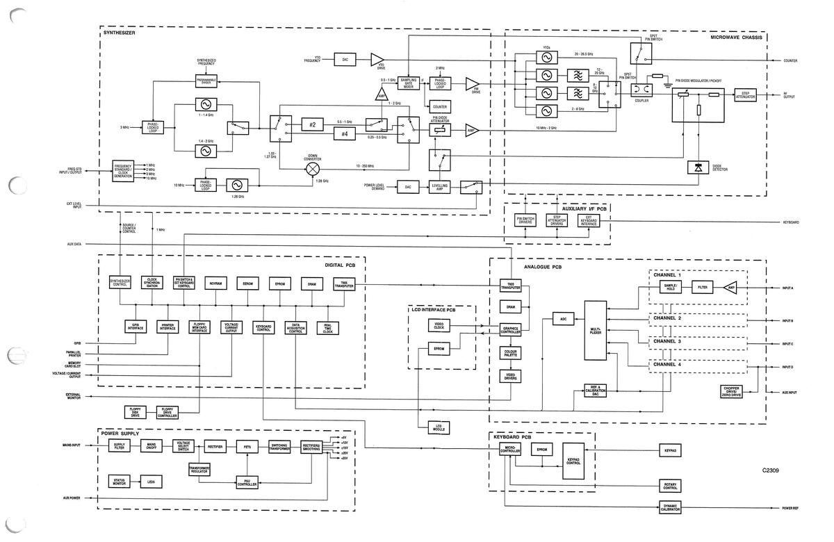
Fig. 1-1 Block Schematic Diagram of the MTS (6200B/6201B/6203B)
1-9
Block Schematic Diagram of the MTS 6200B/6201B/6203B

Fig. 1-2 Block Schematic Diagram of the MTS (6204B)

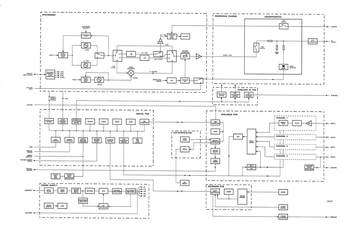
Fig. 1-3 Block Schematic Diagram of the 6202B RF Test Set

SYNTHESIZER
Introduction
The synthesizer, together with the microwave chassis, forms the MTS source. The synthesizer performs the following functions:
- (a) Signal generation in the range 10 MHz to 2 GHz.
- (b) YTO tuning and phase-locking in the range 2 8 GHz, 2 to 20 GHz or 2 to 26.5 GHz, depending on the instrument. This does not apply to the 6202B, which does not contain YIG oscillators.
- (c) Output level control.
- (d) Frequency counter.
The synthesizer module comprises four PCBs: RF, Control, Timebase and Synthesizer Power Supply Filter. The first three boards are inside the synthesizer tray; the Synthesizer Power Supply Filter board is mounted on the outside of the tray. Although not physically part of the synthesizer module, the Frequency Standard PCB will be described in this section since it is part of the synthesizer function.
The RF and Control boards are mounted either side of a floor in the synthesizer tray, and power and control connections are made via a 26-way ribbon cable which passes through a slot in the floor. Coaxial connections are used for the two RF signals, and the BFO tuning voltage passes through a feedthrough capacitor. The Timebase board is mounted above the Control board; all interconnections are via a 34-way ribbon cable.
In addition to the four boards, there is a microwave sampling gate mounted on the synthesizer tray. This is used as a down-converter for phase-locking the YTOs and also when the source is used as a frequency counter.
Overall Description
Figs. 1-1 to 1-3 show the functional connections to the synthesizer. All YTO supplies and tuning signals come from the Control board, but the SP5T and SP2T switches are driven by the Auxiliary Interface board. The Auxiliary Interface board also supplies the drive signals for the pickoff/switch assembly in the 6202B.
The detector which is connected to the pick/mod (combined PIN diode modulator and pickoff) is used for levelling over the full frequency range of the instrument. In a 6204B instrument, a 46 GHz diode detector is used for levelling above 2 GHz, and a 2 GHz pickoff is used below 2 GHz. Alternatively, the source can be levelled remotely using an external detector or power meter. The modulator in the pick/mod is only used above 2 GHz as it would generate excessive harmonics at lower frequencies. Below 2 GHz it is reverse-biased and a modulator on the RF board is used. This modulator is used for levelling in a 6202B instrument.
The SP2T switch connects a sampling gate mixer to either the 16 dB coupler for YIG locking, or a front panel connector (COUNTER) for frequency counting. In the 6202B, a switch within the pickoff/switch assembly isolates the sampling gate from the COUNTER input when the frequency counter is not required.
Fig. 1-4 is a simplified block diagram of the synthesizer tray, showing the main functions performed on each board. Nearly all connections with the rest of the instrument are via the Control board, the exceptions being the RF output from the RF board, the sampler RF input and the +5.1 V and +15 V supplies via the Synthesizer Power Supply Filter board.
The RF board generates output signals in the range 0.01 - 2 GHz, and also provides 0.5 - 1 GHz LO drive for the sampling gate. Two 1/2-octave VCOs cover the range 1 - 2 GHz. The VCOs' output is divided by 2 or 4 to extend the range down to 250 MHz. Coverage down to 10 MHz is achieved by mixing 1.03 - 1.27 GHz with the output from a 1.28 GHz BFO (beat frequency oscillator). A PIN diode modulator is followed by the output amplifier. The sampler drive is provided by a separate amplifier in the divide-by-2 path.
The dividers and phase comparators used to lock the VCOs are located on the Control board. The 1 - 2 GHz synthesizer uses fractional-N division to give high resolution with a single loop. A single YIG tune DAC is used; its output is switched into one of four drive amplifiers.
The level DAC output is compared with the voltage from either a detector on the microwave chassis or an external detector/power meter. The levelling loop is completed by either the modulator on the microwave chassis, or the modulator on the RF board for output frequencies below 2 GHz.
The YTOs are locked to harmonics of the sampler drive frequency. The IF signal from the sampler is filtered, amplified and divided by 64, then compared with a 2 MHz reference. The resultant error signal is amplified and applied to the YTO FM coils. The frequency counter works by counting IF frequencies derived from the sampler drive and input frequencies.
The control interface for the synthesizer tray is between the Control board and the Digital board, via a 34way ribbon cable. The Control board also monitors a number of voltages and status lines for calibration and diagnostic purposes.
The synthesizer tray uses 1, 2, 3 and 10 MHz as reference frequencies. These are derived from a 30 MHz VCXO on the Timebase board. When the MTS is set to internal standard, the VCXO is locked to an ovencontrolled crystal oscillator (OCXO) on the Frequency Standard PCB, and a 10 MHz output is provided on the rear panel (FREQ STD INPUT/OUTPUT). Alternatively, the VCXO can be locked to a 1 or 10 MHz external standard. A 1 MHz signal is sent to the Digital board, to lock the other frequencies used in the instrument.
RF PCB
Introduction
The RF board is required to generate signals between 10 MHz and 2 GHz at levels between -10 dBm and +7 dBm (+6 dBm for 6204B) at the front panel RF OUTPUT connector. Between the RF board and the instrument front panel there is the microwave chassis, which is used to generate signals above 2 GHz. The microwave chassis has an insertion loss of between 3 dB and 8 dB for signals between 10 MHz and 2 GHz. To ensure the correct front panel output level, the RF board must be capable of compensating for this loss. This gives a required RF board output power level between -7 dBm (-10+3) and +15 dBm (+7+8). The harmonic requirement of the output is -30 dBc, and this must be met over all of the previously derived output power level range. The simplified block diagram of Fig. 1-4 illustrates the various blocks which comprise the RF board.
The frequency range of the RF board is divided into a number of bands as shown below:
| Mixer band | 10 MHz - 250 MHz |
|---|---|
|
|
250 MHz - 500 MHz |
| ÷2 | 500 MHz - 1 GHz |
| Direct | 1 GHz - 2 GHz |
With the exception of the mixer band, each of these bands is again split into two bands each covering a half octave. This is because there are two VCOs on the RF board, each covering a half octave instead of a single VCO covering a whole octave, which would be harder to achieve. The ÷2 and ÷4 bands use pre-scalers to divide the 1 - 2 GHz signal from the VCOs by 2 or 4 to produce frequencies between 250 MHz and 1 GHz. Within the mixer band a signal from the lower 1/2 octave VCO is down converted by a mixer and local oscillator (BFO); filtering is then used to remove unwanted mixer products.

Fig. 1-4 Synthesizer
1-17

1-18
Hence the total number of bands is shown below:
| Mixer band | 10 MHz - 250 MHz |
|---|---|
| ÷4 lower 1/2 octave | 250 MHz - 350 MHz |
| ÷4 upper 1/2 octave | 350 MHz - 500 MHz |
| ÷2 lower 1/2 octave | 500 MHz - 700 MHz |
| ÷2 upper 1/2 octave | 700 MHz - 1.0 GHz |
| Direct lower 1/2 octave | 1.0 GHz - 1.4 GHz |
| Direct upper 1/2 octave | 1.4 GHz - 2.0 GHz |
VCOs
Circuit diagram: Fig. 7-9.
Two VCOs are used to give the required coverage of 1 - 2 GHz. Microwave amplifiers are used to increase the output level of the VCOs, and each oscillator has a low-pass filter to reduce unwanted harmonics.
Oscillators
In order to achieve the required coverage of an octave, two VCOs are used which together produce a signal between 1 GHz and 2 GHz, each VCO operating over half an octave. The first VCO, consisting of TR101 and associated circuitry, covers 1 GHz to 1.4 GHz, while the second, consisting of TR102 and its associated circuitry, covers 1.4 GHz to 2 GHz. These oscillators use a negative resistance technique to produce a sustained oscillation.
The base inductance L101 combined with internal transistor feedback makes the resistive component of the impedance looking into the emitter appear negative above a certain frequency. Hence power gain is available above this frequency. The tuned circuit consisting of L104, C105 and varactor D101 determine the frequency of oscillation. R106 to R108 form a 12 dB pad which helps to buffer the VCO from the following circuitry.
A microwave amplifier (IC101) running into compression is used to produce a constant output level over the VCO's operating frequency range. This level is reduced by the 3 dB pad (R136 to R138) to the required level. A printed low-pass filter (FL101) reduces harmonics of the wanted frequency to less than -40 dBc.
The second VCO, which consists of TR102 etc., is very similar to the first, but requires two varactor diodes to give the necessary frequency coverage.
These oscillators are referred to as the lower and upper half octave respectively. Only one of these oscillators is required to be on at a particular time. Transistors TR103/105 (for the lower half octave) and TR104/106 (for the upper half octave) are used to switch on the appropriate oscillator, as required by the Control board. D104 and R122 form a simple change-over switch which is used to route the signal from the selected oscillator through to the following common circuitry. This circuitry consists of a power splitter (R125 etc.), amplifier (IC105) and 6 dB pad (R142 etc.).
The output from R126, labelled "1-2 GHz RF", represents the major output, which is used by following circuitry to produce signals between 10 MHz and 2 GHz. The output from the 6 dB pad is routed via SKD to the Fractional-N loop on the Control board for locking purposes.
Direct and Divider Bands
Circuit diagram: Fig. 7-11.
To produce signals between 1 and 2 GHz, the output of the appropriate VCO is simply amplified/attenuated to the correct level.
To produce signals between 250 MHz and 1 GHz, two frequency dividers are used on the 1 - 2 GHz signal from the oscillators; a divide-by-2 and a divide-by-4. Four low-pass filters are used to reduce the level of harmonics on the output of these dividers; PIN diode switches are used to select the appropriate filter. Individual pads after each filter provide flexibility in setting the output levels of each of the divided frequency bands.
Direct Band Path
PIN diode package D302 is used to switch between the mixer band and the direct band; D301 is used to switch between the divide-by-2 band and the divide-by-4 band. Only one of these four bands can be selected at any one time, hence only one diode in these two diode packages can be biased on; the other three will be biased off. (One diode in each of these two packages is unused and has simply been bypassed.) The output of IC306 goes to almost +15 V to select the direct band path, which is via forward biased diodes in each of packages D302, D310, D311 and D304.
When the mixer or divider bands are selected, the isolation of this path is critical in determining the spurious or harmonic performance of the output respectively. Also, because of the large physical separation of D310 and D311 (approx. 11 cm), the microstripline which forms this path will have a resonance somewhere between 1 and 2 GHz.
To de-select this path, the output of IC306 goes to -15 V, which switches on shunt diodes D303 and D304. The previously forward biased diodes will now be reverse biased and vice-versa, hence a large amount of isolation will be provided. R333 and R334 are designed to terminate the microstripline when de-selected so that resonances are suppressed.
Dividers
IC301 divides the 1 - 2 GHz signal by two when selected by IC203D, TR303 and TR304, which close the switch consisting of 1/2 D301. IC203D is required to decode the control lines 1/2-1GHzX and SAMPLER DRIVE, because this divider is used in the 0.5 - 1 GHz band and also for production of the drive signal required by the sampling gate, which is used for YIG locking and frequency counting. R304, R337 and R338 form a 6 dB pad which ensures that the input level to the divider is within its limits. When these dividers have no input signal it is possible for self-oscillation to occur; this is prevented by TR304 and R304, which bias the input stage of the divider into a stable region when not in use.
IC302 divides the 1 - 2 GHz input signal by four when selected solely by the 250-500 MHz control line. Baluns T301 and T302 are used to convert the balanced ECL output of these dividers into a single ended output. The level of this output is approximately -8 dBm. The baluns are followed by microwave amplifiers running into compression to both raise and flatten the signal level as the output of the dividers reduces with increasing frequency. These amplifiers are switched off when not in use in order to reduce power consumption and heat generation.
Filters
The circuitry between D308 and D306 consists of two Chebyschev low-pass filters each terminated with a 10.5 dB pad. These filters form the path for signals between 500 MHz and 1 GHz, each used over half an octave. These filters are necessary in order to reduce harmonics of the chosen frequency. Similarly, the filters between D307 and D305 form the path for signals between 250 MHz and 500 MHz. However, the pads following these filters are only 9.5 dB as the output level of IC304 is lower than that of IC303.
IC203, 305 and associated circuitry provide decoding of the control lines and buffering to switch in the appropriate filter. The diodes at each end of the filter/attenuator constitute switches which are switched on/off together. The capacitors in series with the shunt arms of each pad are necessary for decoupling at RF since the DC control signal for the switches is injected here.
Mixer Band.
Circuit diagram: Fig. 7-12.
To generate signals between 10 MHz and 250 MHz, a down converter is used, which consists of a mixer and a beat frequency oscillator (BFO). A signal between 1.03 GHz and 1.27 GHz, supplied by the lower half octave VCO, is mixed with a fixed 1.28 GHz signal supplied by the BFO, to produce an IF signal between 10 MHz and 250 MHz. Filtering of this IF signal reduces unwanted spurious signals to acceptable levels.
Beat Frequency Oscillator
TR401 is the oscillator transistor tuned by the tank circuit consisting of L404, D401 and C403. This oscillator is similar to those described in 'VCOs', and functions in a similar fashion. The output level at TR401 collector is approximately +7 dBm. Unlike the VCOs, this oscillator is locked at a constant 1.28 GHz by a conventional phase locked loop resident on the Control board.
The loop filter consists of R418, C423 and C424 to give a loop bandwidth of approx. 10 kHz. A Zener diode D402 limits the tuning voltage to 12 V. This prevents the oscillator from oscillating much above 1.35 GHz, ensuring correct operation of the frequency divider in the phase locked loop on the Control board. A splitter consisting of R405 to R409 is used to provide the Control board with a small amount of the output - approximately -17 dBm. This is used to lock the BFO to the correct frequency. The major output of approximately -3 dBm is amplified by IC401 to provide the mixer X401 with approximately +8 dBm.
Down Converter.
The mixer X401 is used to down convert the 1.03 - 1.27 GHz input down to 10 - 250 MHz by mixing it with a fixed 1.28 GHz. The conversion loss of this process is approx. 8 dB. The source of the 1.03 - 1.27 GHz is the lower half octave VCO delivering approximately +2 dBm just before the -16 dB pad provided by R422-R424. TR412 and associated components form a 13.5 dB amplifier.
A 300 MHz low-pass filter immediately follows this amplifier to reduce spurious mixer products and breakthrough of mixer input signals. This is followed by another identical amplifier and filter to provide additional amplification and rejection. The final output of the down converter (10-250 MHz RF) goes to the attenuator and output amplifier. To reduce heat and power consumption, the BFO and down converter are only switched on when required. This is accomplished by TR409/410 etc., whenever the control signal 10-250 MHz is true.
Attenuator and Output Amplifier.
Circuit diagram: Fig. 7-10.
A voltage controlled attenuator is used before the amplifier in order to deliver the correct amount of power to the load. This attenuator provides typically 45 dB of range up to 2 GHz, and introduces less than -40 dBc of distortion at 10 MHz and -5 dBm.
The output amplifier is required to provide a substantial amount of gain and output power with low distortion. This amplifier's gain is typically 27 dB ±1 dB up to 2 GHz and distortion less than -30 dBc for output levels up to +15 dBm.
Input Selection
There are two inputs to the attenuator/amplifier; one is from the down converter (10-250 MHz RF) and the other is the combined outputs of the direct and divider bands (1/4-2 GHz RF). A PIN diode changeover switch (D206,207) is used to route the appropriate signal through to the attenuator and amplifier. IC204 is used as a comparator to level shift the output of IC203b, which represents 1/4-2 GHz valid, and to switch on the appropriate diodes which comprise this switch. The 10-250 MHz input has a 9 dB pad before the switch, which is required to terminate the filter in the down converter.
Voltage Controlled Attenuator
The attenuator uses PIN diodes D208 and D209 as current controlled variable resistors in a PI configuration. (The PI configuration exhibits much lower distortion and more range than a T configuration.) IC205 and IC206 etc. ensure that each PIN diode in the attenuator has the correct current and hence the correct RF resistance for any given input control voltage (LEVEL). The insertion loss of the attenuator at minimum attenuation is approximately 3 dB (flat) up to 1 GHz, increasing to 4 dB at 2 GHz.
Output Amplifier
In order to give the required gain and gain flatness to 2 GHz the amplifier consists of four gain stages. These four stages of gain are provided by IC202, TR202, TR204 and TR206. The gain of each of these stages is given below:
| 8 dB |
|---|
| 6 dB |
| 6 dB |
| 7 dB |
| 27 dB |
IC202 is a standard microwave amplifier, and the three transistor stages are standard feedback amplifier configurations. A 1 pF capacitor on the base of TR206 and a short/open circuit stub on the collector output line of TR206 help to improve the gain flatness at the top of the frequency range. The output of the amplifier is routed to the microwave chassis via SKF.
To reduce power dissipation, the amplifier is switched off when not in use. Transistors TR213, 201, 203, 205 are used to switch the individual stages on. IC203a,b,c is used to decode the control lines for each of the bands so that the amplifier can be switched on whenever any one of these control lines is true.
Sampler Drive Amplifier
Circuit diagram: Fig. 7-12.
This amplifier produces the necessary gain and output power for the drive signal between 500 MHz and 1 GHz as required by the sampling gate, which is used for locking YIGs and for frequency counting. The drive signal is derived from the divide-by-2 pre-scaler (Fig. 7-11). An input level of more than +10 dBm ensures that the first amplifier, IC501, is well into compression (gain > 10 dB, 1 dB gain compression level < 18 dBm).
The second stage, IC502, has only 8.5 dB gain typically and 23 dBm compressed output level. Again, this stage is well into compression. Resistors R508 and R509 form an inverted-L attenuator, which helps to match the output of IC502 to the input of the sampling gate and also ensures that the correct power level reaches the sampling gate.
To conserve energy and reduce heat, this amplifier is switched off when not used. TR501-503 are used to switch the amplifiers on and off as required by the SAMPLER DRIVE RF line, which carries both the RF signal and the DC control signal.
UHF Reference and Loop Filters
Circuit diagram: Fig. 7-9.
The UHF PLL (Phase Locked Loop) operates with a 3 MHz reference frequency; this is the highest easily-derived frequency which allows all frequencies above 1 GHz to be generated by the Fractional-N synthesizer. In sweep mode the loop bandwidth is about 50 kHz, for fast settling. In CW mode the loop bandwidth is about 2 kHz, to reduce fractional-N products.
Filters and Loop Bandwidth Switching
The phase comparator drives a switched current source, located on the Control board. When the loop is locked the current source output is a square wave: ±2.5-5 mA in sweep mode and ±250-500 µA in CW mode.
In sweep mode, the reference filter (bounded by C601 and C603) has 415 kHz bandwidth. The loop filter is formed by R603 and C604. In CW mode the VCO tuning signal also passes through the 8 kHz filter bounded by C605 and C608, and the loop filter comprising R604, C609 and C610. Two electrolytic capacitors, connected back-to-back, are used in case the tune line goes negative. Two inductors are used for each filter element, fitted back-to-back to minimise magnetic pick-up from the PSU and display. IC602b, IC602c and IC602d select or bypass the 8 kHz low-pass filter for low or high bandwidth respectively.
Force VCO Tune
The programmable divider on the Control board is not guaranteed to work for input frequencies above 2 GHz. Also, it can oscillate if it has no input signal. However the VCOs may stop oscillating if the tuning voltage is too low, and the 1.4 - 2 GHz VCO can oscillate above 2 GHz. Both of these conditions must be avoided or the loop may latch up and fail to lock.
To prevent this happening, the VCO varactor voltage is forced to a value in the middle of its range (about 10 V) for a short period every time a byte is written to the fractional-N ULA. This is done by IC601a and IC602a, and the period is set by IC603. For high bandwidth the pulse width is 10 µs and for low bandwidth it is 1 ms. The longer period is needed to charge C609 and C610.
Loop Gain Compensation
The PLL bandwidth is proportional to the VCO sensitivity and inversely proportional to the frequency. Over the half-octave tuning range the sensitivity of each oscillator reduces by about 1.4. Thus without any compensation the loop bandwidth at the top of each VCO band would be about half what it was at the bottom.
The nominal tuning voltage range for the VCOs is from 2 to 15 V. IC601b and its associated resistors produce -7.8 to -10.1 V for 2 to 15 V input. This is fed back to the tail of the switched current source (Control PCB, Sheet 7), varying its current output by a factor of two and hence maintaining a roughly constant loop bandwidth.
VCO Tuning Monitor
IC601c, etc. gives an output in the range 0 to +5 V for varactor voltages in the range 0 to +25 V. This is routed to the ADC on the Control board for diagnostic purposes.
CONTROL PCB
Introduction
The Control board performs the following functions:
- YIG tuning and bias switching.
- Output levelling in both synth. and YIG bands.
- Fractional-N division, locking and control of the UHF synthesizer.
- Locking the BFO.
- Sampler IF processing (amplification, ALC, filtering, switching, etc.).
- YTO locking.
- Frequency counting.
- Bi-directional interface with the digital board; decoding source control instructions, monitoring and reporting various voltages and status signals.
References to YIG oscillators and associated circuitry do not apply to the 6202B, since it does not contain any YIG oscillators. The functional blocks of the Control board are shown in Fig. 1-4.
YIG Tuning and Bias Switching
Circuit diagram: Fig. 7-52, 7-54, 7-59.
The YIG oscillators are current tuned. For the 2 - 8 GHz, 8 - 12 GHz and 12 - 20 GHz oscillators, the sensitivity is approximately 20 MHz/mA. For the 20 - 26.5 GHz YTO it is about 30 MHz/mA.
A P-channel/N-channel MOSFET pair is used as the output stage of the YTO driver. R207 is a current sense resistor; the transconductance of the driver is defined by R201, R205 and R207. Low temperature coefficient resistors are used to minimise tuning current variation with temperature. IC213 is a 16-bit DAC; thus the nominal tuning sensitivity is 1 LSB = 500 kHz below 20 GHz, and 750 kHz above 20 GHz.
C213 is connected across the YIG tuning coil (the CW filter) to reduce residual FM due to noise on the tuning current. It slows down the driver however, so it can only be used in CW mode or with very slow sweeps.
Component numbers in the following description refer to the 2 - 8 GHz driver; all drivers are identical. The driver is selected by IC203. When not selected, the tuning current is zero, due to R208. D204 and D205 limit the back e.m.f. when the driver is switched off. The 36 V Zener (D205) speeds up the collapse of tuning current, during retrace, etc.
A logic high at R210 turns on the CW filter. TR201 and TR202 act as a level shifter to provide gate bias to switch TR207 and TR208 on and off. D208 limits Vgs on TR207 and TR208.
All tuning currents are returned via the current sense resistor R207.
The circuitry round IC221 and TR220 provides a regulated -18 V supply for the YTO drivers. The drivers need a clean supply because of the tuning sensitivity of the YIGs; it should also be as high a voltage as is practical, as the current slew rate and hence the sweep speed, are limited by the available voltage and the tuning coil inductance.
In order for the YIG loop to lock, only one YTO at a time must be powered (the heaters are powered continuously to maintain the YIG temperature). The +15 V bias is switched by TR951-TR954. Quad comparator IC952 is used as a level shifter to derive gate bias voltage from the logic-level band select lines. The 2 - 8 GHz YTO also requires -5 V bias; this is supplied by IC951.
Output Levelling
Circuit diagram: Fig. 7-53, 7-54.
A simplified representation of the levelling loop circuitry is shown in Fig. 1-4. IC218 selects internal or external detector; either polarity of external input can be selected. IC219 and IC220 are connected as a differential amplifier with a gain of 19 and a high CMRR. This configuration is used in order to minimise residual AM at low power levels, when the detector voltage is very small.
IC220 output is compared with the output of the 16-bit level DAC IC214 to produce an error voltage, which is amplified by IC204. A small offset voltage is applied via R235. This ensures that the output of IC204 will be negative if the DAC voltage and detector voltage are zero, and therefore guarantees that a DAC code of zero will give maximum attenuation.
IC210 is an integrator with different switched gains, controlled by IC209. The settling time is determined by the loop bandwidth, which is the frequency at which the open-loop gain equals 1. There is considerable variation in maximum output power, even within each band, so the slower the loop settles, the more ripple there will be on fast sweeps. It is therefore important to keep the loop gain as high as possible. In general, settling is slowest at low output powers.
Normally C232 is not connected. Below 2 GHz R242 is selected. Above 2 GHz or with an external detector, R243 and R241 are selected (the FET TR104 is only present on later instruments). R243 is adjusted for the fastest settling consistent with loop stability. If a power meter is used for external levelling, it will have a much longer response time than a detector, so the overall loop bandwidth must be reduced to prevent instability. R240 and C232 are then selected.
In between points in a sweep, the input is disconnected from IC210 to hold the modulator setting until the frequency has almost settled. This is done by a logic high on the LEVEL HOLD input, which sets pin 9 of IC205 high. IC205 decodes the control lines which determine the levelling loop mode.
IC211 selects the appropriate modulator. In the YIG bands the modulator on the RF board is driven with +15 V via R249, which gives maximum attenuation. Below 2 GHz the input to IC216a is pulled negative by R247. This sets the microwave modulator to minimum attenuation, hence giving minimum distortion on the low frequency signals passing through it. When maximum attenuation is required (for AC detection, etc.), IC216a input is pulled positive by R248.
IC216b and its associated circuitry is used to compensate for the non-linearity of the microwave modulator, and hence to reduce the worst-case settling time. The P-N junction (IC222b) gives IC216b an exponential gain characteristic, which increases the gain as the input becomes more positive, ie. when more attenuation is required. IC222c, IC216c, etc. produce an offset which matches the voltage drop across IC222b.
The microwave modulator is current driven; this gives less non-linearity than voltage drive. IC216d is connected as a unity-gain differential amplifier to feed back the voltage developed across the sense resistor R290. This configuration enables a grounded load to be current driven.
The 'unlevelled' detector is a window detector. If IC210 output goes outside the range ±9.9 V, the output of IC212b goes high.
Fractional-N Synthesizer
Circuit diagram: Fig. 7-57, 7-58.
Fig. 1-5 is a block diagram of the fractional-N synthesizer. The system used provides fine frequency resolution without needing analogue correction or compromising the phase detector speed.
The 1 - 2 GHz input at SKK passes through a 6 dB pad, a buffer amplifier (IC509) and a 6 dB pad to provide reverse isolation, before reaching the pre-scaler, IC510. This, in conjunction with buffering on the RF board, ensures that sub-harmonics, etc. generated by IC510 are kept below -60 dBc on the output signal. IC510 divides the input frequency by four, since IC511 is only specified to 500 MHz.
IC502 and IC503 are connected to form a 5-bit programmable counter (/N1), and IC504 is a 3-bit programmable counter (/N2). N1 and N2 are set by the fractional-N controller ULA, IC501. R502-509, R511 and R512 convert the CMOS output levels from IC501 to the ECL voltages needed for the load inputs of IC502-504.
At the start of a count, IC511 divides by 9. When IC504 reaches terminal count, it disables itself and sets IC511 to divide by 8. The count continues until IC502 and IC503 reach terminal count, at which point the new values of N1 and N2 are loaded via IC505d. The overall division ratio is therefore 4(8N1 + N2). The terminal count of IC502 and IC503 also clocks the phase comparator input IC507 pin 11, via the level shifter formed by TR501, TR502, etc. When the new value of N1 is loaded, IC501 is clocked via IC505b, IC505c, TR503 and TR504 to output the next values of N1 and N2.
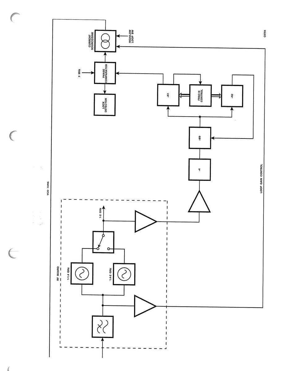
Fig. 1-5 Fractional-N Synthesizer
IC506a, IC507b and IC508 form a 4-state phase comparator which is run at 3 MHz. The synthesizer produces fractional-N related phase noise which increases in amplitude with increasing offset from the carrier, and whose spectrum is proportional to the loop reference frequency. It is removed by means of a low-pass filter on the VCO TUNE line. The higher the reference frequency, the higher the loop bandwidth can be made (giving faster settling) without incurring significant fractional-N products. 3 MHz is the highest simple frequency which gives full coverage of the 1 - 2 GHz range with the divider configuration used.
The circuitry comprising IC506b, IC507a and TR505 forms a lock detector. If more than π radians of phase error accumulates, TR505 is switched on.
TR506, TR507, TR508 and their associated components act as a symmetrical current source/sink, which is switched by the complementary phase detector outputs. IC512 switches the magnitude of the sourced/sunk current, and hence the loop gain, by a factor of 10. A negative voltage derived from the VCO tuning voltage is fed back at PLB pin 8. This causes the output current to increase with increasing VCO voltage, and helps to compensate for the effect on loop bandwidth of divider ratio and variation in VCO sensitivity. For 5 - 15 V tuning voltage, the current is ±(250 - 500) µA or ±(2. 5- 5) mA. The switched-current output is filtered on the RF board to derive the VCO tuning voltage.
The loop gain switching, combined with further gain and filter switching on the RF board, gives a loop bandwidth of either 1 - 2 kHz or about 50 kHz. Low loop bandwidth is used in CW mode to give reasonable phase noise. In swept mode, high loop bandwidth is selected to give fast settling (within 100 kHz in 250 µs at all frequencies up to 26.5 GHz).
BFO Phase-Locked Loop
Circuit diagram: Fig. 7-53.
The BFO is a VCO on the RF board, which is locked to 1.28 GHz by circuitry on the Control board. The RF input frequency at SKL is divided by 64 by IC401, to give 20 MHz. When the BFO is turned off, the input to IC401 is biased via D401 to prevent self-oscillation. TR401 and TR402 convert the differential ECL output from IC401 to a CMOS compatible level. IC402a divides the 20 MHz by two.
IC403 and IC404 form a 4-state phase comparator which is run at 10 MHz. When the BFO is locked, IC404 pin 6 and IC404 pin 8 give complementary 10 MHz outputs, whose mark/space ratio depends on the phase relationship between the two inputs to the phase comparator. The circuitry comprising IC405 and TR406 forms a lock detector, which gives a logic high output if more than π radians of phase error is accumulated.
TR403-405 and their associated components act as a switched current source/sink, giving +3 mA output at SKM. This is filtered on the RF board to derive the BFO tuning voltage. The loop bandwidth is about 10 kHz, which gives the best compromise between VCO noise and divider noise.
When the BFO is turned off, TR403 base is pulled low via D401, forcing the tuning voltage down to 3 V. This ensures that when the BFO is turned on, it starts oscillating at a low frequency. This prevents the latch-up which could otherwise occur, as IC401 is only guaranteed to work up to 1.3 GHz.
Sampler IF Amplifier and Filters
Circuit diagram: Fig. 7-60.
The sampling gate is used in source mode above 2 GHz and also in frequency counter mode. In source mode the SAMPLER IF signal clocks the input divider in the YIG PLL. In counter mode, LO frequencies in the range 0.5 - 1 GHz are used to produce an IF frequency of about 100 MHz, and the software performs cross checks to eliminate errors. Input frequencies below 400 MHz are counted directly, with the LO set to 1 GHz. The sampler includes an IF amplifier stage which requires bias current; this is provided via R701 and R702.
C703, L701, C704, L702 and C705 form a 410 MHz low-pass filter which rejects LO breakthrough, and images (>600 MHz) when in direct count mode. LO filtering is needed at the input because the LO level may be higher than the wanted signal. Without an input filter the following ALC amplifier could therefore level on the LO rather than the IF.
For the frequency counter the IF input level may be anywhere in the range -50 to 0 dBm. The IF amplifier must therefore have sufficient gain and a wide dynamic range. The amplifier used has wide-range automatic level control, and comprises IC701-703 and associated components. The overall gain is about 60 dB at 410 MHz and higher at lower frequencies. (The amplifier bandwidth must be at least 410 MHz, but in IF count mode image frequencies can fall within this band. A limiter cannot therefore be used at this stage as it would generate in-band intermodulation products which would affect counter operation.)
D703, R716 and C717 form a peak detector. The levelling loop is completed by IC704 and PIN modulators D701 and D702. The levelled output is between +5 and +10 dBm over the range 10 - 400 MHz.
IC706d provides an IF level monitor output to the ADC. This is used in counter mode when the software is trying to determine whether it has got any input signal to count. If there is no input the amplifier will be at maximum gain and the monitor output voltage will be about 4.5 V. As the input level is increased the amplifier gain, and hence the IF monitor voltage, will be reduced.
In direct count mode the IF bandwidth must be at least 400 MHz. In YIG lock mode and most of the time in counter mode, further filtering is needed to reject images generated by LO frequencies down to 500 MHz. This is provided by the 280 MHz low-pass filter comprising C724-726, L703 and L704, and the path switching for the counter is done by D704 and D705, driven by IC706a and IC706c.
C728-732 and L705-708 form a 66 - 256 MHz band-pass filter. The level out of the filter is compared with a fixed threshold voltage by D707, D708, IC706b, etc. As the IF is levelled, the comparator acts as a frequency window detector and gives a logic high output if the IF frequency is in the range 65 - 265 MHz. This is used in counter mode to aid IF acquisition. The YTO phase-locked loop IF input (YIG PLL IF) is taken from after the band-pass filter via a 6 dB pad.
The signal to be counted passes from D705 via a 3 dB pad to IC705. The filtered path between D704 and D705 has about 8 dB more loss than the "straight through" path. As the counter's front end has only a 6 dB guaranteed operating window, more gain and level control are needed. By this time, non-harmonically related frequencies (LO and image) should have been sufficiently attenuated, so a limiter can be used. IC705/D706 acts as the limiting amplifier.
IC701-703 and IC705 are turned off by TR701 and TR702 when the sampler is not in use, to reduce heat generation and spurious products.
YTO Phase-Locked Loop
Circuit diagram: Fig. 7-59.
Fig. 1-6 shows the overall operation of the YTO PLL. The selected oscillator is tuned to the nominal required frequency using the tuning coil and pulled to the exact frequency by means of the FM coil.
The YTO output frequency is fed via a coupler into the sampler, which generates sum and difference products of the YIG frequency and all harmonics of the LO frequency. The LO frequency, fL, is in the range 600 - 800 MHz. After being amplified and filtered, the IF is divided by 64 and compared with a 2 MHz reference. The loop locks when the YTO frequency = NfL + 128 MHz.
The phase comparator output passes through the reference filter and loop filter to the FM drive amplifier. The multiplying DAC compensates for the difference in FM sensitivity between YTOs to maintain a constant loop bandwidth.
IC601 divides the IF frequency by 64. R601 biases its input to prevent self-oscillation when there is no input signal. TR601 and TR602 convert the differential ECL output to CMOS compatible levels.
IC602 and IC603, together with R610-614 and C606, form a 4-state phase comparator which is run at 2 MHz. Incorporating the outputs from IC602 pin 6 and IC602 pin 9 gives the phase comparator a linear range of ±3π radians and increases the loop's slew rate by a factor of about two.
IC606b, IC607b, IC607a, etc. act as a window detector which detects when the loop is out of lock. When it is in lock, the integrator input voltage is zero. If the loop fails to lock, this voltage will be in the range ±(0.7 - 2.1) V. The lock detector gives a logic high output if its input voltage is outside the range -0.27/+0.2 V.
C608, L601, L602 and C609 form a 400 kHz reference filter. The loop filter comprises IC606a and its associated components. In normal operation the YIG PLL has about 50 kHz loop bandwidth and 13 kHz integrator break frequency. The software sets the required loop bandwidth by adjusting the digital inputs of the multiplying DAC, IC608, to give an FM sensitivity of 4 MHz/V at its Vref input. IC606c and the associated resistors provide an FM drive monitor signal which is used during YTO frequency calibration and FM sensitivity calibration.
YIG FM sensitivity calibration is performed with lower loop bandwidth to ensure loop stability, so the integrator break frequency is reduced to 4.6 kHz by switching in C610.
At band changes and when changing frequency in CW mode, the FM drive is momentarily set to zero to stop the loop latching up. This is done by shorting the integrator feedback network via IC605b.
In between successive frequency points in a sweep, the FM drive is held constant for about 140 µs by opening IC605c and IC605d. The integrator is left holding the voltage on C611. This allows the YTO and the UHF synthesizer to settle before the loop is closed, and hence reduces the loop slewing time (assuming very little difference in YIG cal error between successive points). The time constant is produced by IC604a, which is triggered by writing to the YIG frequency DAC.
In AC detection mode the FM drive is also held during the "power off" periods, by means of the FM HOLD signal which is set by software.
The FM drive amplifier consists of IC608, IC606d and IC609. The digital inputs of multiplying DAC IC608 set the amplifier's gain. The DAC has current output and therefore needs an op amp to follow it. IC609 is a high-power unity-gain buffer and is included within the DAC feedback loop. The YTO FM coils are connected in series, and the voltage across current-sensing resistors R630 and R631 is fed back to the DAC. D602 and D603 limit the output current to ±150 mA.

Fig. 1-6 YTO Phase-Locked Loop
0
C
E
Frequency Counter
Circuit diagram: Fig. 7-55.
The counter section of the board is required to count frequencies in the range 10 - 400 MHz. It consists of a counter with serial input and parallel output, and a gate timer which sets the duration of the count.
The gate timer is a 24-bit programmable counter comprising IC101-103. The gate time is loaded as an LS word and an MS byte. The timer is clocked at 1 MHz, which gives a maximum possible gate time of 16.7 s. As the longest gate time set is 1 s, the top four bits are not used.
The timer is started by a rising edge on IC105 pin 3, which causes IC105 pin 5 to go low. On the next rising edge of the 1 MHz clock, IC104 pin 6 goes low, enabling IC103 and IC107 to start counting and setting IC105 pin 5 high again. When the timer reaches terminal count, IC104 pin 9 goes high on the next falling edge of the 1 MHz clock, and on the next rising edge IC104 pin 6 goes high, disabling IC103 and IC107. The actual gate time is therefore 1 µs longer than the value loaded into IC101-103.
The gate timer control as described above is needed to de-glitch the terminal count output of IC101, and also to minimise the skew between delays in opening and closing the gate, which could cause significant inaccuracy when counting 400 MHz.
The counter proper consists of a 4-bit BCD counter (IC107) and a 28-bit binary counter (IC108, IC110-112). The carry output of IC107 is used to clock IC108, and IC105(b) pin 9 clocks IC110-112, which are connected as a 24-bit synchronous counter. Diode D105 is used as an OR gate. The outputs of IC107 and IC108 are output to the data bus by tri-state buffer IC109. IC110-112 incorporate tri-state output registers. The count value is read as two 16-bit words. After it has been read, the counter is cleared by setting the TRIGGER/RESET line low again.
Apart from the inhibit input, all IC107's inputs and outputs are level shifted to interface with CMOS logic. TR101 and TR102 provide the fast interface needed to clock IC108 at up to 40 MHz. Speed is not important for the other outputs.
The actual count sequence output to the data bus for the LS nibble looks like this:
| Count | Output | ||
|---|---|---|---|
| 0 | 1000 (8) | ||
| 1 | 1001 (9) | ||
| 2 | 1010 (10) | ||
| 3 | 1011 (11) | ||
| 4 | 0100 (4) | ||
| 5 | 0101 (5) | ||
| 6 | 0110 (6) | ||
| 7 | 0111 (7) | ||
| 8 | 0000 (0) | ||
| 9 | 0001 (1) | ||
IC108 is clocked on the count of 4, i.e. 6 counts too early, but since all codes in the sequence are unique, the software is able to determine the correct frequency count.
Digital Board Interface
Circuit diagram: Fig. 7-56.
The interface with the Digital board is via PLA, and consists of a 16-bit bi-directional data bus (SD0-SD15), an 8-bit address bus (SAD0-SAD7), write and read strobes (SWR and SRD) and a synthesizer select line (SSEL). SWR, SRD and SSEL are active low. SD0 - SD15 and SAD0 - SAD7 correspond to D16 - D31 and A2 - A9 respectively, on the Digital board. There is also a 1 MHz reference output from the synthesizer; all the other clocks in the instrument are locked back to it. The software interface is as follows:
SAD7 and SAD6 define the general type of write or read operation.
| 0000XXXX | Write to synth tray (except frac-N ULA) |
|---|---|
| 01XXXXXX | Write to frac-N ULA |
| 100000XX | Read from synth tray (except ADC) |
| 11000000 | Read ADC |
Note...
C
Unless otherwise stated, data is +ve logic, i.e. 1 = true.
WRITE OPERATIONS
| Address | Function | Remarks | ||
|---|---|---|---|---|
| 00H | YIG frequency |
16 bits.
Scale: |
LSB SD0
2 - 20 GHz LSB = 500 kHz 20 - 26.5 GHz LSB = 750 k |
nominal
Hz nominal |
| 01H | level | 16 bits. LS | B SD0 | |
| 02H | mode byte 1 |
8 bits
SD0-SD2 SD3 SD4 SD5 SD6 SD7 |
timebase control
int/ext detector +ve/-ve detector detector/power meter counter reset/trigger YIG loop break freq |
0 = int
0 = +ve 0 = detector 0 = reset 0 = high |
| break freq | ||||
| Timebase co | ontrol codes: | |||
| 000 | OCXO internal standard |
001
010
011
100
101
110
111
1 MHz external standard
10 MHz external standard
MTS standard cal
MTS internal standard (VCXO) (not used in 6200B)
not used
not used
not used
| 03H | mode byte 2 |
6 bits
SD0 SD1 SD2 SD3 SD4 SD5 |
CW filter
UHF loop bandwidth max attenuation level hold FM hold FM zero |
1 =
1 = 1 = 1 = 1 = |
filter on
low BW max atten level held FM held FM zeroed |
|
|---|---|---|---|---|---|---|
| 04H | band select |
14 bits
SD0 SD1 SD2 SD3 SD4 SD5 SD6 SD7 SD8 SD9 SD10 SD11 SD12 SD13 |
10 - 250 MHz
250 - 500 MHz 0.5 - 1 GHz 1 - 2 GHz sampler drive 2 - 8 GHz 8 - 12 GHz 12 - 20 GHz 20 - 26.5 GHz 20 - 26.5 GHz lower 1/2 octave upper 1/2 octave direct count count/YIG lock |
|||
| 05H | FM gain | 8 bits. LSB | SD0. | |||
| 06H |
counter gate time
(LS word) |
16 bits. LSB SD0.
LSB = 1 μs |
Ì |
Set gate time to
required time - 1 μs |
||
| 07H |
counter gate time
(MS byte) |
8 bits. LSB SD0
LSB = 1 µs × 2 16 |
||||
| 08H |
freq std tune
(coarse byte) |
8 bits. LSB SD0 | ||||
| 18H |
freq std tune
(fine byte) |
8 bits. LSB SD0 | ||||
FRAC-N ULA
| Address | Function | Remarks |
|---|---|---|
| 40H-7FH | all ULA functions |
8 bits. LSB SD0
All ULA functions can be set by software. |
READ OPERATIONS
| Address | Function | Remarks | |
|---|---|---|---|
| 80H |
freq counter
(LS word) |
16 bits. LSI | B SD0 |
| 81H |
freq counter
(MS word) |
16 bits. LSI | B SD0 |
| 82H | status | 10 bits | |
| SD0 | unlevelled | ||
| SD1 | UHF out of lock | ||
| SD2 | YIG out of lock | ||
| SD3 | not used | ||
| SD4 | BFO out of lock | ||
| SD5 | freq std out of lock | ||
| SD6 | no std. | ||
| SD7 | timebase phase detector output | ||
| 1 = int std freq high | |||
| SD8 | freq counter IF valid | ||
| SD9 | count finished. Goes to 0 <1 µs after | ||
| counter trigger (mode byte 1) |
ADC
Address C016
Sequence:
- 1. Write cycle to load MUX code
- 2. Dummy read cycle to start conversion
- 3. Wait >2.5 μs
- 4. Read cycle to read ADC
MUX codes:
3 bits. SD0-SD2
- 000 not used
- 001 VCO tuning voltage
- 010 YIG FM drive
- 011 freq. counter IF level
- 100 not used
- 101 VCXO tuning voltage
- 110 not used
- 111 not used
All the Digital board outputs to the synthesizer are via tri-state buffers, which are only enabled when the synthesizer is addressed. This reduces the level of digital interference on the source output. The Control board has pull-up resistors on all these lines.
SAD7 and SAD6, which define the write/read mode, are decoded by IC901a. The decoded outputs are ANDed (negative logic) with SWR or SRD to produce local write and read strobes. IC901 pin 4, in conjunction with SWR, enables IC903, which decodes SAD0 - SAD3 to generate most of the write strobes used in the synthesizer tray.
IC901/5 selects the Fractional-N control ULA, and SWR strobes data into it. IC901/5 is also ANDed with SWR to give the signal FORCE VCO TUNE. This forces the selected VCO to the middle of its tuning range whenever any fractional-N parameter is changed, ensuring that it oscillates at a sensible frequency and avoiding the possibility of the loop latching up.
IC901/6 enables IC901b, which decodes SAD1 and SAD0 to read the frequency counter and the status word.
IC901/7 selects ADC operations. IC910 is an 8-bit ADC with a built-in 8-channel analogue multiplexer. IC901 pin 7 in conjunction with SWR loads the MUX address into IC908. When ANDed with SRD it starts the conversion and then reads the data (two read cycles are needed).
TIMEBASE PCB
Circuit diagram: Fig. 7-65.
Introduction
The Timebase board generates the reference frequencies used in the source, as follows:
| 1 MHz | Clock for gate timer in frequency counter. Also used as a sync signal by the Digital board. |
|---|---|
| 2 MHz | Phase comparator reference frequency in YIG PLL. |
| 3 MHz | Phase comparator reference frequency in fractional-N PLL. |
| 0 MHz | Phase comparator reference frequency in BFO PLL. |
These frequencies are produced by dividing down the output of a DAC-tuned 30 MHz voltage controlled crystal oscillator (VCXO). This oscillator can be phase-locked to either an internal 10 MHz oven-controlled crystal oscillator or to an external 1 MHz or 10 MHz standard. When the instrument is operating on internal standard a 10 MHz output is provided at the rear panel.
Operating Modes
The mode of operation is determined by a 3-bit code, TBC0 - TBC2. The modes are as follows:
TBC 210
| 000 | OCXO internal standard |
|---|---|
| 001 | 1 MHz external standard |
| 010 | not used |
| 011 | 10 MHz external standard |
| 100 | MTS internal standard (VCXO) |
| 101 | MTS standard cal. |
| 110 | not used |
| 111 | not used |
The VCXO is locked in modes 000, 001 and 011, but not in modes 100 and 101. Thus TBC2 determines whether the VCXO is DAC-tuned, or or phase locked to the OCXO or an external standard. In locked modes the loop bandwidth is about 50 Hz.
In the cal mode the phase comparator is used as a frequency comparator between a 10 MHz external standard and 10 MHz derived from the internal standard. The internal standard is tuned by successive approximation under software control. When the VCXO is locked to an external standard the phase comparator is operated at the external standard frequency, i.e. 1 MHz or 10 MHz.
IC11 provides a 10 MHz output when the instrument is locked to its internal standard, selected by code 100. IC10b provides additional isolation.
Instruments prior to the 6200B series did not contain an OCXO so mode 000 was unused; mode 100 was used when operating on the internal standard (DAC-tuned VCXO). In the 6200B the DAC-tuned OCXO (mode 000) is used instead because of the improved performance.
Oscillator Tuning
IC1 is a dual 8-bit DAC, configured to give coarse and fine bytes with a weighting of 43:1. This is the optimum ratio for the cal. routine. The 0 to +5 V output provided by IC2d is used for tuning the OCXO. IC2c gives 0 to +12.5 V to tune the VCXO.
IC3a, R8 and R9 provide an attenuated version of the tuning voltage to the ADC for diagnostic purposes. IC3b, TR1, etc. close the PLL when TBC2 is 0, overriding the DAC output.
30 MHz VCXO
TR2, XL1, D2 and the associated components form a Colpitts oscillator with a pulling range of about ±3 kHz. TR3 buffers the oscillator output and amplifies it to a level sufficient to drive IC4a, a Schmitt inverter.
Frequency Division
IC5 divides the 30 MHz by 10. The counter is synchronously loaded with 6 when the TC output goes high, so it counts from 6 to 15. IC6 is configured as a synchronous divide-by-3, to give 10 MHz. IC7a divides the 10 MHz by 5 and 2 to give 2 MHz and 1 MHz.
Phase/Frequency Comparator and PLL
IC12 and IC13 form a 4-state phase comparator. When the loop is in lock the output at IC13/8 is at the reference frequency, with a mark/space ratio dependent on the phase relationship between the input signals. Advancing the phase at IC12/11 increases the mark/space ratio. If the frequency at IC12/11 is higher than that at IC12/3, IC13/8 will be permanently high (with glitches). The output at IC13/6 is the complement of that at IC13/8.
The phase comparator input signals are selected by IC10a and IC8. IC10a selects either 10 MHz OCXO or external standard. IC8 selects either 1 MHz or 10 MHz derived from the VCXO, or 10 MHz from the OCXO. In modes where the phase comparator is not used, IC12/11 is held low. IC9a and IC9d are differential receivers for the external frequency standard inputs. The receiver inputs are internally biased to ensure stability in the absence of a signal. With no input, the output is high.
IC14a and its associated components form the loop filter and provide the VCXO tuning voltage. When locking to a 1 MHz external standard TR4 is turned off, increasing the gain to compensate for the increased division ratio. IC14c decodes the control inputs, to turn TR4 off only when the control code is 001.
IC14b, IC14d, D7, etc. act as a lock detector. When the loop is locked the loop filter input will be at 0 V; if it is out of lock it will be +1 V or -1 V. The window detector gives a high output if its input is outside the range ±0.5 V.
IC9b is used when calibrating the internal standard. It gives a high output when the internal standard frequency is high, i.e. when IC13/6 is low. A two cycle delay at the difference frequency (w.r.t. 10 MHz) is required before reading IC9b, as the phase comparator can accumulate up to 3π radians of phase error and has a linear range of ±π radians.
D4, C11 and R2 4 form a peak detector. In the absence of an external standard input, IC9/5 is high; IC9/5 goes low for input frequencies above about 150 kHz.
SYNTHESIZER POWER SUPPLY FILTER PCB
Circuit diagram: Fig. 7-67.
This board provides some extra filtering on the +5.1 V and +15 V supplies, to help reduce the level of supply sidebands on the source output. Extra filtering on the other supply rails is not needed.
FREQUENCY STANDARD PCB
Circuit diagram: Fig. 7-78
This board contains the 10 MHz oven-controlled crystal oscillator (OCXO) which provides an accurate internal frequency standard for the instrument. Overall operation of the frequency standard (both internal and external) is explained earlier in this chapter.
The +15 V power for the board is derived from the PSU via the Synthesizer Power Supply Filter PCB, with additional smoothing provided by C1. The supply to the OCXO is via 12 V regulator IC1 and associated components.
PLRL pin 9 carries the OCXO TUNE signal from the Timebase PCB (via the Control PCB). The output at TTL levels to the SMB connector PLRM supplies the OCXO standard to the Timebase PCB. The relay control line on PLRL pin 2 is not used, and the relay contacts are permanently closed during operation.
ANALOGUE PCB
Introduction
Referring to Fig. 1-7, it can be seen that the MTS data acquisition system comprises four fully differential amplifier chains. One of these can be configured as either a differential DC amplifier or a chopper amplifier front end compatible with 6900 series power sensors. All differential amplifiers are software zeroed via a 12-bit DAC; the chopper amplifier (part of which is within the sensor) is zeroed by a voltage passed to the power sensor derived from a 16-bit DAC.
Each amplifier chain has two gain stages with eight settable ranges, followed by a switched filter and discrete sample and hold. All channels then pass through a 16 channel multiplexer into a 16-bit A to D converter, the serial output of which is fed to the Digital board for decoding and processing.
Calibration of the data acquisition system (DASystem) is performed by the same 16-bit DAC that is used for power sensor zeroing. All control signals are derived from the Digital board and are buffered on the Analogue board for noise reduction.
In addition to the data acquisition system, the Analogue board also contains the graphics processing circuits.
In the following description, some component references will appear as ICn12, Rn27, for example. This is because there are four DASystem channels whose components are numbered in a similar way; the "n" identifies the channel (1 to 4).
Front End Amplifiers - Scalar Detector
Circuit diagram: Fig. 7-22.
The fully differential amplifier used in the MTS comprises ICn02-n04 and their associated components. ICn02 and Rn20-n22 provide two differential gain settings of x99.9 (±0.1%) and x1, the common-mode gain of the amplifier for both cases being unity. ICn01 performs front end multiplexing between the Front Panel connector and the system calibration DAC (see 'Gain Calibration').
Front End Amplifiers - Power Sensor Amplifier
Circuit diagram: Fig. 7-21.
Channel D of the data acquisition system is universal in that it may be configured to accept any MI detector/sensor. To this end a power meter type chopper amplifier is placed in parallel with a fully differential amplifier. The chopper amplifier gain stage is distributed between the sensor head and the Analogue board. IC1 and IC401 are used to direct the signal through the tuned amplifier formed by IC2a and its associated components to provide a pass band gain of approximately 1000. IC2b and TR1 form a driven ground system which supplies a reference ground to the chopper drive stages and the zeroing circuitry. The reference ground is passed along with the AC coupled, DC restored (C81,R12) amplifier signal to the second gain stage via multiplexer IC405.
Chopper Drive
Circuit diagram: Fig. 7-29.
The DASystem sequence lasts approximately 343 µs (including software overhead) for a sequence comprising one autorange per frequency point. In order to be able to use power sensors with a designed chop rate of 925 Hz this "data acquisition rate" needs to be divided down by a factor of four by IC25 to derive a chop rate of 773 Hz which would be far too low for MI power sensors. To this end the DASystem sequence time is reduced to 265 µs during power meter measurements (since the software overhead is negligible), providing a chop rate of 925 Hz.
The trigger point for the chopper cycle is taken as the rising edge of TRKL/HLD, i.e. when the Sample/Hold amplifiers are transferred to the hold mode, in order to ensure that valid data is presented to the ADC. IC28a,b are used to phase split the chopper signal whilst maintaining constant gate delay between its outputs, and IC28c,d level shifts the two signals. The chopper drive signals CHOPSEF and CHOPSUF are generated by IC29a,c and IC29b,d, whose outputs are tied together by R56, 57 and R54, 55 respectively.
Note that Slow Sweep Filter may not be used in this mode since the time per point and hence the chop rate would be altered (see 'Filtering, Detection Modes and Averaging').
Sensor Zeroing
Circuit diagram: Fig. 7-20.
The power sensor zero voltage is generated by 16-bit DAC IC11, differentially buffered by IC15c,d and associated components. The DAC is loaded in two bytes from octal latches IC13 and IC14. The zero voltage is derived by analysing the channel output during a power meter zero measurement and varying the code loaded to IC13 and 14 (using an SAR algorithm) until the signal amplitude is minimised. IC15a and R13-16 form a precision attenuator which reduces the amplitude of the zero voltage to a suitable level to be passed down to bias the front end chopper via connector PLD. IC12 provides a ±5 V tracking reference voltage for the 16-bit DAC and other areas in the Data Acquisition System.
Sensor/Detector Identification
Circuit diagram: Fig. 7-28.
The type of device which is connected to a front panel analogue input determines the correction that must be applied in order to give a true power reading. This is accomplished by means of a fixed current source per channel formed by IC43 and associated components. When a scalar detector is connected to any front panel input channel, -20 µA is passed to the detector where a resistor/potentiometer arrangement and a diode junction formed by the base-emitter junction of a BC107 chip produce a temperature dependent voltage drop. This is accessed via multiplexer IC44 placed before the ADC multiplexer IC7, and measured by 16-bit ADC IC9. The appropriate input channel is automatically routed through IC44 as and when the relevant ADC multiplexer channel is selected. If no detector is present then a negative full scale voltage will result on the ADC input.
When a power sensor is connected to channel D, the base-emitter junction is replaced by a Zener diode; the current sink now slightly reverse biases the zener and so the resulting voltage out of the ID circuitry will therefore be close to zero. This condition causes the software to select power meter state on the Alternate Input Multiplexer (see below), and to modify the current sink to a 5 mA current source. The latter is achieved by analogue switch IC20 routeing the 5 mA from the sensor ID current source (TR403) through to the sensor. The 5 mA forces the Zener into conduction, the voltage again being measured by the ADC. If a sensor is not present or a scalar detector is connected to the front panel in this situation then a positive full scale voltage will result on the ADC input.

Fig. 1-7 Data Acquisition System
C
e
K)

The ID voltages for the various devices supported by the MTS are listed below:
| Device | ID Voltage |
|---|---|
| 6510 Series detectors | -0.6 V |
| MI Autotester | -0.85 V |
| Direct voltage measurement cable | -1 V |
| 6230 Series detectors | -1.5 V |
| 6230A/L Series detectors | -2.0 V |
| 6240 Series Fault Locators | -2.2, -2.4, -2.6, -2.8, -3.0 (dependent on device) |
| 6900 Series Power Sensors: | |
| 6910 | 5.6 |
| 6911 | 5.6 |
| 6913 | 5.6 |
| 6914 | 6.8 |
| 6912 | 6.8 |
| 6919 | 6.8 |
| 6920 | 2.7 |
| 6923 | 2.7 |
| 6924 | 2.7 |
| 6930 | 8.2 |
| 6932 | 8.2 |
| 6934 | 8.2 |
Alternate Input Multiplexer
Circuit diagram: Fig. 7-21, 7-23.
Four multiplexers are used to route up to four available input signals to each signal channel, i.e. amplified scalar detector channel, calibration DAC, alternate input (e.g. when a 6210 Reflection Analyzer is fitted to the MTS), and in the case of channel D, power sensor input. ICn05 controlled by CHnGMA0, CHnGMA1 achieves this function. The alternate input channel on the multiplexer has 10 kΩ source impedance to avoid amplifier saturation should the alternate input be selected without the adaptor being fitted.
| Input | CHnGMA1 | CHnGMA0 | When used |
|---|---|---|---|
| Scalar channels | О | 0 | Swept measurement |
| External adaptor | 0 | 1 | Reflection analyzer |
| measurement | |||
| Scalar channels | 1 | 0 | Channels A,B,C only |
| Power meter channel | 1 | 0 | Channel D only; engages |
| Calibration DAC | 1 | 1 |
chopper drive.
DASystem calibration |
Second Stage Amplifier
Circuit diagram: Fig. 7-21, 7-23.
The output of the first gain stage, or any alternate input selected from multiplexer ICn05, passes to the second gain stage formed by ICn06-n08 and associated components. ICn06 and Rn23-n29 provide four differential gain settings of ×94.5, ×22.7, ×4.61 and ×1, the common-mode gain again being unity regardless of differential gain. Following the second gain stage a differential to single-ended converter formed by ICn08 is used to ground reference the amplifier output to the local ADC ground.
Since the entire amplifier chain common-mode performance is that of a voltage follower, extremely large ground potentials at the signal input can be tolerated without being visible at the amplifier output. This will guarantee that noise floor "creeping" will be minimised when connecting/ disconnecting detectors to external hardware which may not be at the same ground potential as the MTS. Also, noise floor level shifts due to return currents down the detector cable will be minimized using this amplifier arrangement.
| CH(n)_A2 | CH(n)_A1 | CH(n)_A0 | Selected gain |
|---|---|---|---|
| О | О | 0 | x1 |
| 0 | 0 | 1 | x4.61 |
| 0 | 1 | 0 | x22.7 |
| 0 | 1 | 1 | x94.5 |
| 1 | 0 | 0 | x100 |
| 1 | 0 | 1 | x461 |
| 1 | 1 | 0 | x2270 |
| 1 | 1 | | 1 | x9450 |
The gain settings are related to the control signals as follows.
The CH(n)_A2 signals control the gain of the front end amplifiers (Fig. 7-21 and 7-22).
Amplifier Nulling
Circuit diagram: Fig. 7-20, 7-22.
Since the input offset of the front end amplifier is ±500 µV and the maximum gain is x9500, the output offset of the whole amplifier chain would be ±5 V if no offset correction were used. To this end a digital offset nulling scheme is used whereby the front end amplifier is nulled to ±500 nV RTI using a 12-bit DAC ICn16, amplifier ICn15 and associated components. The 12-bit DAC is loaded in a two byte fashion via control lines CH(n)OM_L and CH(n)OL_L, avoiding the need for a 12 or 16 bit data bus. The resistive network Rn36-n38 serves to bias the offset nulling pins of ICn03 in order to set the collector current and hence the offset voltage of the front end transistor pair of ICn03. Input offset voltage drift, white noise and 1/f noise are uncompromised by this arrangement.
During the offset nulling operation, the amplifier gain is set to maximum (i.e. ×9500) and a successive approximation trim is performed on the DAC to reduce the amplifier output offset to less than ±50 mV (via the 16-bit ADC). The 200 Hz slow sweep filter is switched in during this nulling cycle to reduce the amount of averaging required to resolve ±1 mV on the ADC, since the peak noise produced without the filter in would be of the order of ±150 mV resulting in a longer zeroing time.
Gain Calibration
Circuit diagram: Fig. 7-20
The DASystem calibration DAC, IC11 is a 16-bit DAC loaded via two latches IC13 and IC14. The voltage output from the DAC is settable within the range ±5 V in increments of 152 µV, and can be routed to any signal channel within the DASystem. As can be seen in the block diagram, this permits the gain settings of all signal channels to be "calibrated" using the DAC as a precise, stable reference. (See also 'Sensor Zeroing'.)
Sweep Filter
Circuit diagram: Fig. 7-24 and 7-25.
Three amplifier bandwidths are needed during normal MTS operation. Bandwidth reduction such that full speed sweeps have minimal noise but can still autorange and settle to 16 bits are achieved by switching in a filter formed by IC109, IC112a, R145, R146, C143 and C144. This operation reduces the amplifier bandwidth from 80 kHz to approximately 8 kHz.
During "slow sweeps" a second filter (IC109, IC112a, R147, R148, C143 and C144) can be switched in which reduces the amplifier bandwidth still further to 200 Hz. However, this operation will also slow down the time per frequency point to approximately 4 ms (8 ms for AC detection).
Sample and Hold Amplifier
Circuit diagram: Fig. 7-24 and 7-25.
Following filter amplifier ICn12a the signal is passed through buffer ICn12b to a discrete sample/hold amplifier comprising ICn13, ICn14, Cn44, Cn45 and Cn46. Cn46 provides some reduction of charge injection onto the hold capacitor Cn44; Cn45 and the corresponding switch gate of ICn13 provide leakage current cancellation to reduce droop rate during the hold mode.
Track and hold driver TR2 (Fig. 7-24) inverts and delays the main TRK_L/HLD signal to ground the input to the sample/hold during the hold mode; this reduces analogue feedthrough on 16-bit ADC IC9 (Fig. 7-28) to better than one LSB.
Autoranging
In the Microwave Test Set a single range change cycle per frequency point is implemented by default such that range "hunting" will not occur should the RF input be on the border of two ranges. There is a maximum of six range cycles per frequency point to ensure that DC power excursions can be successfully ranged. Should any "traffic" be present on the RF signal then a further ranging loop will be triggered which will only allow upranging (i.e. ranging to lesser gain ranges). Sufficient hysteresis between ranges is allowed to prevent noise on any range from causing range hunting.
The default range is Range 7 (i.e. maximum gain), and range changing will occur when a signal exceeding 94% of full scale or less than 0.024% of full scale (12 bits) is apparent on the ADC.
In the 6210 Reflection Analyzer sub-system the range change levels will be shifted such that the minimum accuracy on the converter will be 13 bits (0.012%).
Range Comparators
Circuit diagram: Fig. 7-24 to 7-27.
Following the differential to single-ended converter (IC108a,b, IC308a,b) and prior to any analogue filtering the amplifier signal is fed into a window comparator comprising ICn10,n11,TRn01,n02 etc. The upper threshold level for the window is set by Rn53,n54, setting an overrange trap at 4.24 V. IC20 and associated components form a software programmable underrange trap at either 0.5 V or 0.85 V, conditional on the HIRES_L control line. Should an accessory be connected (such as a 6210 Reflection Analyzer), HIRES_L will be toggled selecting the 0.85 V trap; otherwise the default 0.5 V trap is selected during normal MTS operation.
An out of range condition is indicated by a logic 1 on either the TFB(n) or TFL(n) range lines, and appropriate action is taken by the Digital board as mentioned above during an autorange sequence.
The autorange comparators may be disabled via software (for example during calibration) by toggling the DIS_COMP line which disables the comparator output stages via TRn01,n02 forcing the outputs high regardless of an overrange condition.
A to D Converter
Circuit diagram: Fig. 7-28.
Input Multiplexer
The sixteen channel ADC multiplexer is basically two 8-channel devices, IC6 and IC7 connected in parallel. The required channel is selected on both devices via control lines MUX_A0 to MUX_A2; MUX_A3 is used to select the required device output. The channel arrangement is as follows:
| Input signal | A3 | A2 | A 1 | A 0 | When used |
|---|---|---|---|---|---|
| Channel A | 0 | 0 | 0 | 0 | |
| Channel B | 0 | 0 | 0 | 1 | During measurement |
| Channel C | 0 | 0 | 1 | 0 | Sequencing |
| Channel D | 0 | 0 | 1 | 1 | |
| Beference (4.5 V) | 0 | 1 | 0 | 0 | During Cals, diagnostics |
| Ref. around | 0 | 1 | 0 | 1 | During diagnostics |
| Calibration DAC | 0 | 1 | 1 | 0 | During diagnostics |
| Test input | 0 | 1 | 1 | 1 | During Cals, diagnostics |
| Sensor ID A | 1 | 0 | 0 | 0 | |
| Sensor ID B | 1 | Ō | Ō | 1 | Background task to |
| Sensor ID C | 1 | 0 | 1 | 0 | Identify sensor type |
| Sensor ID D | 1 | 0 | 1 | 1 | |
| Temp Sensor | 1 | 1 | 0 | 0 | Used to initiate DASystem re-cal |
A settling time of approximately 8 µs is allowed between selecting the required channel and initiating an ADC conversion to guarantee multiplexer settling to 16 bits. Protection is provided on the TEST input to prevent device damage should a signal greater than ±15 V be connected to this channel.
ADC Operation.
The ADC used in the MTS is primarily designed for digital audio applications whereby the converter is allowed to free-run, continuously clocking serial data out into a digital filter. In the DASystem, however, ADC conversions need to occur in packets of four every 250 µs or so, the total conversion sequence lasting about 68 µs. To this end, the serial clock to the device is disabled after the conversion sequence has finished to ensure that the ADC is in an idle state, the clock being enabled and the HOLD line strobed to initiate the next conversion sequence.
IC8a provides a high load impedance for the multiplexer output and a low source impedance for the ADC input at high frequency. R43 and C30 form a low-pass filter to ensure that no serial clock appears on the ADC input.
Following a system power-up and after a time such that the temperature transducer (discussed above) indicates a ±2°C change in ambient temperature, the ADC is recalibrated by setting the RESADC line low for approximately 2 s. This is achieved by displaying a message on the screen encouraging the user to perform a detector zero. This operation will automatically correct for any temperature dependent linearity errors in the ADC, effectively maintaining 16-bit accuracy with temperature.
Graphics Processing
The graphics hardware accepts data from the main processor on the Digital board and presents it in a suitable form to be displayed by the internal LCD or an optional external monitor. The graphics processing circuitry comprises:
The graphics processor IC.
A transputer interface.
The colour palette and video output stage (for driving an external monitor).
Contrast control.
Graphics Processor
Circuit diagram: Fig. 7-31.
The graphics processor used is an Intel 82786. This IC has three main functional areas: a drawing processor, a DRAM controller and a video controller
Drawing processor . This part of the IC implements drawing commands that are passed from the transputer. Functions are provided to control the drawing of lines, circles, etc., and control of windows (overlap, clipping etc). The pixel data generated by the drawing processor is output in the form of an 8-bit digital signal which is then passed to the colour palette IC and the LCD Interface PCB.
DRAM controller . The graphics processor uses eight 256K x 4 DRAM chips (IC509 - 516) organised as 512K x 16. The DRAM controller generates all the necessary control lines for these chips. The timing for the various signals is controlled internally to the graphics processor by software.
Video controller . The 82786 generates the sync signals, VSYNCH and HSYNCH, which are required by the LCD and the optional external monitor. The BLANK signal is used by the colour palette IC. The video timings are set internally by software.
Transputer Interface
Circuit diagram: Fig. 7-30.
The T805 transputer acts as the overall controller for the graphics processing system, accepting data from the main processor on the Digital board via the three serial links (LINKIN1/LINKOUT1, LINKIN2/LINKOUT2 and LINKIN3/LINKOUT3). The T805 has eight 256K x 4 DRAMs (IC501 to 508) organised as 256K x 32. The T805 can be configured to drive various types of memory device, allowing T805 lines MEMS0 - MEMS3 to act as DRAM control lines (ALE, BTRAS, MUXSEL and TCAS).
As the T805 address/data bus is multiplexed, the T805 address lines are latched by IC537 - 540 using ALE as a control. These latched address lines are used to communicate to the graphics processor IC, the colour palette IC and the transputer DRAMs. The address space for these devices is allocated by IC541. All control and address lines to the transputer DRAMs have series resistors to minimise ringing.
The T805 memory configuration and link speeds are selected at power-on by a programmable logic device (IC542), which is connected to transputer pins MEMCNFIG, LNK0SPC, LNK123 and LINKSPC.
As the cycle time on the T805 is different to that of the graphics processor, a circuit is used to assert MEMWAIT on the T805, which causes it to execute wait states (i.e. slow down). This circuit uses the graphic processor SEN line (Slave ENable, i.e. ready for data) in conjunction with ICs 552, 553, 555 and some logic contained in the PLD.
ICs 546 and 547 act as bi-directional data buffers between the T805 and the 82786 to allow the 82786 to have control of its own data bus when not communicating with the T805.
Colour Palette and Video Outputs
Circuit diagram: Fig. 7-32.
The colour palette and video output circuit is only used for driving an external colour CRT monitor. The circuitry for driving the internal LCD is contained on the LCD Interface PCB.
The colour palette IC (IC 550) consists of a 256 x 18 bit static ram (SRAM) and three 6-bit DACs. The SRAM can be read from or written to by the transputer; this allows software selection of which colour relates to which pixel code sent by the graphics processor. When the pixel code is presented to the colour Palette it acts as an address; the 18-bit data is then decoded internally and drives the 6-bit DACs, which produces the red, green and blue analogue video signals. This allows 256 display colours to be produced from a palette of 262144 available colours.
The RGB outputs of colour palette chip IC550 are terminated with 75 Ω, buffered by video amplifiers IC38 - 40, then passed to the external monitor via PLJ and the EXT MONITOR connector on the instrument rear panel.
LCD Control
Circuit diagram: Fig. 7-69.
Data from the data bus is latched into IC33 on the falling edge of CONTSTL. Latch outputs PAL0 and PAL1 are palette select lines which are intended for future use. The ACCA signal determines whether the LCD is at full or half brightness, and BLOFFO turns the LCD backlight on or off.
DIGITAL PCB
Introduction
The Digital board provides the processing and control functions for the MTS. A functional block diagram of the board is shown in Fig. 1-8. (Apart from the select lines, control signals have been omitted for clarity.)
In the following description of the Digital board, five types of busses are referred to:
BUS 1 - Transputer data bus, D0 to D31.
BUS 2 - Address bus, AD2 to AD26 and AD31.
BUS 3 - Decode bus (device select lines).
BUS 4 - Control bus (transputer control strobes, interrupts).
BUS 5 - Switch bus (switched signals).
Note that some signal names appear in brackets in the circuit diagrams; the name in brackets is a functional name given to the signal which is relevant to its context at that point in the circuit. For example the signal that helps protect the memory card during power-up and power-down is RESETL, and this signal is connected directly to the active high device enable of the memory card. At the memory card interface, however, this signal is marked as (MCPROT).
Memory Map and Address Ranges
This section describes how the devices shown in Figs. 1-8 are memory mapped on to the transputer bus. There are two levels of decoding; the top level maps all devices shown in the diagams, whilst the lower level maps the control of the data acquisition system.
High Level Address Decode
| AD31 | AD25 | AD24 | AD23 | AD22 | Select Line |
|---|---|---|---|---|---|
| 0 | 0 | 0 | 0 | 0 | KINTCLR |
| 0 | 0 | 0 | 0 | 1 | KEYBOARD |
| 0 | 0 | 0 | | 1 | 0 | RTC |
| 0 | 0 | 0 | | 1 | 1 | STATUS |
| 0 | 0 | 1 | 0 | 0 | CENTRON |
| 0 | 0 | 1 | 0 | 1 | IDROM |
| 0 | 0 | 1 | 1 | 0 | CALATOR |
| 0 | 0 | 1 | 1 | 1 | DACS |
| 0 | 1 | 0 | 0 | 0 | INTERRPT |
| 0 | 1 | 0 | 0 | 1 | PROGOUT |
| 0 | 1 | 0 | 1 | 0 | SOURCE |
| 0 | 1 | 0 | 1 | 1 | MEMCARD |
| 0 | 1 | 1 | 0 | 0 | NVRAM |
| 0 | 1 | 1 | 0 | 1 | GPIB |
| 0 | 1 | 1 | 1 | 0 | EEROM |
| 0 | 1 | 1 | 1 | 1 | EPROM |
The device select lines are decoded from the address bus as follows:
The address ranges corresponding to these select lines is as follows:
| Select Line | Address Range | Description | |
|---|---|---|---|
| DRAM |
80000000H to
8FFFFFFFH |
Selected when AD31 is high, DRAM is mapped from the beginning of internal memory, top address is dependent on the amount of DRAM populated. | |
| EPROM |
7FC00000H to
7FFFFFFFH |
Select line used to enable a second level of decode dependent on the size of EPROM used. | |
| EEROM |
7F800000H to
7FBFFFFFH |
Select line used to enable the EEROM devices. | |
| GPIB |
7F400000H to
7F7FFFFFH |
Select line used to enable the GPIB controller device. | |
| NVRAM |
7F000000H to
7F3FFFFFH |
Select line used to enable non volatile static RAM, via an isolating switch to guard against corruption during power up and down. | |
| MEMCARD |
7EC00000H to
7EFFFFFH |
Select line used to enable the memory card, via an isolating switch to guard against corruption during power up or down. | |
| SOURCE |
7E800000H to
7EBFFFFFH |
Select line used to control the interface to the source, and validate the address lines that are passed to it. | |
| PROGOUT |
7E400000H to
7E7FFFFH |
Select line to enable loading of the DAC used for the programmable voltage/current output. | |
| INTERRPT |
7E000000H to
7E3FFFFFH |
Select line to enable writing of the interrupt mask, and reading of interrupt status, for the EVENT handler. | |
| DACS |
7DC00000H to
7DFFFFFFH |
Select line to enable the lower level address decoding for data acquisition control and sequencing. | |
| CALATOR |
7D800000H to
7DBFFFFFH |
Select line used to control the interface to the Auxiliary Interface board, and validate the addresses that are passed to it. | |
| IDROM |
7D400000H to
7D7FFFFFH |
Select line used to enable the PLD which is used to read/write calibration data from/to EEPROM detectors. | |
| CENTRON |
7D000000H to
7D3FFFFFH |
Select line used to write data to the Centronics interface output latch and trigger the timing sequence, and to enable reading of the printer status and clearing of printer interrupts. | |
| STATUS |
7CC00000H to
7CFFFFFFH |
Select line used to read a 16-bit status buffer giving information about the build state of the Digital board, Auxiliary Interface board and any adapter, as well as power supply status and the state of the front panel interface link. | |
| RTC |
7C800000H to
7CBFFFFFH |
Select line used to enable the real-time clock, via an isolating switch to guard against corruption during power up or down. | |
| KEYBOARD |
7C400000H to
7C7FFFFFH |
Select line to enable writing data bound for the front panel to the output shift register, and to enable reading of data from the input shift register. | |

Fig. 1-8 Block Diagram of the Digital PCB

Block Diagram of the Digital PCB
Low Level Address Decode
Low level decode is derived from the address range corresponding to DACS (7DC00000H to 7DFFFFFFH); this is then split into two groups by decoding as follows:
| DACS | AD21 | AD20 | Function |
|---|---|---|---|
| 0 | 0 | 0 | Spare |
| 0 | 0 | 1 | Spare |
| 0 | 1 | 0 | Data acquisition control - |
| 0 | 1 | 1 |
Data acquisition control -
sequence |
The functions of these two groups of control signals is as follows:
Data acquisition control - sequence . Controls the sequencing and range changing of the data acquisition system, using further decodes from AD2 to AD5 to generate the relevant strobes.
Data acquisition control - devices . This memory space, when decoded from AD2 to AD5, gives write strobes to enable loading of various DACs on the Analogue board.
The exact addresses of these strobes are given below:
Data Acquisition control - sequence
| Read str | obes | Write | strobes |
|---|---|---|---|
| 7DF0003CH | COMP-RD | 7DF0001CH | LOAD_RNG |
| 7DF00038H | RNG_RD | 7DF00018H | FRQLD_L |
| 7DF00034H | FIFO_RD | 7DF00014H | MUXLD_L |
| 7DF00030H | DAQ_GO | 7DF00010H | FIF0_DIS |
| 7DF0002CH | INT_CLR | 7DF0000CH | AVLD_L |
| 7DF00028H | Spare | 7DF00008H | DAQ_CONT |
| 7DF00024H | Spare | 7DF00004H | RNG_DIS |
| 7DF00020H | Spare | 7DF00000H | Spare |
Data acquisition control - devices
| Write st | robes | Write | strobes |
|---|---|---|---|
|
7DE0003CH
7DE00038H 7DE00034H 7DE00030H 7DE0002CH 7DE00028H 7DE00024H 7DE00020H |
CH1OM_L
CH1OL_L CH2OM_L CH2OL_L CH3OM_L CH3OL_L CH4OM_L CH4OM_L |
7DE0001CH
7DE00018H 7DE00014H 7DE00010H 7DE0000CH 7DE00008H 7DE00004H 7DE00000H |
CDACLS_L
CDACMS_L CONTST_L SPARE_L Spare Spare Spare Spare Spare |
Main Processor, Address Latches, Decoding and Support
Circuit diagram: Fig. 7-36.
Main Processor
The processor used is an Inmos T805 Transputer (IC1), running at 20 MHz, from an external clock input of 5 MHz. Control and diagnostics are provided by RESET, ERROR and ANALYSE, which are derived from MERRORL, MANALL, MRESL and SRESETL, using ICs 2, 3 and 4. This logic is required so that the Digital board may be used as a transputer sub-system and be booted via an external link for debugging. In addition, the logic is required to control the graphics transputer (on the Analogue board) and transputers in any adaptor that may be fitted to the MTS. (With an adaptor fitted, access to the transputer sub-system, and thus the Digital board, will be via the adaptor.) MERRORL is an open-collector signal, comprising the wired-or of the ERROR and GRERROR signals of the Digital board transputer and the graphics transputer respectively.
The transputer provides a number of configurable strobes (see 'Memconfig') which are used to control the address cycles:
| S 0 | - | Used as address latch enable |
|---|---|---|
| S 1 | - | Used as RAS for DRAM |
| S2 | - | Used to multiplex row and column addresses for DRAM |
| S3 | - | Used as CAS for DRAM |
| S 4 | - | Used to control bi-directional tri-state buffers |
Graphics Transputer and Adapter Interface
Communication between the Digital board transputer and the graphics transputer on the Analogue board are provided by serial links ALINKIN/OUT, BLINKIN/OUT and CLINKIN/OUT. DLINKIN/OUT is reserved for connection to adaptors connected to the MTS. Link speeds may be set at 10 or 20 MBits/s. Link D speed may be set independently, whilst links A, B and C must be set collectively.
Output links to the graphics transputer are series terminated via 47 Ω resistors, and input links are protected from static by a diode-resistor network. Links to the adapter are also buffered by AC logic (IC5), as recommended by Inmos for links travelling over relatively large distances.
Address Latches
Address latches are required to capture the valid address from the multiplexed address/data bus. 74AC573 octal transparent latches are used (ICs 14, 15, 16 and 17). Their transparency means that addresses may settle at peripherals and memory before validation and thus chip or device selects. The transputer strobe S0 is used to control the latch, and thus hold the address during the access cycle.
D0 to D26, D31, ND1 and ND0 are latched to give AD0 to AD26, AD31, NRF ('not refresh') and NWR ('not write'), respectively. (ND1 and ND0 are the inverts of D1 and D0.)
Address Decoding
The address mapping is described in 'Memory Map and Address Ranges'; the following deals with the hardware required to decode the top level select lines.
EPROM, peripherals and memory are mapped at the most significant area of address space, with the exception of DRAM which is mapped at the least significant area of address space so as to be contiguous to transputer internal memory. (The decoding of DRAM is described later.)
Since the transputer uses a multiplexed address/data bus, it is essential to validate all addresses so that data on the bus cannot be interpreted as an address. To do this three signals are used:
AD31 - must be low NRF - must be low S0 - must be low
These signals are gated by a IC5 to produce the VALID signal, which enables the decode logic. Decoding is provided by IC18 and IC19, which decodes address lines AD22 - AD25 to produce active low select lines.
Event Handler
0
An event handler is required to control five possible interrupting sources and generate a single active high EVENT signal. Following an EVENT being received by the transputer, the interrupting device also needs to be identified. This task is performed by a programmable logic device (IC8). The function of this PLD is to generate an active high EVENT signal if one or more interrupts are active. Once an interrupt has been detected, the interrupting device may be identified by reading the output of the PLD. Although the interrupts are not latched at the PLD there is no danger of losing them as they are all latched at source and require a separate operation to clear them.
The interrupt status buffer is resident at the address range 7E000000H to 7E3FFFFFH
Data bits used by this register are:
| D31 | GPIB INT | GPIB Interrupt |
|---|---|---|
| D30 | KEY INT | Keyboard Interrupt |
| D29 | CENT INT | Centronics Interrupt |
| D28 | FIFO INT | Data Acquisition Interrupt |
| D27 | FRQ INT | Data Acquisition Interrupt |
| D26 | Always Low | 1 1 |
| D25 | Always Low | |
| D24 | Always Low | |
| - |
All interrupts are active high.
Wait State Generator
A wait state generator is required to stretch address cycles for slow peripherals and memory, whilst maintaining fast address cycles for latches, DRAM and static RAM. ICs 10, 11 and 12 collectively perform this function. The fastest address cycle is set at three processor cycles (150 ns). This is determined by 'Memconfig' which is dealt with later. The wait state generator, however allows the total cycle time to be increased up to 550 ns, in 50 ns steps.
All the high level address decode lines are fed into a PLD (IC11) so the number of wait states inserted is dependent upon the selected address. The signal RFD1 is also fed into the PLD; this enables refresh cycles to be performed as fast as possible.
Wait states are inserted by holding the transputer MEMWAIT pin high. MEMWAIT is set high by an SR latch (IC12) when the S0 strobe goes low, and an inverted S0 is fed to shift register IC10. This shift register is clocked from the processor output clock, and therefore runs synchronously with the processor. All eight outputs of the shift register are fed to the PLD. An active high pulse (OUT) is generated by the PLD when the inverted S0 pulse has been shifted a specified number of times. This is determined by the address present at the other PLD inputs.
Memconfig
Memconfig or memory configuration is the method of shaping the transputer strobes S1 to S4, and thus the timing of address cycles. In this system the memory configuration data is held in EPROM and loaded after a reset of the transputer. To ensure that an external configuration is loaded, rather than a preset internal configuration, the MEMCONFIG pin of the transputer is tied to the inverse of D0. This causes the transputer to expect an external configuration and to read the most significant locations of EPROM, from 7FFFFF6CH to 7FFFFF8H, where the configuration data is held at data bit 0. This enables the external address cycles to be changed by modifying the EPROM code.
Buffering
By careful distribution of devices across the 32-bit data bus it is unnecessary to buffer the data bus, and AC address latches provide adequate drive for the address bus. It is, however, necessary to buffer the RD line due to the large loading. It is split into two signals, RD1 and RD2; these are identical in timing but serve different areas of circuitry. These signals are buffered by IC20.
EPROM and Dynamic RAM
Circuit diagram: Fig. 7-37.
EPROM Size Selector
Two MBytes of EPROM are required for the Digital board, organised as 512K x 32; this requires two blocks of four 256K x 8 EPROMs. If required, 4 MBit (512K x 8) devices can be fitted instead. As EPROM is to be mapped at the most significant address range, a method is required to keep the EPROM continuous between blocks, and at the top address range whether 2 MBit or 4 MBit devices are fitted. This is achieved by ICs 2, 21 and 22.
Decoding for the two blocks is provided by 2-to-4 decoder IC21. It is enabled by the high level decode signal EPROM, and provides four select lines decoded from AD20 and AD21. The select lines are gated by IC2 to produce select lines for 2 MBit devices, whilst the two most significant select lines from the decoder are select lines for 1 MBit devices. IC22 then multiplexes these select lines dependent on the setting of a switch that selects the device type (Fig. 7-40).
EPROM
The two blocks of EPROM are selected by the signals SEL0 and SEL1, which are the outputs of multiplexer IC22. These select lines enable ICs 28 to 31 and ICs 32 to 35 respectively. Address lines AD2 to AD20 are routed to the devices.
The top address for EPROM is 7FFFFFFH
The start address for 2 MByte is 7FE00000H
The start address for 4 MByte is 7FC00000H
The full data bus width of 32 bits is used for these devices.
DRAM
The Digital board is fitted with eight 1 MB x 4 DRAM devices, giving 4 MBytes of memory. The DRAM is required as program workspace and must therefore be contiguous with the internal RAM of the transputer. This means it must reside in the least significant address area.
In earlier instruments, decoding was provided by IC23 and address lines AD20 to AD22, to allow for different memory configurations. In the 6200B only AD22 is used, resulting in one select line, DR0. DR1 is not used.
Three signals are used to select the decoder IC, and therefore the DRAM:
AD31 - must be high NRF - must be low S0 - must be low
Note that DRAM is also disabled during refresh addressing; this is because the select lines DR0 and DR1 generate CAS, which is not needed for refresh.
Row and column addresses are provided by three multiplexers, IC25 to 27, which take transputer addresses AD2 to AD19. The multiplexer select is provided by transputer strobe S2. DR0 is gated with S3 to give CAS0, which selects the DRAM. 47 \Omega resistors are used to damp undershoot and overshoot of signals which drive the highly capacitive DRAM.
EEROM, GPIB, Centronics and Keyboard
Circuit diagram: Fig. 7-38.
EEROM
Two EEROM devices are provided on the Digital board, which may be either 8K x 8 (X2864) or 32K x 8 (X28256). The devices (IC52 and 53) are decoded from the top level address decode and organised as a 16-bit block. Addresses AD2 to AD16 are used, which allows for the use of 32K devices. The devices are mapped on to data lines D16 to D31 of the transputer bus. The devices are mapped within the range 7F800000H to 7FBFFFFH
GPIB Interface
This interface is implemented using the NEC 7210 GPIB interface controller (IC57) and buffers IC58 and 59. Decoding is from the top level and address lines AD2 to AD4 are provided for access to internal registers. The 7210 connects to an 8-bit data bus and is mapped onto bits D8 to D15. The active high interrupt (GPIB INT) is routed to the EVENT handler, which has been described earlier. The address range of the GPIB interface is 7F400000H to 7F7FFFFFH.
Keyboard Interface
A 9-wire fast serial link is used to transfer data between the processor on the Digital board and the microcontroller on the Keyboard PCB. Two shift registers are used, one for input from the front panel (IC56), and the other for output to the front panel (IC55). Output handshake lines RACK (Receipt ACKnowledge) and RRQST (Receipt ReQueST) are derived from reading the input and writing to the output shift registers respectively.
Input handshake line BTF provides the source for KEYINT, the keyboard interrupt, which indicates the transfer of a byte across the serial interface. This interrupt is latched by SR latch IC 54a/b, and is routed to the EVENT handler (described earlier). The interrupt is cleared by KINTCLR which, along with the keyboard interface shift registers, is mapped at the top level of decode.
After receiving an interrupt from the front panel, the action to be taken depends upon the status of the RX/TX line, which is controlled by the 8031 micro-controller on the Keyboard PCB. This signal is latched by IC60a and the output fed to a software readable status buffer (see 'Digital Board Status Buffer').
The shift registers are mapped on to data bus bits D16 to D23. The address ranges are:
KEYBOARD - 7C400000H to 7C7FFFFFH KINTCLR - 7C000000H to 7C3FFFFFH
Centronics Interface
The Centronics interface uses an output latch (IC63) to send parallel data bytes, a dual monostable (IC62) to generate a valid data signal called STROBE, and a status buffer (IC64) to read the printer status.
The interface is decoded at the top level, and the output latch and status register are mapped at the same location. It is enabled by the signal CENTRON when strobed with read or write. Data is latched into the output byte by the write strobe. This strobe also starts the timing sequence for STROBE, an active low signal that must be high for 50 µs after data becomes valid, then go low for at least 1 µs. This is accomplished with dual monostable IC62.
If the printer receives the byte, it sends back an acknowledge pulse, ACK. This pulse sets SR latch IC54c/d and creates an interrupt. This interrupt is dealt with by the EVENT handler, discussed previously. This interrupt may be cleared by reading the status register, which determines whether another byte may be sent.
Both the output latch and status register are mapped at the same location, and use bits D24 to D31 on the data bus. The address range is 7D000000H to 7D3FFFFH
The status register outputs the printer status onto the data bus as follows:
| D31 | ACK | Printer acknowledge - active low |
|---|---|---|
| D30 | BUSY | Printer busy - active high |
| D29 | PAPER | Paper empty - active high |
| D28 | SELECT | Printer selected - active high |
| D27 | ERROR | Printer error - active low |
| D26 | Always low | |
| D25 | Always low | |
| D24 | Always low | |
Non-Volatile Circuits, Source, and Memory Card / Disk Drive Interfaces
Circuit diagram: Fig. 7-39.
Non-Volatile Circuits
Non-volatile circuits includes a real-time clock and 512 KBytes of low power static RAM, which are powered from the same battery and use the same control circuitry. The battery is a long life 1800 mAH Lithium Thionyl Chloride which is mounted on the rear panel, connection being made via PLK.
Battery Back-Up and Protection
The battery back-up circuit has two parts: control of the switching from battery to the +5 V supply rail, and the isolation switch which prevents the non-volatile devices from being selected during power-up or power-down transitions.
The power switching circuit operates upon the principle of supplying the non-volatile devices from the same +5 V supply as the rest of the components on the board, but from a separate 0 V supply, which is connected to the battery. During power-up the 0 V supply to the non-volatile devices (called GROUND) is connected, via transistor TR2, to the 0 V supply for the rest of the board. As power fails, however, the two circuits are isolated as TR2 turns off.
The positive terminal of the battery is connected to the +5 V line via resistor R64 and low forward-drop diode D5. The diode prevents reverse charging of the battery, while the resistor provides a guard against discharge and also a method of measuring battery supply current. When the supply rail rises to just over 4 V, TR1 is biased on, which in turn biases TR2 into conduction, and the main power supply is reconnected. TR1 is necessary to prevent leakage through R67 during power down.
In addition to maintaining a continuous supply to the real-time clock and static RAM, it is necessary to prevent them from being selected by random addresses on the bus during power-up and power-down. Quad bilateral switch IC65 is used for this purpose, by isolating the select lines for the real-time clock, static RAM and memory card. (The memory card has its own internal battery.) Pull-up resistors are provided on the device side of the switch to keep the chip select inputs high relative to the power supplies of the devices.
The battery is held in a battery holder at the rear of the instrument. A transient suppressor is connected between the battery positive terminal and ground to prevent problems due to electrostatic discharge.
Real-Time Clock
A 58274 real-time clock is used (IC66), taking its reference from a free-running 32.768 kHz crystal oscillator (XL1). All connections to the real-time clock are buffered due to the high input leakage current of its metal gate inputs. This is done using transceivers IC67 and 68. The data bus is also buffered for another reason; this is because the tri-state enable time at the end of a read cycle is so long as to possibly overlap with the next processor cycle and cause bus contention.
The real-time clock uses data bits D16 to D19, and is supplied with four address lines AD2 to AD5 for access to the internal counting registers. The real-time clock is mapped at the top level decode and occupies the address range 7C800000H - 7CBFFFFFH.
Static RAM
Static RAM is provided for calibration and instrument set-up stores. It is protected against corruption as described earlier ('Battery Back-Up and Protection'). Four 128K x 8 devices are provided (IC74 to 77), organised as 128K x 32 bit, giving a total of 512 KBytes.
The static RAM is mapped at the top level of decode and has an address range of 7F000000H to 7F3FFFFFH. It is mapped across the full width of the bus, and uses addresses lines AD2 to AD18.
Memory Card / Disk Drive Interface
The interface circuitry for the memory card and floppy disk drive comprises a set of tri-state buffers and transceivers, enabled only when the memory card or disk drive s selected. The 8-bit data bus is connected via IC70 and bits D8 to D15 are used. Addresses lines AD2 to AD21, and read and write signals, are connected through buffers IC71 to 73).
The transputer strobe S4 is used to control the flow of data to and from the memory card or disk drive. (S4 is low during the data phase of the transputer address cycle). The signal (MCPROT) is actually RESETL, and means that the active high device select of the memory card is always low during a reset condition, i.e. power-up or power-down. The signal MCDET is not used.
The interface is connected to both the memory card (via the Memory Card PCB) and the Floppy Drive Controller PCB via a special cable that has three connectors. Address line AD21 determines which device is to be read from or written to. The address range of the interface is 7EC00000H to 7EFFFFFH.
Source Interface
This interface is similar to that of the memory card in that it consists of a set of tri-state buffers and transceivers, enabled only during access to the source. A 16-bit bi-directional data bus is used, and is mapped onto bits D16 to D31. These signals are handled by bus transceivers IC79 and 80. Transputer strobe S4 is used to control data flow through the data transceivers.
Addresses AD2 to AD9, and the read and write signals SRD and SWR, are routed to the source via tristate buffers IC78 and 81. The address range is 7E800000H to 7EBFFFFH.
Data Acquisition Control and Status
Circuit diagram: Fig. 7-40.
Auxiliary Interface
This interface is similar to both the memory card / disk drive and source interfaces. Three addresses, AD2 to AD4, are sent to the Auxiliary Interface board, along with a write strobe, CALSTB; these are buffered by IC84. The data bus is only used for writes to the Auxiliary Interface board, which is buffered by IC85. The Auxiliary Interface is mapped at the top level of decode, and onto bits D16 to D23. The address range is 7D800000H to 7DBFFFFFH
Power for the Auxiliary Interface board is routed via the Digital board, and taken down the same cable as the above signals.
Digital Board Status Buffer
A status buffer is provided to allow the state of the Digital board, and other PCBs within the instrument, to be monitored by software. This buffer is mapped at the top level of decode and is mapped across bits D16 to D31. IC82 and 83 are used for this purpose. The address range for the status buffer is 7CC00000H to 7CFFFFFFH
The bit assignments are as follows:
|
D31
D30 D29 |
TOG3
TOG2 TOG1 |
Three lines available to decode
up to eight possible types of adaptor |
|---|---|---|
| D28 | GUZPRESL | Adaptor present if low |
| D27 | HOTL | PSU is hot if low |
|
D26
D25 D24 |
CALOPT1
CALOPT2 CALOPT3 |
Build state of Auxiliary Interface PCB
DATA OUT signal from Auxiliary Interface PCB DATA READY signal from Auxiliary Interface PCB |
| D23 | DIRSTATE | Keyboard in TX mode if high |
| D22 | MCDET | Not used |
| D21 | LINK0 | Adaptor speed 10 MBits/s if low |
|
D20
D19 D18 |
not used
not used Always low |
D17 Always low
D16 Always low
Select Switches
Eight SPST switches are provided to allow for debug, contingencies and future products. The switch lines are pulled high when the switches are open, and are pulled low by closing the switch. The switches control the following options:
| BFROM | Open to allow boot from ROM |
|---|---|
| LINK123 | Open for 20 MBits, closed for 10 MBits |
| LINK0 | Open for 20 MBits, closed for 10 MBits |
| OPTION3 | not used |
| OPTION4 | not used |
| ROMMUX | Open for 256K x 8, closed for 512K x 8 |
| OPTIONS1 | not used |
| OPTIONS2 | not used |
The OPTIONS switch settings represented the build state of older instruments (6200, 6200A). Build state information in the 6200B is held in firmware and the switch settings are disregarded by the MTS.
Data Acquisition Control
This consists of two areas, as described in the 'Low Level Address Decode' section. The two areas, "sequence" and "devices" are decoded from the top level decode signal DACS. This select signals are provided by IC21b, using AD20 and AD21. The "sequence" area is decoded at the most significant level and the "devices" area at the next level down, leaving two spare decodes at this level. The DACS address range is 7DC00000H to 7DFFFFFFH
Data Acquisition - Sequence
A set of strobes are required to read and write values to latches and counters that provide the data acquisition sequencing and range changing. IC89 and 90 are used to decode the write and read strobes respectively, using AD2 to AD5 as the decoding addresses. The devices in this range are mapped onto data bus bits D0 to D15. For the address ranges and lower level memory map refer to 'Low Level Address Decode'.
Data Acquisition - Devices
A set of strobes are required to load values into DACs on the Analogue board. These write strobes are generated by IC87 and 88 using AD2 to AD5 to decode the various strobes. A write only tri-state data bus is connected to the Analogue board by buffer IC91. The devices are mapped onto data bus bits D16 to D23. For the address ranges and lower level memory map refer to 'Low Level Address Decode'.
EEPROM Detector Calibration Reader
IC86, IC401 to 403 provide a bi-directional serial interface that is used to control the reading and writing of calibration data held in EEPROM in the 6230A/L Series detectors. The PLD IC86 provides a clock signal (ID_SCL) that is used for clocking the serial data (ID_SDA) into and out of the EEPROM. The 0 to +5 V clock output from IC86 is inverted by IC402c to provide a 0 to -5 V clock signal for the detector. In addition to clocking data, this signal is also applied to a charge pump circuit within the detector in order to provide a -5 V supply for the EEPROM.
The logic level at IC86 pin 17 is used to control the direction of data transmission, via the analogue switches IC401, 403. When data is to be written to the detector EEPROM, the PLD output is routed through
IC402a which inverts the logic levels, as for the clock output. Incoming data from the detector is routed through IC402b, which converts the data back to positive logic levels.
Clock Synchronisation Circuits
Circuit diagram: Fig. 7-41.
This part of the board consists of two phase-locked loops (PLLs) which generate 22 MHz and 20 MHz clocks, phase-locked to a 1 MHz reference from the synthesizer. As the two frequencies are so close to each other, the PLLs are essentially identical, but with different division factors in the feedback loop. Only the circuit that generates 22 MHz will be explained, with the differences in the 20 MHz PLL subsequently being mentioned.
22 MHz PLL
The basic blocks of this circuit are: phase detector, charge-pump, low-pass filter, VCO and divider chain.
Phase Detector. The 1 MHz reference from the synthesizer is first buffered by IC201a. IC202 and IC203a then form a type 2 phase detector, responding only to clock edges and so insensitive to variations in duty cycle of the reference frequency. This stage produces positive or negative going voltage pulses depending on whether the VCO's frequency needs to be raised or lowered.
Charge Pump. TR201, TR202 and associated components form a charge pump to convert the voltage pulses from the phase detector into current pulses, which are smoothed by a low-pass filter.
Low-Pass Filter. R203 and C216 may also be regarded as a charge store, holding a potential to drive the VCO, the frequency of which may be raised or lowered by pulses received from the charge pump.
VCO. This is based around TR203 and associated components. The frequency of oscillation is set by the parallel resonant circuit formed by L201 + L202 and the capacitance of D203. This changes from about 40 pF to 10 pF as the diode's reverse bias increases from 1 V to 10 V. Component values are chosen so that with the diode in approximately the middle of its capacitance range the VCO oscillates at 44 MHz. The output of the VCO is level shifted and converted to a square wave by IC204a and preceding components.
The VCO operates at twice the nominal clock frequency so that a simple divide-by-2 stage will yield a 22 MHz square wave with a 50% duty cycle. This is achieved by IC205a, which is a 74AC type device for minimum skew. The VCO has a pulling range about its nominal lock frequency of ±8 MHz and the PLL in general can acquire lock onto a reference signal of 1 MHz ±150 kHz. From the time power is applied the loop is locked within 5 ms, i.e. well before SYSRESET goes high.
Divider Chain. This part of the circuit divides the output frequency of the PLL and feeds the result back to the phase detector for comparison with the 1 MHz reference. IC205b, 6 and 7a perform the divide-by-22 function.
20 MHz PLL
The VCO in this circuit (TR206 etc.) is designed to run at 40 MHz with the output again divided by 2 to provide a 50% duty cycle square wave at 20 MHz. IC210b and 11 form the divide-by-20 chain.
Programmable Output
Circuit diagram: Fig. 7-42.
The Programmable Output is a precision bipolar voltage/current source with various software controlled functions, as follows:
Volts/GHz. This is an output voltage proportional to frequency. It is selected by the user to be either 1 V or 0.5 V/GHz, giving a maximum 20 V output in the 1 V/GHz mode, with the scaling handled by software.
Constant Voltage/Current Source. This is a user programmable voltage/current source for bias measurements. In voltage mode the range available is ±15 V; in current mode the range available is ±150 mA.
Chart Recorder Output. This is an analogue output for chart recorders, used when making power meter measurements and required to operate in both log and linear modes. The linear (Watt) mode gives an output of 0 to 5 V, and the log mode an output of 0 to 7 V (1 V per decade).
Swept Voltage/current Source. This enables voltage or current (within the range specified by the constant V/I source) to be swept as a user-defined function.
The circuit may be split into four main areas:
Voltage Reference and DAC
DAC Voltage Amplifier
Output Stage
Current Sensing
Voltage Reference and DAC
IC213 provides a precision 5 V reference (±3 mV) to IC214, a 16-bit DAC. This is configured to give a bipolar voltage output in the range -5 V to +5 V.
The programmable output is set to voltage or current mode using the MSB of the data bus. This is latched into IC254a when the DAC is written to, and controls analogue switch IC218. When the MSB is set high, current mode is selected; a low level corresponds to voltage mode. The remaining 15 bits of the data bus set the magnitude of the DAC output voltage, the LSB input being tied to ground. Thus an LSB on the data bus corresponds to a DAC output voltage of 305 µV.
The code table for the DAC is as follows:
| D14 - Data Bus - D0 | Analogue Output (Volts) | |
|---|---|---|
| 111 1111 | +5 × (32766/32768) | |
| 100 0000 0000 0001 | +5 × (2/32768) | |
| 100 0000 | 0 | |
| 011 1111 | -5 × (2/32768) | |
| 000 0000 | -5 × (32768/32768) | |
This is followed by an amplifier with a fixed gain of 4 to provide the necessary voltage swing. The overall scaling is such that the same DAC code provides full scale output whether in voltage or current mode, i.e.
| 0111 0000 | +15 V |
|---|---|
| 1111 0000 | +150 mA |
| 0011 0111 1111 1111 | -2.5 V |
| 1011 0111 1111 1111 | -25 mA |
DAC Voltage Amplifier
IC216 provides the gain of 4 required after the DAC to give a maximum 20 V output when the 1 V/GHz mode is selected. A drawback of this high voltage op-amp is its large input offset voltage (appearing at the output multiplied by 4). To counter this, IC215 and associated components are used to bias the offset nulling pins of IC216 with the effect that the overall offset voltage of the amplifier stage is set by that of IC215 (multiplied by 4), whilst still maintaining the output swing of IC216. Note that the feedback to this amplifier is taken after the output stage, reducing distortion there.
Output Stage
Transistors TR209 and TR210 form a class AB amplifier to achieve the current drive requirements of the constant V/I source mode. Transistors TR207 and TR208 with resistors R239-244 form an overcurrent protection circuit. If too great a load, including a short-circuit, is placed on the programmable output whilst in voltage mode then this will limit the current drawn to approximately ±300 mA, preventing overheating and failure of the output stage.
Current Sensing
R229 is a high precision (0.02%) resistor which appears in series with any load connected to the programmable output. In voltage mode, feedback to IC216 is derived across the load, whilst in current mode a sense voltage is detected across R229. This is then buffered by differential amplifier IC217, which provides the feedback to IC216.
The same code on the data bus gives full scale values whether in voltage or current mode. 150 mA flowing through R229 produces a 1.5 V drop which is sensed by IC217 and maintained for full scale current output. In order for this to be the same code that gives 15 V output, the voltage from the DAC is reduced by a factor of 10 in current mode, achieved by R228.
Data Acquisition Sequence Control
Circuit diagram: Fig. 7-43, 7-44.
The data acquisition sequence control is responsible for the control of the following modules:
Fend (front end) Amplifier Range.
16-bit ADC.
Track and Hold.
Averaging.
ADC Multiplexer.
Frequency Step Counter.
Data Acquisition Control Register.
The data acquisition sequence control uses the following programmable logic devices (PLDs):
| IC No. | Function |
|---|---|
| IC105 | Total sequence Control |
| IC124 | ADC Sequence Counter |
- IC125 ADC Sequence Decoder
- IC101 Fend Autorange Control
- IC118 Range Control, CH1/2
- IC119 Range Control, CH3/4
IC118 and IC119 are internally identical and serve the same purpose but for different Fend amplifier channels.
Fend Range Control
This can operate in three modes:
| Mode (1): | Range Up/Down, maximum of six times/autorange. |
|---|---|
| Mode (2): | Range Up only, maximum of six times/autorange. |
| Mode (3): | Preset directly under control of the main processor. |
Modes (1) and (2) range control occur during an autorange sequence. Each range control channel changes range, one range at a time, dependent upon the state of that channels range comparators. The ICs that control the range for each channel are as follows:
| IC No. | Function |
|---|---|
| IC112 | Range Counter Channel 1 |
| IC113 | Range Counter Channel 2 |
| IC114 | Range Counter Channel 3 |
| IC115 | Range Counter Channel 4 |
| IC 118 | Range Comparator Decoder, CH1/2 |
| IC 119 | Range Comparator Decoder, CH3/4 |
If the range comparator for a channel indicates that the Fend amplifier is now within range, the autoranging for that channel stops. When all channels are within range or six range change sequences have taken place then the data acquisition sequence continues on to its next task.
After a mode (1) autorange has taken place, there is a delay of 106 µs and then the range comparators are re-examined. If any of the channels are found to be out of range then a mode (2) autorange sequence takes place. This is the same as a mode (1) autorange sequence but only allows the ranges to decrement, not increment.
The mode (3) range control allows the main processor to directly set the range of each Fend amplifier. This can be used to force the autorange sequence to stay on one range during a data acquisition sequence. This is used for calibration or during a power meter measurement.
The range value and range comparator value of each channel can be read from the data bus by the main processor using IC120, 121 and 123:
| Fend Amplifier Range Value | Range Comparator Value | ||||
|---|---|---|---|---|---|
|
CH1_A0
CH1_A1 CH1_A2 CH2_A0 CH2_A1 CH2_A2 CH3_A0 CH3_A1 |
D0
D1 D2 D3 D4 D5 D6 D7 |
IC120 |
TFB_1
TFL_1 TFB_2 TFL_2 TFB_3 TFL_3 TFL_3 TFB_4 TFL_4 |
D3
D2 D1 D0 D4 D5 D6 D7 |
IC123 |
|
CH3_A2
CH4_A0 CH4_A1 CH4_A2 |
D8
D9 D10 D11 |
IC121 | |||
ICs 120 and 121 are read using the RNG_RD strobe; IC123 is read using the COMP_RD strobe.
16-Bit ADC Control
This is responsible for the control of the 16-bit ADC resident on the Analogue Board. The following signals are used to control the ADC :
HOLD_L
SCLK
RES_ADC
HOLD_L and SCLK are generated by the ADC sequence decoder IC125 in conjunction with the ADC sequence counter IC124. RES_ADC is generated by the data acquisition control register IC130. The falling edge of HOLD_L initiates an ADC conversion and SCLK shifts the 16-bit serial data out of the ADC into two 8-bit serial-to-parallel shift registers (IC126, 127) to produce a 16-bit parallel word. This word is then stored in the lower 8 data bits of two 512 x 9 FIFOs (IC128, 129). The store function is also controlled by the ADC sequence decoder IC125.
The FIFO store/interrupt function can be disabled directly from the main processor by using the FIFO_DIS strobe and D0 (IC117b and 100c):
- D0 = 1 enable FIFO store/interrupt.
- D0 = 0 disable FIFO store/interrupt.
RES_ADC is controlled by the main processor using the DAQ_CONT strobe and D6:
- D6 = 1 ADC normal operation.
- D6 = 0 ADC reset.
RES_ADC needs to be held low for a minimum of 150 ns, but the ADC will not resume normal operation until 1.6 s after RES_ADC is taken high again.
Track and Hold
The TRK_HLD signal controls the sample and hold circuit on the Analogue board. The signal is generated by the ADC sequence decoder PLD (IC125). At the beginning of each ADC autosequence the signal is driven low for 5 µs to enable the sample and hold circuit to track the input signal; it then returns to the Hold state.
ADC Multiplexer
The ADC multiplexer on the Analogue board is controlled by a 4-bit pre-loadable up counter (IC116). The counter can be preset or disabled by the main processor. To preset the ADC multiplexer, channel data is written to the counter using D0 - D3 and the MUXLD_L strobe. The counter can be disabled using the MUX_DIS signal from the data acquisition control register (bit D4 of the data bus):
| MUX_DIS = | 1 | enable counter. |
|---|---|---|
| MUX_DIS = | 0 | disable counter. |
Using the preset and disable functions, the ADC multiplexer can be held on one particular channel for an entire sweep. During an autosequence, the counter is cleared at the beginning of each ADC sequence, then incremented near the end of each ADC conversion (to allow for multiplexer settling).
The control signals from the counter to the ADC multiplexer are as follows:
| MUX_A0 | (LSB) |
|---|---|
| MUX_A1 | |
| MUX_A2 | |
| MUX_A3 | (MSB) |
Averaging
This uses two 4-bit down counters (IC108, 109) giving a maximum of 256 ADC autosequences. Due to the design of the circuit the actual number of average sequences done is one plus the number set by the main processor. The counters load the count value from an 8-bit latch (IC106) at the beginning of each new average sequence. The latch is set from the main processor using D0 - D7 and the AVLD_L strobe. The counters are decremented at the end of each ADC sequence. At the beginning of the last ADC sequence (or first if count = 1) a step source interrupt is issued using IC131b. This can be cleared by the main processor using the INT_CLR strobe.
Frequency Point Counter
The data acquisition system can be set to automatically run through its sequence up to 65535 times. This is preset by loading two 8-bit down counters (IC103, 104) with the number required. These are set by the main processor using D0 - D15 and the FRQLD_L strobe (D0 - D7 is the most significant byte; D8 - D15 is the least significant byte). When the count reaches zero, detected by IC98c, the signal STOPIT is asserted which halts the Total Sequence Control PLD (IC105).
Data Acquisition Control Register
This comprises two 8-bit latches (IC130, 107) which are controlled by the main processor using D0 - D15 and the DAQ_CONT strobe. The following signals are controlled by this function:
| Data | Signal | Function |
|---|---|---|
| D0 | GMUX_A0 | Not used |
| D1 | GMUX_A1 | Not used |
| D2 | FEND_CAL | Controls FEND Amplifiers Cal Switch (cal = high). |
| D3 | FILTER_2 | Controls Slow Sweep Filter. |
| D4 | DIS_MUX |
Disables ADC Multiplexer
(disable = low). |
|---|---|---|
| D5 | DEL_CHNG | Changes sweep time for power meters (fast = high). |
| D6 | RES_ADC | Reset of 16-bit ADC and FIFOs (reset = low). |
| D7 | HIRES_L | Modifies comparator thresholds for Reflection Analyzer |
| D8 | CH1GMA0 | |
| D9 | CH1GMA1 | |
| D10 | CH2GMA0 | |
| D11 | CH2GMA1 | Controls Alt Input Multiplexers |
| D12 | CH3GMA0 | |
| D13 | CH3GMA1 | |
| D14 | CH4GMA0 | |
| D15 | CH4GMA1 |
TOT_CTRL PLD
This PLD (IC105) is responsible for the control and timing of the data acquisition sequence. It initiates autorange and ADC sequences and controls the source settling delay.
The device is configured as a 7-bit up counter with programmable end point and decoded state outputs. The PLD can be represented as a 128 state truth table. Each line in the truth table is separated by one clock pulse (1.45 µs). This allows the timings to be easily modified to increase or decrease system timings. At preset points in the count sequence the following signals are asserted:
| Signal | Function |
|---|---|
| RNG_GO | Trigger autorange (IC105 pin 20). |
| ADC_GO | Trigger ADC sequence (IC105 pin 21). |
| UP_ONLY | Direction of autorange (IC105 pin 19). |
When the PLD issues a RNG_GO or ADC_GO signal the device halts until that task is complete. UP_ONLY is driven if a second autorange sequence is required. After the ADC sequence is complete the TOT_CTRL PLD waits a preset time to allow the source to settle, giving a total sequence time of 323 µs.
If a power meter measurement is being made then the DEL_CHNG input to the PLD is driven to modify the delay to give a total sequence time of 267 µs. This is because the chopper rate is an exact multiple of the total sequence time and should be 925 Hz ideally.
The TOT_CTRL PLD is triggered by the Main Processor using the DAQ_GO strobe.
ADC Sequence Control
This consists of two PLDs: the ADC sequence counter (IC124) and the.ADC sequence decoder (IC125). The ADC sequence counter PLD is resetable 8-bit up counter. The PLD will count from zero to a count set by the decoder PLD then back to zero etc. The counter is enabled by ADC_GO from the TOT_CTRL PLD, then triggered by HSYNC (from the Analogue board). It will continue running until the average counter has reached zero (indicated by the STOP signal from IC117a).
The ADC sequence decoder is implemented as a 256 state truth table with the following decoded outputs:
| Signal | Function. |
|---|---|
| TRK_HLD | Sample/hold control. |
| HOLD_L | Initiate 16-bit ADC conversion. |
| SCLK | Serial clock for 16-bit ADC. |
| STORE | FIFO store control. |
| MUX_INC | Increments ADC multiplexer channel. |
| TOP_COUNT | Resets ADC counter PLD. |
STORE can be disabled by the main processor using the FIFO_DIS strobe. This disables the FIFO_STORE signal using IC117b and 100c. TOP_COUNT also generates the FIFO_INT signal using IC131a. This interrupt can be reset from the main processor using the INT_CLR strobe.
FEND Autorange Control
This is controlled by the CLK_CTRL PLD in conjunction with a 4-bit counter (IC97) and associated logic. It is responsible for producing up to six RNG_CLK pulses to drive IC112 to 115, and controlling the autorange filter (FILTER_1).
When triggered by a RNG_GO signal from the TOT_CTRL PLD, the CLK_CTRL PLD halts the TOT_CTRL PLD using the HALT_RNG signal, then drives the FILTER_1 signal low. After allowing the filter to settle for 16 µs the PLD then enables IC97. The RCLK_FIN pin on the PLD (pin 14) is then driven by IC97 causing the PLD to halt. IC97 will then produce up to six RNG_CLK pulses dependent on the range comparators. When IC97 has finished it then releases the RCLK_FIN line and allows the PLD to resume its sequence. The FILTER_1 signal then goes high. After allowing the filter to settle for 106 µs, the PLD returns control to the TOT_CTRL PLD.
The sequence timings are as follows:
Start
Filter out Wait 16 μs (settling time) Start range change - each change = 23 μs no change = 0 μs, Filter in Wait 106 μs (settling time
Return control to TOT_CTRL PLD
Range Control
The RNG_CONT PLDs (IC118, 119) are responsible for controlling the range counter ICs (IC112 to 115) and supplying signals to the CLK_CTRL PLD. Each RNG_CONT PLD decodes its various input signals to provide control signals for two range counter ICs. The PLDs also produce a composite line (INRANGE) which indicates when all the range comparators are in range.
KEYBOARD PCB
Circuit diagram: Fig. 7-62, 7-63.
Introduction
The Keyboard is used to detect keypresses from a 6 x 8 matrix keypad, and movement from a rotary encoder. It also performs some degree of computation on this data (i.e. handling multiple keypresses, and working out average values for rotary encoder movement) and then passes the information to the Digital board (which contains the main processor) via a dedicated serial link. The Keyboard is controlled by an 80C31 microcontroller, executing code from an on-board EPROM.
Memory Map
The 80C31 has a 16-bit address bus and is thus able to address up to 64K locations. It also has the ability to execute EPROM code from 64K locations, so EPROM code space does not intrude in the memory mapping of the device.
The system is designed so that the keypad is mapped as external memory, and so may be read just like an area of RAM. Two control strobes (BTFL and RACKCLRL) are required for the interface to the main processor and these also are memory mapped. The memory map is divided into 11 sections, six for the keypad rows (an 8-bit byte is read back for the columns) and the rest for control signals. To access this external memory map the following signals from the 80C31 are required:
| ALEL | Valid address | - must be low |
|---|---|---|
| PSENL | EPROM read | - must be high |
| A15 | Address 15 | - must be high |
Addresses A11, A12, A13 and A14 are decoded as follows:
| 8000H - 87FFH | Keyboard Row 5 |
| 8800H - 8FFFH | Keyboard Row 4 |
| 9000H - 97FFH | Keyboard Row 3 |
| 9800H - 9FFFH | Keyboard Row 2 |
| A000H - A7FFH | Keyboard Row 1 |
| A800H - AFFFH | Keyboard Row 0 |
| B000H - B7FFH | BTFL (byte transferred) |
| B800H - BFFFH | RACKCLRL |
| C000H - C7FFH | DYCAL1 |
| C800H - CFFFH | DYCAL2 |
| D000H - D7FFH | RRQSTCLRL |
Processor and EPROM
As described previously, an 80C31 microcontroller (IC1) is used to control the front panel keyboard. This executes code contained in a 64K x 8 EPROM (IC3). Address latching is performed by a IC2 to provide the least significant addresses for the EPROM. The 80C31 is clocked at 10 MHz, which is derived from the same reference used for the Digital board. The reset signal for the keyboard is also shared with the Digital board.
Keypad and Rotary Encoder
The keypad is memory mapped within the keyboard processor address space. It is therefore controlled simply by 1 of 16 decoder IC4, which holds the addressed keypad row low, while the status may be read by the keypad column latch, IC5.
The tri-state buffers IC8 and 9 are included between the address decoder and the keypad so that only one row is actively driven at any one time. This solves the problem of several keys on the same column being pressed simultaneously, which would effectively connect multiple active outputs together. The address locations of the keypad rows may be found in the previous memory map section.
Rotary encoder movement is detected by using a dedicated interrupt. The hardware is configured using IC6 as a programmable inverter, such that when the 'A' output of the rotary encoder is equal to the value of the programmable output line PROGINV an interrupt is created. By reading the value of the 'A' output of the rotary encoder the direction of rotation may be determined, and the interrupt cleared by changing the state of the PROGINV line. The process may then be repeated. The software averages the number of left and right rotations over a small period of time and then sends the data with an identifying prefix to the host processor, via the serial link.
Host Processor Interface
The main processor interface links the 80C31 on the Keyboard to the T805 transputer on the Digital board. The 80C31 is used in "shift register" mode (Mode 1), and outputs serial data using the signal Tx(8031),together with a reference serial clock, SCL, which is used to load the data into a shift register on the Digital board. The frequency of the serial clock is set at one twelfth of the processor clock frequency, so runs at approximately 833 kHz.
The 80C31 is the controller for the interface and uses just two control lines for transfer of data (BTFL and RACKL). BTFL is an active low memory mapped signal which is an output of the Keyboard to signify that a byte has been sent down the serial interface, and that the transputer may read its input shift register. RACKL is an active low input to the Keyboard, which signifies that the transputer has read the data sent down the serial link and is ready to accept another byte. RACKL is an active low pulse which generates an active low interrupt to inform the 80C31 of this state. RACKINTL is cleared by the active low memory mapped strobe RACKCLRL.
For the shift registers on the Digital board to perform properly the signal Rx/Tx must be held high to denote that the Keyboard is in transmit mode, and held low when in receive mode. The keyboard is in receive mode when it is required to turn the 'RF ON' LED on and off, via IC10 and TR1.
The micrcontroller IC1 provides data and control signals for the Dynamic Calibrator board, via buffers IC10 and 11.
AUXILIARY INTERFACE PCB
Circuit diagram: Fig. 7-47, 7-48.
Introduction
The Auxiliary Interface board provides the following:
- Constant current source biasing for SP5T and SP2T switches on the microwave chassis of the 6200/6201/6203/6204. Similar control signals are required for the PIN switches within the pickoff/switch assembly of the 6202.
- Control of the step attenuator on the microwave chassis (if this option is fitted).
- External keyboard interface.
For the 46 GHz version of the MTS, the following additional functions are required:
- Control of the two PIN switches used to switch the 46 GHz amplifier in and out of the RF path.
- To provide a power supply for the 46 GHz amplifier, and a means of turning the amplifier on and off.
SP5T/SP2T Switches
SP5T
Five identical circuits are used to provide constant current biasing (±40 mA) to each arm of the switch. Negative bias switches an arm in whilst positive bias switches it out. Although all arms may be switched out simultaneously, only one will ever be switched in at any time, each being controlled by a separate data bit.
For example, data bit 0 determines whether the 10 MHz to 2 GHz oscillator is switched in. When the bit is set low, TR9 is turned on causing TR11 to source a positive current to the SP5T. The magnitude of this current is determined by the voltage drop across R11, set by D9. When data bit 0 is high, TR10 is turned on and the circuit sinks current from the SP5T, switching that arm in.
SP2T
These circuits occupy the same address as those for the SP5T and use two more data bits to switch in either the Coupler or Counter Test Port to the sampler in the synthesizer tray. The circuit operates in the same way as the SP5T driver, but with a biasing current of ±20 mA. The bias current for each switch arm is accurate to ±5%. Speed of switching is 2 µS maximum.
SP5T/SP2T Addressing
Addressing is accomplished using three address lines (CALAD2, CALAD1, CALAD0) and an active-low write strobe, CALSEL. (Signal names reflect the build state of earlier instruments, in which PIN diode and attenuator control circuitry was located on the Calibrator PCB.)
The data byte is written to address:
| CALAD2 | CALAD1 | CALAD0 |
|---|---|---|
| 0 | 0 | 1 |
Summary of data byte:
| Data bit | Function |
|---|---|
| CALD0 | 10 MHz - 2 GHz osc. in |
| CALD1 | 2 GHz - 8 GHz osc. in |
| CALD2 | 8 GHz - 12 GHz osc in |
| CALD3 | 12 GHz - 20 GHz osc. in |
| CALD4 | 20 GHz - 26.5 GHz osc. in |
|---|---|
| CALD5 | Sampler to Coupler |
| CALD6 | Sampler to COUNTER input |
| CALD7 | Switches 46 GHz amp. in/out (46 GHz version MTS) |
Each function above is achieved by setting the corresponding data bit to 1.
PIN Switches for the Pickoff/Switch Assembly (6202)
The 6202 does not contain SP5T/SP2T switches, but instead has a pickoff/switch assembly containing two PIN diode switches. These are controlled using the same data byte as for the SP5T/SP2T switches; only two data bits are used:
| Data bit | Function |
|---|---|
| CALD0 | RF on/off |
| CALD3 | Connects COUNTER input to sampler |
Step Attenuator
The 4-stage step attenuator in the MTS source uses eight control lines to pulse each stage either up or down. This is achieved by writing a data byte to address:
| CALAD2 | CALAD1 | CALAD0 |
|---|---|---|
| 0 | 0 | 0 |
A stage is switched over by setting the appropriate bit high for 20 ms. The duration of this pulse is controlled in hardware, i.e. it is not necessary for software to reset the same bit 20 ms later. Only one stage is switched at a time to avoid overloading the +5 V supply. The circuitry which is responsible for this is IC3, TR1 to 8 and associated components.
Summary of data byte:
| Data bit | Function |
|---|---|
| CALD0 | 20 dB out |
| CALD1 | 20 dB in |
| CALD2 | 10 dB out |
| CALD3 | 10 dB in |
| CALD4 | 20 dB out |
| CALD5 | 20 dB in |
| CALD6 | 20 dB out |
| CALD7 | 20 dB in |
PIN Switches for 46 GHz Amplifier (6204)
For the 46 GHz version of the MTS (6204), the amplifier used is switched in or out by PIN diodes on its input and output. The circuit used to bias these is identical to that used for the SP2T, and occupy the same address. As both switches operate together the remaining data bit, CALD7, is used to select the amplifier.
Address summary:
|
CALAD2
0 |
CALAD1
0 |
CALAD0
1 |
|
|---|---|---|---|
| Data bit | Function | ||
| CALD7 | 46 GHz amp | lifier (switched in when bit hig | h) |
Power Supply for 46 GHz Amplifier (6204)
The 46 GHz amplifier runs from a +12 V supply at approximately 370 mA. This is regulated down from +20 V using IC9, TR45 and associated components.
The supply can be disabled by setting the MSB high at address:
| CALAD2 | CALAD1 | CALAD0 |
|---|---|---|
| 1 | 0 | 1 |
which brings the rail down to +1.2 V. This is done only when the amplifier has already been switched out of the RF path. Similarly, the amplifier is only switched in after the supply has been enabled.
External Keyboard Interface
The PAL device IC16 contains a counter, shift register and other logic that is used to control reading of the keypresses on an external keyboard connected to the rear panel of the MTS. The DATA OUT and DATA READY signals are sent to the Digital PCB where the keypress data is read by the microprocessor. (These signals are called CALOPT2 and CALOPT3 on the Digital PCB.)
DYNAMIC CALIBRATOR PCB
Circuit diagram: Fig. 7-71, 7-72.
Introduction
The Dynamic Calibrator board provides the following:
- A 0 dBm 50 MHz power reference for calibrating power sensors.
- Characterisation of the non-linearity of 6230A and 6230L Series detectors. The 'A' detectors require characterisation from -30 dBm to +20 dBm, the 'L' detectors from -24 dBm to +26 dBm.
Detector non-linearity is characterised by measuring a repeatable and linear attenuation step across the detector's non-linear dynamic range. Since the attenuation step is constant with power level, the measurements contain the necessary information to describe the detector's non-linear behaviour. The measurements are processed by the MTS software to provide linearity correction data that is stored in the detector's EEPROM.
A block diagram of the dynamic calibrator is shown in Fig. 1-9. A 50.326 MHz crystal oscillator is followed by a variable gain amplifier and a further fixed gain stage to produce the desired output power. A diode detector provides a DC signal proportional to the power level, which is compared to an adjustable voltage reference. The difference signal generated is used to adjust the variable gain amplifier.
A switching network allows selection of a 3 dB calibration step, a 10 dB verification step or a low-loss through state. The final 6 dB pad and through states are selected depending on which type of detector is being calibrated.
Crystal Oscillator / Amplifier
The 50 MHz oscillator is a Hartley type controlled by crystal XL1, providing a stable frequency of 50.326 MHz. The output is AC coupled into amplifier TR3, which is a dual-gate FET for gain control, with over 50 dB of adjustment. This is further amplified by the fixed gain microwave amplifier IC1.
A single transistor (TR5) operating as a class C amplifier is the output device and the oscillator/amplifier combination delivers >+29 dB output power.
The power supply to the oscillator is switched on and off by TR1, TR2 and associated components, allowing the dynamic calibrator to be enabled/disabled.
Levelling Loop
D1 is a diode detector which produces a DC voltage at its cathode in proportion to the power level. The diode is forward biased via R17,18,48 to improve tangential sensitivity and hence reduce amplitude noise at the lowest output power (-24 dBm).
IC2 acts as an integrator whose inputs are the output of the levelling detector and the output of the levelling DAC IC4, buffered by IC3. IC2 then applies bias to the FET TR4, to force the loop to a power level determined by the code loaded into the levelling DAC.
When no power is applied there is a DC offset voltage equal to the diode's forward voltage, which is temperature dependent. Temperature changes around the detector diode would cause drifting, so thermal compensation is provided by placing a diode of the same type (D2), under similar biasing conditions, between the voltage reference and the non-inverting input of the error amplifier IC2.

Fig, 1-9 Dynamic Calibrator
The adjustable voltage reference comprises a 16-bit DAC (IC4) which is used to set the discrete power levels over the 50 dB dynamic range. The digital input to the DAC is derived from a microcontroller on the Keyboard PCB, and is loaded in two parts by means of latch IC6. The reason for the use of a high resolution DAC is the requirement for 12-bit resolution at 0 dBm output power where the calibrator is used as power reference standard.
Source Match
When levelled, the junction at the diode detector acts as a voltage source and exhibits zero output impedance. A series 50 Ω resistor (R15/R16) immediately following the levelling junction is used to achieve a source match > 40 dB. The 50 Ω resistor comprises two parallel connected 100 Ω resistors; this minimises resistance changes due to self-heating at high output powers.
Attenuation Steps
The source matching resistors are followed by an arrangement of passive attenuators and low-loss through states controlled by solid-state switches. The 3 dB step is switched in at each power level set and is measured by the detector being calibrated. Once the calibration is complete the 10 dB verification step is used to provide a confidence check that the calibration has been successful. The verification step is measured by the detector, with non-linearity correction applied, at different power levels and the measurements then checked for consistency, The 6 dB attenuation stage is switched in or out throughout these measurements depending on whether a standard ('A' version) or low VSWR ('L' version) detector is being calibrated.
The switching function is achieved using PIN diodes with current source biasing, and have very low ON resistance, low distortion and fast switching speed. Low ON resistance is necessary to maintain good source match and minimise self-heating in the diodes themselves; this could otherwise adversely affect the calibration procedure. The diodes also have low capacitance so that maximum isolation is provided when the devices are reverse biased.
Power Supplies
The board receives a +12 V supply from the PSU which is fed to the inputs of switching voltage regulators IC11 and 14 to produce regulated supplies of +20 V and -15 V. The +12 V input also goes to linear regulator IC13 which provides a +5 V regulated output. IC12 uses the +20 V output of IC11 to provide +15 V.
Calibration Process
A check is first performed to ensure that the detector to be calibrated has been connected to the POWER REF output of the MTS. This is done by measuring the voltage obtained from the detector with the RF turned off and then with the RF set to 0 dBm. The voltage of the 0 dBm measurement is retained and is used to determine the detector sensitivity.
The 6 dB pad is switched in or out depending on the detector type. Setting it in this way allows the remainder of the calibration to proceed in the same way irrespective of the type of detector connected.
The repeatable attenuation step is measured at power levels from -24 dBm to +26 dBm at the output of the levelling loop, at intervals of approximately 1 dB. This provides 51 measurements of the repeatable step. Neither the power levels nor the attenuation step need be precisely known; the only conditions are that the attenuation step is constant with power level and that a sufficient number of power levels are used. The process always starts at low power levels so that calibration can be aborted if any problems are encountered, before the power levels become too high.
Once all the measurements of the repeatable step have been made, an additional five attenuator measurements are generated by quadratic extrapolation at the high power end of the data. The coefficients of a
20th order polynomial are then solved for, using a least squares fit. The extrapolated points are necessary to ensure that the polynomial generated does not contain significant ripple, and hence inaccuracy, at high powers. The sensitivity of the detector is then determined by linearity correcting the previously obtained 0 dBm measurement to give the sensitivity of the detector (V/mW).
The polynomial obtained is used in a verification stage whereby the 10 dB verification step is measured at 4 dB intervals over a -20 to +26 dBm levelled power range. The measurements obtained are checked to ensure that the linearity correction is performing within specification. Finally, the polynomial coefficients and sensitivity figure are stored in an EEPROM within the detector. This data is read automatically by the MTS whenever a detector is connected to it.
LCD INTERFACE PCB
Circuit diagram: Fig. 7-69
The colour data for each pixel of the LCD is generated by the graphics processor on the Analogue PCB in the form of 8-bit words; these are used to address the EPROM devices IC1 and IC2. The EPROMs decode this data to produce the red, green and blue digital outputs for driving the LCD. Each output consists of four bits, allowing a total of 4096 different colours to be displayed. the PAL0 and PAL1 control lines are used as the two most significant address inputs, and are intended for use in future versions of the MTS in order to select alternative colour palettes.
A crystal oscillator provides a 50 MHz signal which is divided by two using IC5a. This is used as a video clock for the LCD and the graphics processor on the Analogue PCB.
A +5 V regulated supply for the LCD interface circuitry is derived from the regulated +12 V input from the PSU Secondary PCB, using voltage regulator IC6. The +12 V supply is filtered using L1/C11 and routed to the LCD via PLB.
FLOPPY DRIVE CONTROLLER PCB
Circuit diagram: Fig. 7-74
This board is an interface between the Digital PCB and the floppy disk drive, and contains only two ICs. IC1 is a dedicated floppy disk drive controller, and controls functions such as motor on/off and reading/writing data. IC2 is a PAL device for setting up various inputs to IC1.
POWER SUPPLY
Introduction
The power supply consists of a metal sub-frame, a discrete RFI filter and two printed circuit boards (Input and Secondary). The Input board is populated with purely conventional components; the Secondary board contains a mixture of conventional and surface mount components.
The power supply is an off-line switched mode type, utilising a half bridge forward converter arrangement. The unit can be operated from either 110 V mains (90 to 132 V) or 240 V mains (188 to 265 V), the selection being carried out by a voltage select switch on the rear panel. The frequency of operation is 45 - 440 Hz.
When in operation the power supply is designed to deliver the following currents from the respective voltage lines :
+5.1 V 8.5 A @ +12 V @ 2.4 A (generated from +14 V) +15 V @ 1.9 A (generated from +20 V) +20 V @ 0.4 A +25 V @ 3 1 A -20 V ര 164 -15 V @ 0.6 A (generated from -20 V)
In the 6202 MTS a 1.5 kΩ 1.5 W resistor is connected between the +25 V and 0 V pins of the AUX POWER Connector. This compensates for the reduced loading on the power supply due to removal of the YIG oscillators, which could cause regulation problems.
Mains Input and RFI Filter
The metal panel that forms the rear of the power supply has mounted on it a number of components which are an integral part to the power supply. The AC supply is connected to the instrument via an IEC type mains input connector. The live and neutral lines are routed from here to the mains RFI filter via rear panel mounted fuses (one for each line). The RFI filter is mounted on the right hand side panel (looking from the back of the instrument). It is designed to attenuate both internally and externally generated electromagnetic interference over the frequency band 10 kHz to 30 MHz, and thereby minimizes spurious emissions or receptions in this band by the supply line. The ground terminal of the IEC connector is connected to the chassis of the filter, which is in turn connected to the chassis of the instrument via its mounting flanges. The load end of the filter is then connected to the AC supply on/off switch mounted on the front panel of the power supply.
The above components are encased in a metal shield to further enhance the EMC (electromagnetic compatibility) of the PSU (power supply unit).
The AC supply switch is connected to the Input board via a cableform passing through a rubber grommet in the shield.
INPUT PCB
Circuit diagram: Fig. 7-16.
Overall Function
The Input board comprises the high voltage switching circuits, the auxiliary supply and the switching controller. The line supply from the mains switch is rectified to give a nominal 170 V and -170 V HT supply. These rectified lines are then switched alternately by the MOSFET switching transistors (TR1, TR2) into the switching transformer (situated on the Secondary board) under the control of the switched mode power supply controller IC2.
The duty cycle (on time/off time ratio) of the switching MOSFETs is adjusted by IC2 to regulate the low voltage outputs of the supply against variations in line voltages and line currents. This is achieved by feeding back one of the secondary outputs and comparing it to a stable reference (IC3). Additional inputs to IC2 protect both the load and the supply from overload by sensing the output voltage and the power transformer primary current.
Soft-Start Circuit
R1 and RLA (in parallel) form the soft-start circuit. This is designed to limit the maximum line current taken at switch-on due to the capacitive load of high voltage reservoir capacitors C5 and C6.
A delay circuit on the Secondary board leaves RLA de-energized (pin 1 = 5 V) for approximately 0.5 s after switch-on. During this time, C5 and C6 can only charge via R1. R1 limits the initial charging current to less than 3.7 A, even under worse case conditions of maximum line input voltage, and at switch-on when the supply input waveform is at peak voltage. After the time delay the relay RLA is energized, thus by-passing the resistor R1 and connecting the supply directly to the bridge rectifier D3.
Rectifiers and Reservoirs
Switch SA selects either 110 V (90 to 132 V) or 240 V (188 to 265 V) line input voltage. It changes the primary tap on T1, the auxiliary supply transformer, and reconfigures D3 from a full-wave rectifier in the 240 V position, to a voltage doubler in the 110 V position. This effectively maintains an HT supply of nominally ±170 V.
R5 and R6 across capacitors C5 and C6 discharge the HT supply after switch-off, while a relaxation oscillator, C7, R7 and LP1, give optical warning of the presence of voltages greater than 90 V across the HT rails; the frequency (between 1 and 5 Hz) is proportional to voltage.
Diodes D4 and D5 protect the MOSFET transistors from high transient voltages by conducting in the event of either rail exceeding 220 V. Fuses FS1 and FS2 isolate TR1, TR2 and associated circuitry in the event of a fault which would draw heavy currents from the reservoir capacitors, possibly damaging the board. Inductors L1 and L2 filter high frequency switching currents from the HT supply lines.
Auxiliary Power Supply
An auxiliary 12 V supply, derived from T1, D10, C11, IC1 and C12, is used to power the control circuit. It is also further regulated to +5 V (±2%) by IC2, TR3, R19 and C14. TR3 buffers the +5 V reference within IC2 (pin 18); R19 supplies IC2 regulator while C14 provides decoupling of the supply lines. This stabilized +5 V is used on the Secondary board to supply the monitoring circuits.
Phase Splitter and Half Bridge Switching Circuit
IC2 drives two power MOSFETs via the transformer T2. This transformer provides isolation between the control electronics and the high voltage circuitry, and also functions as a phase splitter. During the first cycle of switching, pin 13 of IC2 is driven high (12 V) while pin 16 is held at 0 V for a time 't'. During this period, the gate of TR1 is driven to +12 V, while the gate of TR2 is driven to -12 V. Consequently, TR1 rapidly conducts since its 'turn on threshold' has been exceeded. The transition period of conduction is determined by the time constant of R8, R10 and the MOSFET internal gate-source capacitance. The effects of this are arranged such as to minimize the noise generated by the fast slew rate of the transition against the power dissipated in the device due to longer transition time.
While TR1 is conducting, current flows in the primary of the power transformer (situated on Secondary board) via a DC blocking capacitor, C10, and the primary of the current sense transformer T3. Current is reversed
when TR2 is switched on and TR1 is off. This occurs in the second half cycle when IC2 pin 16 is at +12 V and pin 13 is held at 0 V for a second period 't'.
Simultaneous conduction of the two MOSFET devices would lead to an effective short circuit across the HT lines. To prevent this, diode D6 (shunting R8) and D7 (shunting R9) reduce the discharge time of the MOSFETs junction capacitance, thus achieving rapid turn off. Snubbers comprising of C8, R12 and C9, R13 damp any oscillation of the primary circuit during the time when TR1 and TR2 are not conducting.
Switched Mode Power Supply Controller
The 'on' period 't' is dependent on the feedback voltage from the 5.1 V supply rail on the Secondary board (PLC pin 15). The variation of this, as a result of line or load variation, is attenuated by R31 and R22 and compared with a reference, IC3, by the controller IC2.
The amplified and inverted difference is compared with a ramp generated by the internal oscillator in IC2. Its output controls the logic and output buffers such that, at the start of the switching cycle, one output is enabled and remains asserted (+12 V) until the output level from the ramp generator is equal to the amplified error voltage, whereupon the pulse is terminated. In this way, as the power supply output increases (leading to a reduction in error voltage), 't' is reduced in duration. This reduces the power transferred to the secondaries. C18, C19, R28 and R29, in conjunction with the 5.1 V rail filter components on the Secondary board, reduce the loop gain of the system above 150 Hz to maintain stability whilst giving an acceptable transient response.
The free-running frequency of the oscillator is inversely proportional to the product of C16 and R27, and is approximately 120 kHz. When the supply is synchronized, however, this is increased to 125 kHz by means of the external sync input on PLC pin 4. The positive-going edge of the sync (at 125 kHz) is AC coupled and then differentiated by C15 and R24. Negative transitions are removed by the clipping action of D11.
TR5 is wire-ORed to IC2 pin 12 sync input, and on driving this low, discharges the timing capacitor. This terminates the oscillator cycle prematurely, effectively synchronizing the controller by restarting the charging sequence.
To prevent spurious sync inputs upsetting the controller during power-up, a sync inhibit pulse, asserted for 930 ms after the supply is turned on, drives TR4 into saturation and grounds any signals arriving at the base of TR5. By linking PLD pins 2 and 3 together the external sync may be disabled manually. (This assists the testing of the instrument's Digital board when the sync integrity might be affected, resulting in supply malfunction or shut-down.)
Shut-down Inhibit Line
There are three possible methods of shutting down the PSU via the controller IC2 during operation, i.e. SHUTDOWN, RESET and CURRENT SENSE inputs. The SHUTDOWN input, IC2 pin 8, terminates the output drive when at logic 'low', and is wire-ORed with the output of the current sense amplifier output. It is used to drive the 'OVERLOAD SAMPLER' (on the Secondary board), which monitors overloads on the PSU, eventually shutting it down if necessary.
Reset Inhibit Line
The RESET input to IC2 (pin 5) is driven from the Secondary board and when asserted 'low' resets the controller. After 520 ms from switch-on, (the 'soft start' interval), the RESET input is released and the controller itself executes a 'soft-start'. Then, under the control of the soft-start timing capacitor C17, the output duty cycle increases from zero until the error amplifier assumes control and regulation is maintained. This method of starting prevents supply output voltage overshoot which would otherwise occur at switch-on due to the delay inherent in the regulator feedback loop. The RESET input is released as the soft-start relay RLA is energized.
R23 ensures that should the supply be switched on without PLC connected, the controller remains reset until PLC is reconnected, whereupon the supply soft-starts safely. (Otherwise, with PLC open circuit and no feedback present at the error amplifier, maximum duty cycle would be applied to the power MOSFETs, giving excessive voltages at the secondaries.)
Current Limit Detector
The current limit detector, comprising T3, R14-R16, C21, D8 and D9, protect the switching power MOSFETs from damage caused by excessive primary current. This may be brought about by the shorting of any of the Secondary board transformer secondaries or a general overload exceeding 350 W. T3 is a current-to-voltage transformer giving 2 V across R14 for each amp flowing in the primary. D8 and D9 rectify the signal, while divider R15 and R16 give an input to IC2 pin 7 of 100 mV (the current sense threshold) at a primary current of 8 A.
SECONDARY PCB
Circuit diagram: Fig. 7-14.
The Secondary board contains the main switching transformer, all the low voltage rectifiers and filter components, output voltage monitoring, and power-up sequencing.
Low Voltage Supplies
Five supplies are produced directly from transformer T1: 5.1 V, +14 V, +20 V, +25 V and -20 V. They are all derived in the same manner, whereby a centre-tapped secondary is full-wave rectified by either two fast recovery diodes, for a single positive or negative output, or by four diodes for a balanced positive and negative output.
The series RC connection across each secondary winding form a snubber to critically damp oscillations produced during switching. This is caused by the junction capacitance of the diodes reacting with the leakage reactance of the transformer secondaries.
The square wave output from the rectifiers (D4, D5, D7-D10, D11, D12 and D14) is smoothed by the storage chokes (L3, L5-L8) and capacitors (C11, C12, C15-C22). Resistors (R9, R11-R14) slightly load the outputs to prevent them from rising to an unacceptably high level should the supply load be removed. With high supply line inputs, the amplitudes of the square wave outputs to the rectifiers are in excess of the average loaded output from the filters. Consequently, on no-load the capacitors would charge up to this peak voltage which may exceed their working voltage. The bleed resistors also ensure that any charge on the smoothing capacitors is quickly dissipated when the instrument is switched off.
5.1 V Supply
The 5.1 V supply is derived from diode D14, which is a dual centre-tapped Schottky rectifier mounted on a heatsink. This supply, which is used as the feedback supply to the controller on the Input board, is loaded by R14. Without sufficient load here, e.g. with the supply operating open circuit, peak detection at C21 will produce a sufficiently high feedback voltage to cause the controller to reduce the duty cycle to zero until the feedback decreases below 5.1 V. D15 prevents any high voltage transients on the output, by conducting at approximately 7 V. D15 also provides fast overvoltage protection under more permanent fault conditions, when the controller would be shut down by the active overvoltage detection circuit, IC1-b.
+15 V and -15 V Supplies
The +15 V supply is derived from a regulator IC mounted on the front panel of the power supply. The regulator is supplied from the +20 V rail, mentioned previously. Resistors R1 and R2 set the voltage level to 15 V and capacitors C1 and C2 act as reservoirs. The -15 V supply is derived from three-terminal regulator IC7, driven by the -20 V rail.
+2.5 V Reference Voltage
The auxiliary +5 V supply from the Input board is fed via PLA pins 10 and 14, and decoupled by C23, C24; the supply is used to power the monitoring circuit on the Secondary board. R16 and R17 divide the +5 V supply to provide a stable 2.5 V reference for IC1 temperature status comparators and voltage detectors.
+12 V Supply
The +12 V/2.4 A supply is derived from the +14 V rail using an off-board LM350 regulator mounted on the PSU chassis. PLL serves to connect the LM350 to the other components associated with the regulator. Resistors R52-54 determine the voltage output from the regulator; D26 and D27 protect the regulator against backbiasing during short circuit conditions; C46-48 are smoothing capacitors. The supply is routed to the LCD Interface PCB where it is further regulated down to +5 V for use by the LCD.
Temperature Status Comparators
Dual rectifier D14, which is used to derive the 5.1 V supply rail, is mounted on a heatsink to which is attached thermistor R15. A potential divider is formed by R15 and R18 across the auxiliary +5 V supply. As the temperature rises, the voltage at this junction rises; this voltage is monitored by two comparators in IC1.
IC1c output reduces when the voltage at pin 10 rises above that at pin 11 (1.62 V), as set by the potential divider R19-21. This corresponds to a heat sink temperature of 74°C. This output goes to the Analogue board, and is used to warn the operator of excessive rise in temperature in the instrument (achieved by a message on the display). Should the heatsink temperature continue to rise to more than 85°C, the second threshold of +2.04 V will be exceeded and detected by IC1a. As IC1a output falls, R-S latch IC6b will be set and the supply controller will be shut down, via the RESET line, by IC4e. A visual indication of this condition is provided by LED D24 (OVERHEAT), located at the rear of the instrument. A flag SRESETL is also sent to the Analogue board, so as to save necessary data.
5.1 V and 25 V Overvoltage Detector
The 5.1 V line is monitored by IC1b and IC1d. If the output exceeds 5.5 V then IC1b sets the latch IC6c which resets the controller. This condition is indicated by LED D22 (OVERVOLTAGE), located at the rear of the instrument. A secondary sense for overvoltage, D16 and D17, detects a voltage on the 25 V line of greater than 33 V, again tripping the overvoltage latch. If the supply line is interrupted or falls below the specification (<90 V or <188 V), IC1d sets IC6a illuminating LED D23 (LOW LINE). During power-up, IC1d buffered by IC4b holds the reset inputs to the Analogue board low until the 5.1 V line has stabilized.
Overload Sampler
The line input from the Input board is squared by IC3b, and the output used as a sampling period for the overload sampler IC5. C37 and R41 differentiate the line frequency square wave, and after an inversion by IC3d produce a 100 µs positive pulse to reset IC5. The overload sampler totalizes the transitions on the SHUTDOWN line from the Input board, and sets the overload latch IC6d if more than 127 pulses are received in 1 sampling period (2.2 - 22 ms depending on the line frequency). D25 (OVERLOAD) gives a visual indication of why the
power supply has reset. This arrangement protects the power supply against overload (short circuits) without being susceptible to transient disturbances (e.g. whilst locking to the external sync input).
Power-Up Sequence (Soft Start)
Two monostable circuits IC2a and IC2b provide start-up sequencing when the supply is first switched on. When the 5 V auxiliary supply is active, C30 charges through R37 and triggers the monostable circuits in IC2 to a high state. IC2a via IC3c and IC4f hold the RESET line low for approximately 520 ms during the soft start period, and also resets the overload and overvoltage latches. After this delay the soft start circuit on the Input board is bypassed and the converter begins operation. While the supply is stabilizing, IC2b, via IC3a, holds the low line and overheat latches reset and inhibits the external sync for a further 410 ms following the start of the delay.

Chapter 2 MAINTENANCE
CONTENTS
| INTRODUCTION | 0.1 |
|---|---|
| PRECAUTIONS | |
| TEST EOUIPMENT | |
| ACCESS TO UNITS AND BOARDS | ·····. 2-2 |
| Removal of Outer Covers | |
| Digital Board | |
| Analogue Board | |
| Auxiliary interface Board | |
| LCD Interface Board | |
| Dynamic Calibrator Board |
2-8
م د |
| Frequency Standard Board | |
| Floppy Drive Controller Board | , |
| Floppy Disk Drive Mechanism | 2.0 |
| Power Supply Unit | 2.0 |
| Front Panel Assembly |
······ 2-9
2 11 |
| Synthesizer | 2 14 |
| Microwave Chassis | ····· 2-14 |
| Microwave Chassis (6204B instruments) | 2-17 |
| Microwave Sub-assemblies | 2-10 |
| Replacement of a Faulty Oscillator |
····· 2-19
2_10 |
| REPLACEMENT OF THE BAIL ARM | 2-20 |
| ROUTINE SAFETY TESTING AND INSPECTION | 2_21 |
| 21 |
LIST OF TABLES
| TABLE 2-1 TEST EQUIPMENT |
|---|
LIST OF FIGURES
| Fig. 2-1 MTS With Top Cover Removed | 2-6 |
|---|---|
| Fig. 2-2 MTS With Bottom Cover Removed | |
| Fig. 2-3 PSU From Above With Top Cover Removed | |
| Fig. 2-4 View of Front Panel Showing LCD Fixings | |
| Fig. 2-5 Synthesizer Tray - View From Control Side and Below | |
| Fig. 2-6 Removal of Bail Arm | |
| Fig. 2-7 6203B Microwave Chassis | |
| Fig. 2-8 6200B/6201B Microwave Chassis | |
| Fig. 2-9 6204B Microwave Chassis | |
| Fig. 2-10 6202B RF Chassis |
INTRODUCTION
This chapter gives instructions for gaining access to the various sub-assemblies in order that fault diagnosis, repair or replacement can be carried out, and also provides other relevant servicing support information.
PRECAUTIONS
Although this equipment has been designed and constructed in accordance with international safety standards, it is important that the advice given under 'Precautions' at the front of this manual should be observed in all maintenance procedures to ensure safe working practices. In addition to these precautions, special handling techniques are required for certain items, as described below.
Surface-mounted components. Numerous surface-mounted components are fitted in this instrument. When soldering these devices the following precautions should be observed.
- (a) Use a low melting point solder, and a soldering iron set to 315°C (600°F). The use of a high wattage soldering iron will minimize the time taken to solder the device.
- (b) Take care to avoid mechanical damage from flexing the PCB.
Static sensitive components. The CMOS integrated circuits used in this instrument have extremely high input resistance and can be damaged by accumulation of static charges (see preliminary pages, 'Precautions'). Boards that have such integrated circuits all carry labels warning against damage by static discharge. Take care also when using freezer sprays to aid fault finding; these can create a static discharge which can corrupt the data stored in programmed devices (EPROMS or EEPROMS).
Handling cables and RF sub-assemblies. Wherever possible cable connectors are polarized but care should still be taken that these are not misplaced.
There are mechanical adjustments on the fixing points of various sub-assemblies of the microwave chassis. These have been set to give optimum performance and it should be stressed that any repositioning of the sub-assemblies or couplings is likely to degrade the performance of the instrument.
Bulkhead connectors and gaskets. To ensure that no RF leakage occurs, all bulkhead connectors and lid sealing gaskets must be securely fitted.
Torque setting. When replacing semi-rigid cable assemblies and RF components, it is imperative that SMA connectors are tightened to a torque of 1.2 Nm.
TEST EQUIPMENT
The test equipment required for adjustment and calibration (Chapter 3) fault finding (Chapter 5) and for performance testing (Operating Manual, Chapter 6) is shown in Table 2-1. Alternative equipment may be used provided it complies with the stated minimum specification.
| Description | Minimum Specification | Example | Use ** |
|---|---|---|---|
| 10 MHz frequency standard | Accuracy better than 1 in 10 8 | 'Off Air' atomic standard | A |
| 50 MHz, 1 mW power reference standard | Calibrated to National Standards. |
Available in:
6200B series MTS MI 6950, 6960, 6960A, 6960B and 6970 Power Meters |
A |
| Oscilloscope | Bandwidth 1 MHz | Tektronix 2235 | Α |
| Oscilloscope | Bandwidth 350 MHz | Tektronix 2465 | F |
| Coaxial detector |
For 6200B/6201B
For 6203B/6204B |
HP 8470B
HP 8473C |
А |
| 50 Ω through termination | A | ||
| Power sensor |
Calibrated to National Standards
Frequency range to match range of UUT. |
For 6200B/6201B/6202B:
MI 6910 For 6203B: MI 6913 For 6204B: MI 6914 |
Α, Ρ |
TABLE 2-1 TEST EQUIPMENT
(contd.)
TABLE 2-1 TEST EQUIPMENT (contd.)
| Power sensor | 0.5 W at 50 MHz | MI 6930 or 6932 | A. F |
|---|---|---|---|
| Frequency counter |
Frequency range to match range of UUT
Accuracy ±25 Hz or better |
MI 6200B, 6201B/6202B,
6203B For 6204B: EIP 538B with Option 6 plus remote sensor 097 |
Ρ |
| Power meter | Worst case accuracy not greater than ±0.2 dB excluding mismatch error | MI 6200B Series | Ρ |
|
Signal Generator
Calibrator |
For 6200B:
Range 10 MHz to 18 GHz 0 to -80 dBm For 6201B: Range 10 MHz to 8 GHz |
Weinschel VM-4B
Weinschel VM-4B |
Ρ |
|
0 to -80 dBm
For 6202B: Range 10 MHz to 2 GHz 0 to -80 dBm For 6203B: |
Weinschel VM-4B | ||
|
Range 10 MHz to 18 GHz
0 to -80 dBm Range 18 MHz to 26.5 GHz 0 to -70 dBm |
Weinschel VM-4B
1611 Frequency Extension Unit |
||
| Scalar detector | Frequency range to match range of UUT | 6230 series | Р |
| Digital multimeter |
Voltage accuracy ±0.01%
Current accuracy ±0.02% |
Solartron
7150plus |
Р |
|
Milliwatt
power meter |
Meter error ±0.015 dB at 50 MHz
23°C ±3°C 50 Ω N-type probe connector Input VSWR < 1.01:1 Calibrated to National Standards |
W & G
EPM-1 |
Ρ |
|
Synthesized
generator |
Frequency range to match range of UUT
-10 to 0 dBm |
MI 6200B, 6201B, 6202B,
6203B option 001 |
Р |
|
*Attenuator (optional
for standard instrument) |
For 6200B/6201B/6202B:
10 dB, N-type connectors flatness < ±1 dB For 6203B/6204B: 10 dB, 3 5mm connectors |
Weinschel
model 44-10 |
Ρ |
| flatness < ±1 dB | model 9-10 | ||
|
Power splitter
2-resistor type |
For 6200B/6201B/6202B:
20 GHz / N-type For 6203B/6204B: 26.5 GHz / PC-3.5 |
MI 54311-123S
MI 54311-124W |
Ρ |
| Logic analyzer | HP 1631D | F |
** P = Performance testing A = Adjustment and calibration F = Fault finding
0
C
6
ACCESS TO UNITS AND BOARDS
Removal of Outer Covers
All servicing operations require removal of both the top and bottom outer covers; the exception to this is the Analogue board, which requires only the bottom cover to be removed. Each cover can be lifted off after removing 8 self-tapping screws.
On instruments with the floppy disk drive option fitted, the cable to the Floppy Drive Controller board must be disconnected before the top cover can be completely removed.
Digital Board
The Digital board is removed from the top of the instrument. It is held in place by a retainer plate (see Fig. 2-1).
- (1) Remove the screw that secures the retainer plate to the top of the PSU, and loosen the two screws that secure the plate to the top of the synthesizer tray. The retainer plate can now be removed by sliding it towards the PSU and lifting off.
- (2) Remove all cable connectors from the board. The coaxial cable between the Digital and Analogue boards should be removed by disconnecting the cable from PLP on the Analogue board.
Note...
Do not remove the cable from PLK; this supplies the Digital board non-volatile memory with power from the battery situated on the rear panel. If this connection is removed the stored data will be lost. However, the extra long battery connection enables the board to be removed for servicing while still retaining the battery supply. If this is done, ensure that the board is not placed on a conductive surface.
(3) With the aid of the two extractors fitted to the top of the board, carefully remove the board from the instrument.
Analogue Board
The Analogue board is located at the bottom of the instrument (see Fig. 2-2).
- (1) Two of the Analogue board multi-way connectors, SKA and SKB, mate directly with connectors on the Digital board. To prevent flexing of the Analogue board when it is removed, these connectores must be detached by withdrawing the Digital board slightly while the Analogue board is still fixed in place. (See 'Digital Board', steps (1) and (3).
- (2) Pull off all the cable connectors from the board, and also the coaxial cable PLP on the underside of the board.
- (3) Remove the 9 screws that secure the board to the chassis and lift out the board.
Before replacing the Analogue PCB, the Digital board must be fixed back in position, together with its retainer plate. This is to ensure that SKA and SKB are mated correctly with the Digital board connectors before the Analogue board is secured to the chassis.

NOTE: IN THE 6204B MTS THE MICROWAVE CHASSIS IS LONGER TO ACCOMMODATE THE EXTRA COMPONENTS, AND THE AUXILIARY INTERFACE PCB IS ATTACHED TO IT VIA HEXAGONAL PILLARS.0
THE 6202B HAS A SIMPLIFIED MICROWAVE CHASSIS, CONTAINING ONLY A PICKOFF/SWITCH ASSEMBLY.
Fig. 2-1 MTS With Top Cover Removed

NOTE: IN THE 6204B MTS THE MICROWAVE CHASSIS IS LONGER TO ACCOMMODATE THE EXTRA COMPONENTS, AND THE AUXILIARY INTERFACE PCB IS ATTACHED TO IT VIA HEXAGONAL PILLARS.0
THE 6202B HAS A SIMPLIFIED MICROWAVE CHASSIS, CONTAINING ONLY A PICKOFF/SWITCH ASSEMBLY
Fig. 2-2 MTS With Bottom Cover Removed
Also ensure that any fixing screws that are lost are replaced with screws not exceeding 6 mm in length. If longer screws are used, damage to the chassis will result when they are tightened.
Auxiliary interface Board
In the 6200B, 6201B, 6202B and 6203B versions of the MTS, the Auxiliary Interface board is attached to the right hand side rail of the instrument (see Fig. 2-1).
- (1) Pull off all connectors from the board. The ribbon cable that goes to the Digital board can be left connected if required and the Auxiliary Interface board removed from the bottom of the instrument.
- (2) Remove the 4 nuts that secure the board to the right hand side rail and remove the board.
In the 6204B MTS, the Auxiliary Interface board is attached to the microwave chassis using 4 hexagonal pillars. To gain access to the board, the microwave chassis must first be removed (refer to 'Microwave Chassis (6204B instruments)'). The board can then be removed from the 4 pillars.
LCD Interface Board
- (1) Pull off all connectors from the board.
- (2) Remove the 4 M3x8 mm screws with washers that secure the board to the left hand side rail.
When replacing the board, note that the front fixing screws should be located in the ninth hole of the side rail, counting from the front. Also note that connector PLA must be opened out before it will accept the ribbon cable connector. This is done by gripping the sides of PLA, pulling forwards, then away from the board.
Dynamic Calibrator Board
The Dynamic Calibrator board is attached to the left hand side of the centre partition (see Fig. 2-1).
- (1) Pull off cable connectors PLA and PLC from the board. Disconnect the coaxial connector from the board by pulling off SMB connector PLB.
- (2) Remove the 4 M3 x 6 mm screws that secure the board to the centre partition and remove the board.
Frequency Standard Board
The Frequency Standard board is mounted on four pillars at the rear of the LCD.
- (1) Pull off cable connectors PLRM and PLRL from the board.
- (2) Remove the 4 M3 x 6 mm screws that secure the board to the mounting pillars on the LCD inverter cover.
Floppy Drive Controller Board
The board is attached via four pillars to the underside of the floppy disk drive mounting plate.
- (1) Disconnect the ribbon cable that connects the board to the drive mechanism.
- (2) Remove the 4 M3 x 6 mm screws that secure the board to the pillars on the mounting plate.
Floppy Disk Drive Mechanism
The disk drive is attached to its mounting plate with three screws.
- (1) Disconnect the ribbon cable that connects the drive to the Floppy Drive Controller board.
- (2) Remove the 3 M2.5 x 5 mm screws, plain wahers and crinkle wahers that secure the drive to the mounting plate.
When replacing the drive, adjust its position so that the front bezel protrudes through the aperture in the cover by 2 mm. The screws should be tightened to a torque of 0.2 Nm.
Power Supply Unit
The PSU and rear panel of the instrument form a complete assembly and are removed as a whole. This will not be required for fault finding on the component sides of the boards, since only the PSU top cover needs to be removed. However, the complete rear panel assembly will have to be removed if access to the track side of the Secondary board (at the bottom of the PSU) is required for repair purposes.
WARNING
Do not attempt to service the Power Supply Unit without first disconnecting the AC supply, and ensuring that the neon lamp on the Input board at the top of the PSU has stopped flashing. The state of the lamp can be observed via the holes in the front of the PSU. (See label on top of the PSU.)
- (1) Remove the Digital board retainer plate (see 'Digital Board', step (1)).
- (2) Loosen the 6 hex head screws located at the top of the left hand, right hand and front sides of the PSU (2 on each side).
- (3) The top cover, containing the Input board, can now be hinged upwards towards the rear of the instrument. If fault finding is to be carried out with the top cover in this position, re-tighten the two hinge-fixing screws to prevent accidental movement. Fig. 2-3 shows a top view of the PSU with the top cover removed.
- (4) If access to both sides of the Input board is required for repair purposes, remove the top cover by removing the 6 screws which secure it to the two tie bars (the tie bars remain hinged to the PSU case).
- (5) To remove the Input board completely, remove the 6 screws which secure it to the tie bars. Disconnect the cables from PLA, PLC and PLE.
Note...
The complete assembly comprising the Input board, tie bars and top cover plate can be removed as a unit by disconecting PLA, PLC and PLE.
If it is necessary to repair or replace the Secondary board, further disassembly is required; continue as follows:


 Loading...