

Page 1

MSP430 Bluetooth Evaluation Kit
IFSYS-5651
User Guide
Revision 1.07
19 January 2009
www.ifoundrysys.com
Page 2

IFSYS-5651 MSP430 Bluetooth Evaluation Kit User Guide
Copyright © 2008 iFoundry Systems
All Rights Reserved.
Information contained within this document is part of the intellectual property of iFoundry Systems (“IFS”).
No part of this document may be copied or reproduced in any form or by any means without the prior written
consent of IFS.
IFS makes no warranties with respect to this document and disclaims any implied warranties of
merchantability and fitness for a particular purpose. Information in this document is subject to change
without notice. While every attempt is made to ensure accuracy, IFS shall not be liable for any errors or
omissions that may appear in this document.
IFS reserves the right to make changes at any time to the software, firmware or hardware contained in this
product.
The following products are trademarks of the respective companies:
Microsoft and Windows (and its product variations) are trademarks of Microsoft Corporation.
Acrobat and Acrobat Reader are trademarks of Adobe Systems Incorporated.
Bluetooth™ is a trademark owned by Bluetooth SIG Inc, and used by iFoundry Systems under license.
Texas Instruments, TI, MSP430 and Code Composer Studio are trademarks of Texas Instruments Incorporated
IAR, Embedded Workbench are trademarks of IAR
CSR, BC03, BC05, BC07, BlueCore, BlueLabs are trademarks of Cambridge Silicon Radio Plc
Page 2 of 50
Copyright © 2008 iFoundry Systems
Page 3

IFSYS-5651 MSP430 Bluetooth Evaluation Kit User Guide
CONTENTS
CONTENTS ..................................................................................................................................................................... 3
1 PRODUCT OVERVIEW......................................................................................................................................... 5
1.1 System requirements ................................................................................................................................. 5
1.2 Kit contents ................................................................................................................................................ 5
2 DOCUMENTATION NOTES ................................................................................................................................. 6
2.1 Illustrations and Windows flavours ............................................................................................................ 6
2.2 Terminology ............................................................................................................................................... 6
3 GETTING FAMILIAR WITH THE BOARD ............................................................................................................ 7
3.1 Connectors ................................................................................................................................................ 8
3.1.1 MSP430 UART hardware limitations ............................................................................................. 8
3.2 Switches & LEDs ....................................................................................................................................... 9
3.3 Jumpers ................................................................................................................................................... 10
3.4 Modules / Components ............................................................................................................................ 11
3.5 MSP430 General Purpose I/O (GPIO) signals ........................................................................................ 11
3.5.1 JP1 Header Signals ..................................................................................................................... 11
3.5.2 JP2 Header Signals ..................................................................................................................... 12
3.5.3 JP3 Header Signals ..................................................................................................................... 12
3.5.4 JP5 Header Signals ..................................................................................................................... 13
3.6 IFSYS-5043 Module General Purpose I/O (GPIO) signals ..................................................................... 14
3.6.1 JP4 Header Signals ..................................................................................................................... 14
4 PREPARING IFSYS-5651 FOR USE .................................................................................................................. 15
4.1 Downloading the IFSYS-5651 board software package .......................................................................... 15
4.2 Preparing for installation .......................................................................................................................... 15
4.3 Powering up the IFSYS-5651 board ........................................................................................................ 15
5 CONFIGURING IFSYS-5651 FOR OPERATION ............................................................................................... 16
5.1 Configuring for MSP430 and IFSYS-5043 development ......................................................................... 16
5.2 Configuring for MSP430 stand-alone development ................................................................................. 16
5.3 Configuring for MSP430 and external Bluetooth module development ................................................... 16
5.4 Configuring for IFSYS-5043 for external hosted development ................................................................ 16
5.5 Configuring for IFSYS-5043 stand-alone development ........................................................................... 17
5.6 Downloading firmware to the MSP430 .................................................................................................... 17
5.7 Downloading firmware to the IFSYS-5043 Bluetooth Module ................................................................. 17
6 SETTING UP IFSYS-5651 FOR MSP430 SOFTWARE DEVELOPMENT ......................................................... 18
6.1 Development tools & environment........................................................................................................... 18
6.2 Configuration for MSP430 software development ................................................................................... 19
6.3 Board configuration/Jumper settings ....................................................................................................... 19
Page 3 of 50Copyright © 2008 iFoundry Systems
Page 4

IFSYS-5651 MSP430 Bluetooth Evaluation Kit User Guide
7 SETTING UP IFSYS-5043 AS AN HCI BLUETOOTH MODULE ....................................................................... 21
7.1 Preparations ............................................................................................................................................ 21
7.2 Serial cable configuration ........................................................................................................................ 22
7.3 Configuration for IFSYS-5043 hosted development ............................................................................... 23
7.4 Default IFSYS-5043 Configuration .......................................................................................................... 23
8 SETTING UP IFSYS-5043 FOR STAND-ALONE DEVELOPMENT .................................................................. 24
8.1 Development tools & environment .......................................................................................................... 24
8.2 Preparations ............................................................................................................................................ 25
8.3 Configuration ........................................................................................................................................... 27
8.4 IFSYS-5043 Program Development ....................................................................................................... 27
9 DOWNLOADING FIRMWARE TO IFSYS-5043 BLUETOOTH MODULE ......................................................... 28
9.1 Preparations for firmware download to IFSYS-5043 ............................................................................... 28
9.2 Backing-up original IFSYS-5043 firmware .............................................................................................. 29
9.3 Procedure for downloading firmware to IFSYS-5043 module ................................................................. 31
9.4 Restoring HCI UART firmware to IFSYS-5043 ....................................................................................... 33
10 DOWNLOADING FIRMWARE TO MSP430 MICROCONTROLLER ................................................................. 34
11 INSTALLING THE USB-TO-SERIAL DRIVER ................................................................................................... 35
11.1 Attaching the IFSYS-5651 to your computer’s USB port ........................................................................ 40
11.2 Determining the virtual COM port ........................................................................................................... 44
11.3 Uninstalling or re-installing the software ................................................................................................. 46
12 PRODUCT WEBSITE ......................................................................................................................................... 48
12.1 IFSYS-5651 product website .................................................................................................................. 48
12.2 Discussion Forum ................................................................................................................................... 48
13 SUPPORT ........................................................................................................................................................... 49
14 ORDERING NUMBERS ...................................................................................................................................... 49
Page 4 of 50
Copyright © 2008 iFoundry Systems
Page 5

IFSYS-5651 MSP430 Bluetooth Evaluation Kit User Guide
1 PRODUCT OVERVIEW
Thank you for using the IFSYS-5651 MSP430 Bluetooth Evaluation Kit. This kit was designed
as a development platform for the Texas Instruments MSP430 54xx series microcontroller,
and iFoundry’s IFSYS-5043 Bluetooth HCI Module. It is intended for software developers and
product designers who would like to evaluate Texas Instruments’ MSP430F54xx series
microcontroller, and to create embedded designs, especially for Bluetooth related
applications. Developers can also use the platform to evaluate the IFSYS-5043 Bluetooth HCI
Module in stand-alone (non-hosted) mode, as an HCI UART module. The IFSYS-5043
module can be controlled by an external host such as a PC, or the on-board MSP430
microcontroller through its UART interface.
1.1 System requirements
In order to use the IFSYS-5651 MSP430 Bluetooth Evaluation Kit, you should ensure that
your system has the following capabilities:
• one computer with at least two USB ports (V1.1 or later)
• Microsoft Windows Vista, Microsoft Windows XP (preferably with latest service
packs), or Windows 2000. Note that earlier versions of Windows are not
supported, and some of the tools provided by third parties may be require
specific Windows versions.
1.2 Kit contents
Prior to using this kit, please ensure that you have the following items:
# Description Qty
1 Getting Started Guide (this document) 1
2 IFSYS-5651 MSP430 Bluetooth Development Board 1
3 USB cable 1
4 Programming Cable for IFSYS-5043 Bluetooth Module 1
Page 5 of 50Copyright © 2008 iFoundry Systems
Page 6

IFSYS-5651 MSP430 Bluetooth Evaluation Kit User Guide
2 DOCUMENTATION NOTES
2.1 Illustrations and Windows flavours
The user should note that illustrations shown in this document may appear different on
your computer due to the extent to which the Microsoft Graphical User Interface can be
customized, or due to the different flavours of Microsoft Windows. For the purpose of this
document, Windows XP is used as representative of Microsoft Windows series operating
systems.
2.2 Terminology
The following terms, when used in the context of running or installing software, will be
used to convey the following meaning within this document:
Click or Click on – means place the mouse and click once to activate the selection. This
is usually used when requesting user to press a button on screen
Press – same is Click on, but normally used in a narrower context to mean click once on
a button.
Select - Put your mouse over the indicated entity and press the mouse button once. This
usually used to bring an item (such as a tab, or dialog window) into focus.
Page 6 of 50
Copyright © 2008 iFoundry Systems
Page 7

IFSYS-5651 MSP430 Bluetooth Evaluation Kit User Guide
3 GETTING FAMILIAR WITH THE BOARD
This section is intended to familiarize you with the IFSYS-5651 MSP430 Bluetooth
Development Board. The key elements of the IFSYS-5651 Development Board are as
indicated in the diagram below.
Page 7 of 50Copyright © 2008 iFoundry Systems
Page 8
IFSYS-5651 MSP430 Bluetooth Evaluation Kit User Guide
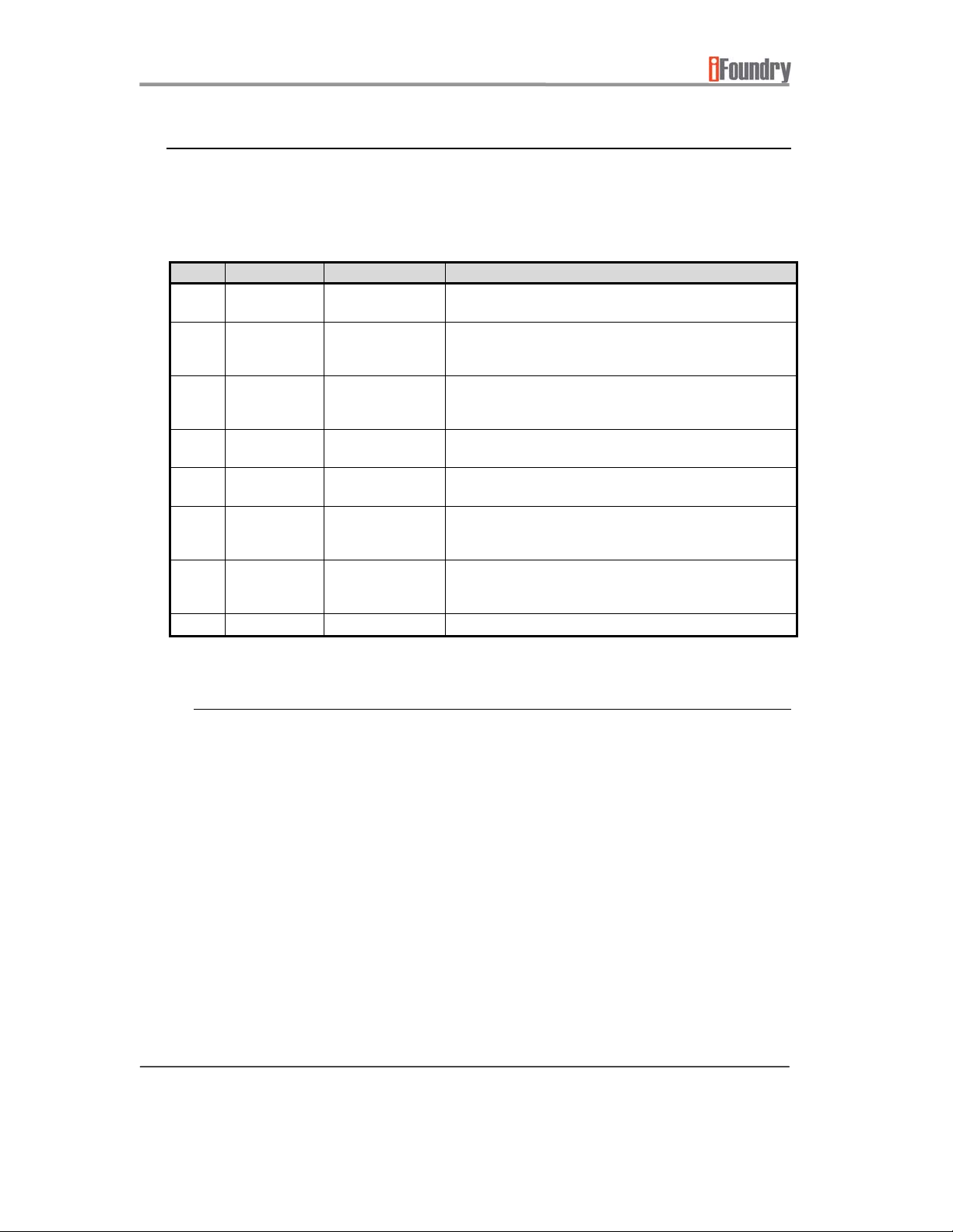
3.1 Connectors
Following is a list of connectors used on the board, and their respective functions. The
connectors may in later sections be referred to by either name or reference designation.
Refer to the board diagram on the previous page for connector and component locations.
REF NAME / TYPE CONNECTED TO DESCRIPTION / PURPOSE
RJ1 RJ45
connector
JTAG JTAG 14-pin
connector
SD1 SD Memory
Card
connector
P1 DB9M MSP430 UART2 Used as a generic port or connected to an external
P2 DB9M MSP430 UART1 Used as a generic port or connected to an Oximeter for
P3 DB9M IFSYS-5043
USB1 Mini USB MSP430 UART3 Primary function is to provide power to the IFSYS-5651.
CSR development
tools.
JTAG debugger
for software
development
Accepts SD
memory cards
UART
Firmware download port for IFSYS-5043 Bluetooth module
Used with MSP430 development environment..
Provide storage for developer’s applications.
Bluetooth module for MSP430 applications.
MSP430 applications.
Connects IFSYS-5043 to an external host or to an Oximeter
for IFSYS-5043 applications. If IFSYS-5043 module is
connected to the MSP430, this port is unused/unconnected.
The miniUSB serves two different modes, controlled by
MODE jumper (details in Jumpers section)
3.1.1 MSP430 UART hardware limitations
The developer of MSP430 applications is advised about the limitations with regards to
the MSP430 serial communications. MSP430 provides a basic 3-wire UART
communication. For applications that require hardware based (RTS/CTS) flow control,
this capability is simulated by MSP430 GPIO lines.
It should be noted that simulated hardware flow control incurs processor cycles, and
the developer should decide between implementing simulated hardware flow control,
or use software based flow control schemes.
All UART ports of the MSP430 are of the 3-wire type. Please refer to the schematics
for the IFSYS-5651 MSP430 Bluetooth Development Board for details on which GPIO
pins are allocated for UART flow control purposes.
Page 8 of 50
Copyright © 2008 iFoundry Systems
Page 9
IFSYS-5651 MSP430 Bluetooth Evaluation Kit User Guide
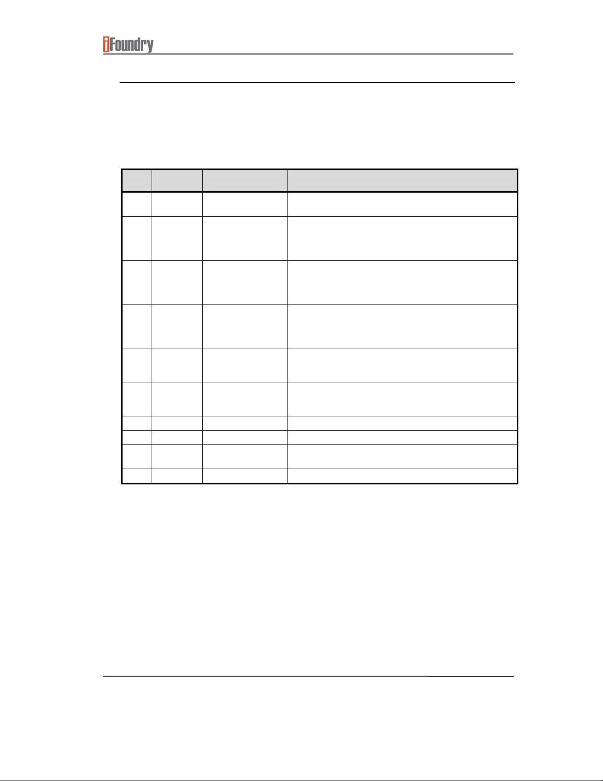
3.2 Switches & LEDs
Following is a list of switches and LEDs used on the board, and their respective functions.
The components may in later sections be referred to by either name or reference
designation. Refer to the board diagram on the previous page when locating these
components.
REF NAME /
TYPE
RST RST
button
S1 Button 1 MSP430 (P2-4) /
S2 Button 2 MSP430 (P2-5) /
S3 Button 3 MSP430 (P2-6) /
LED1 Red LED MSP430 (P4-0) /
LED2 Yellow
LED
LED3 Green LED MSP430 (P4-2) General use – driven by MSP430 GPIO pin
LED4 Blue LED MSP430 (P4-3) General use – driven by MSP430 GPIO pin
PWR LED5
(Green)
CONNECTED TO DESCRIPTION / PURPOSE
Board reset Performs a hardware reset to the IFSYS-5651 board (MSP430
and IFSYS-5043)
Button is connected to both the MSP430 microcontroller and
IFSYS-5043 (PIO7)
IFSYS-5043 (PIO4)
IFSYS-5043 (PIO5)
IFSYS-5043 (PIO2)
MSP430 (P4-1) /
IFSYS-5043 (PIO3)
Power supply Power LED - Indicates IFSYS-5651 board is powered on when
IFSYS-5043 Bluetooth Module, and should be sensed by only
one application at any time (either running on MSP430 or
IFSYS-5043)
Button is connected to both the MSP430 microcontroller and
IFSYS-5043 Bluetooth Module, and should be sensed by only
one application at any time (either running on MSP430 or
IFSYS-5043)
Button is connected to both the MSP430 microcontroller and
IFSYS-5043 Bluetooth Module, and should be sensed by only
one application at any time (either running on MSP430 or
IFSYS-5043)
General use – driven by either MSP430 GPIO pin or IFSYS5043 (in stand-alone mode). LEDSEL jumper selects between
MSP430 and IFSYS-5043.
General use – driven by either MSP430 GPIO pin or IFSYS5043 (in stand-alone mode). LEDSEL jumper selects between
MSP430 and IFSYS-5043.
lit
Page 9 of 50Copyright © 2008 iFoundry Systems
Page 10
IFSYS-5651 MSP430 Bluetooth Evaluation Kit User Guide
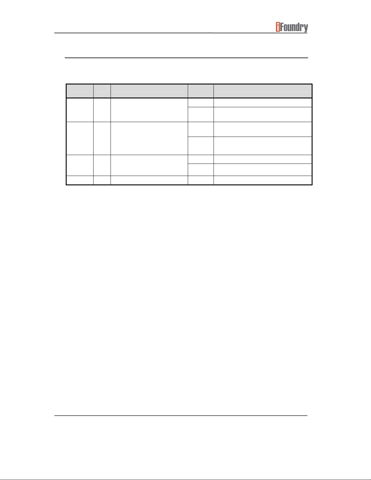
3.3 Jumpers
Following is a list of jumpers used on the board, and their respective functions.
NAME REF PURPOSE JUMPE
MODE W28 Sets MSP430 to normal
5043
CONN
LEDSEL W18 Determines if LED1 & LED2 are
operating mode or firmware
download mode
W21 Determines if IFSYS-5043 is
connected to RS232 at P3
(stand-alone mode), or to
MSP430 (MSP430 hosted
mode)
driven by MSP430 or IFSYS5043 in stand-alone mode
R ON
1-2 NORM – Normal MSP430 operating mode
2-3 FWDL – MSP430 firmware download
1-2 INT – IFSYS-5043 is connected to UART0
2-3 EXT – IFSYS-5043 is connected to RS232
1-2 MSP430 – LEDs controlled by MSP430
2-3 5043 – LEDs controlled by IFSYS-5043
SETTING / DESCRIPTION
mode
of MSP430
connector P3
Page 10 of 50
Copyright © 2008 iFoundry Systems
Page 11
IFSYS-5651 MSP430 Bluetooth Evaluation Kit User Guide
3.4 Modules / Components
The table below shows other important items related to the IFSYS-5651 board.
MODULE /
COMPONENT
NAME
RJ45 cable Programming cable used to programming the IFSYS-5043
IFSYS-5043 iFoundry Bluetooth Module (can be operated as an HCI
Prototyping area For prototyping external circuitry -na-
DESCRIPTION / PURPOSE CONNECTS TO
Between PC and the
module
module, or stand-alone module)
IFSYS-5043 module via
connector RJ1
MSP430, or external
host such as a PC
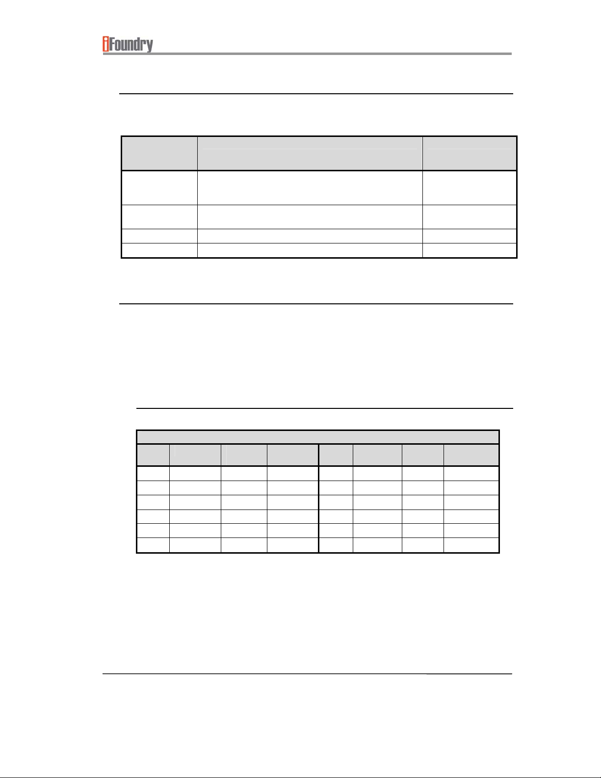
3.5 MSP430 General Purpose I/O (GPIO) signals
Following is a list of MSP430 GPIOs which are not tied to specific board functions and can
be freely designated for any purpose. The components may in later sections be referred
to by either name or reference designation. It may be helpful to reference the board
diagram on the previous page when locating these components. In the following sections,
the term “-nc-“ means “not connected”.
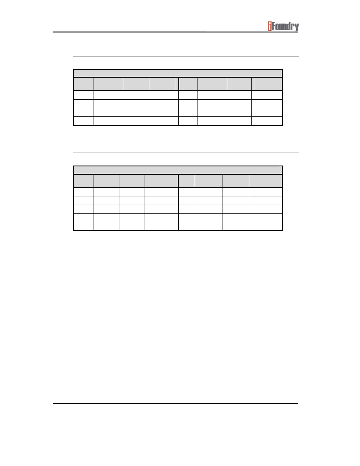
3.5.1 JP1 Header Signals
JP1 HEADER SIGNALS
PIN SIGNAL MSP430
PIN
1 PIO-6-0 97 P6-0 2 PIO-6-1 98 P6-1
3 PIO-6-2 99 P6-2 4 PIO-6-3 100 P6-3
5 PIO-6-4 1 P6-4 6 PIO-6-5 2 P6-5
7 PIO-6-6 3 P6-6 8 PIO-6-7 4 P6-7
9 PIO-7-4 5 P7-4 10 PIO-7-5 6 P7-5
11 PIO-7-6 7 P7-6 12 PIO-7-7 8 P7-7
MSP430
PIN NAME
PIN SIGNAL MSP430
PIN
MSP430
PIN NAME
Page 11 of 50Copyright © 2008 iFoundry Systems
Page 12
IFSYS-5651 MSP430 Bluetooth Evaluation Kit User Guide
3.5.2 JP2 Header Signals
JP2 HEADER SIGNALS
PIN SIGNAL MSP430
PIN
1 PIO-7-2 55 P7-2 2 PIO-7-3 56 P7-3
3 PIO-4-6 49 P4-6 4 PIO-4-7 50 P4-7
5 PIO-4-4 47 P4-4 6 PIO-4-5 48 P4-5
7 PIO-3-7 42 P3-7 8 -nc- -nc- -nc-
MSP430
PIN NAME
PIN SIGNAL MSP430
3.5.3 JP3 Header Signals
JP3 HEADER SIGNALS
PIN SIGNAL MSP430
PIN
1 PIO-2-2 27 P2-2 2 PIO-2-3 28 P2-3
3 PIO-2-0 25 P2-0 4 PIO-2-1 26 P2-1
5 PIO-1-6 23 P1-6 6 PIO-1-7 24 P1-7
7 PIO-1-4 21 P1-4 8 PIO-1-5 22 P1-5
9 PIO-1-0 17 P1-0 10 PIO-1-3 20 P1-3
MSP430
PIN NAME
PIN SIGNAL MSP430
PIN
PIN
MSP430
PIN NAME
MSP430
PIN NAME
Page 12 of 50
Copyright © 2008 iFoundry Systems
Page 13
IFSYS-5651 MSP430 Bluetooth Evaluation Kit User Guide
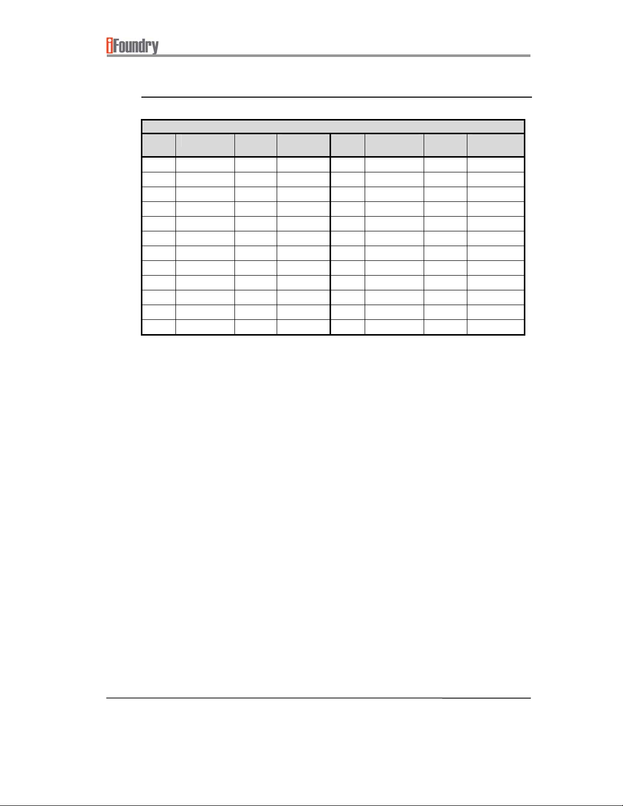
3.5.4 JP5 Header Signals
JP5 HEADER SIGNALS
PIN SIGNAL MSP430
PIN
1 PIO-11-0 84 P11-0 2 PIO-11-1 85 P11-1
3 PIO-11-2 86 P11-2 4 -nc- -nc- -nc5 PIO-10-6 82 P10-6 6 PIO-10-7 83 P10-7
7 PIO-10-2 78 P10-2 8 PIO-10-3 79 P10-3
9 PIO-10-0 76 P10-0 10 PIO-10-1 77 P10-1
11 PIO-9-6 74 P9-6 12 PIO-9-7 75 P9-7
13 PIO-9-2 70 P9-2 14 PIO-9-3 71 P9-3
15 PIO-9-0 68 P9-0 16 PIO-9-1 69 P9-1
17 PIO-8-6 66 P8-6 18 PIO-8-7 67 P8-7
19 PIO-8-4 61 P8-4 20 PIO-8-5 65 P8-5
21 PIO-8-2 59 P8-2 22 PIO-8-3 60 P8-3
23 PIO-8-0 57 P8-0 24 PIO-8-1 58 P8-1
MSP430
PIN NAME
PIN SIGNAL MSP430
PIN
MSP430
PIN NAME
Page 13 of 50Copyright © 2008 iFoundry Systems
Page 14
IFSYS-5651 MSP430 Bluetooth Evaluation Kit User Guide
3.6 IFSYS-5043 Module General Purpose I/O (GPIO) signals
Following is a list of MSP430 GPIOs which are not tied to specific board functions and can
be freely designated for any purpose. The components may in later sections be referred
to by either name or reference designation. It may be helpful to reference the board
diagram on the previous page when locating these components.
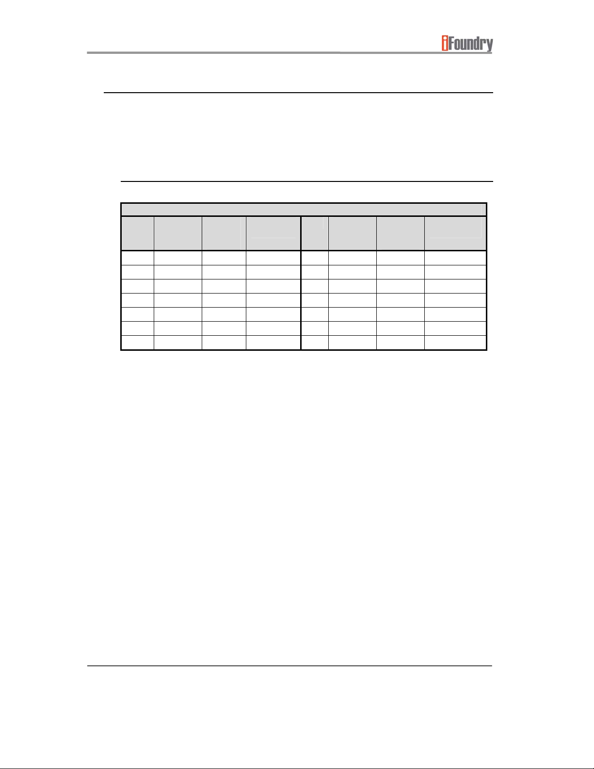
3.6.1 JP4 Header Signals
JP4 HEADER SIGNALS
PIN SIGNAL IFSYS-
5043
PIN
1 BT-PIO-0 2 PIO0 2 BT-PIO-1 49 PIO1
3 BT-PIO-8 48 PIO8 4 BT-PIO-9 47 PIO9
5 BT-PIO-10 46 PIO10 6 BT-PIO-11 45 PIO11
7 BT-AIO-0 13 AIO0 8 BT-AIO-1 14 AIO1
9 BT-AIO-3 15 AIO3 10 -nc- -nc- -nc11 BT-TXD 24 UART_TX 12 BT-RXD 22 UART_RX
13 BT-RTS# 23 UART_RTS 14 BT-CTS# 20 UART_CTS
IFSYS-5043
PIN NAME
PIN SIGNAL IFSYS-
5043
PIN
IFSYS-5043
PIN NAME
Page 14 of 50
Copyright © 2008 iFoundry Systems
Page 15

IFSYS-5651 MSP430 Bluetooth Evaluation Kit User Guide
4 PREPARING IFSYS-5651 FOR USE
This section explains how to set up the IFSYS-5651 Development Board
4.1 Downloading the IFSYS-5651 board software package
In order to use the IFSYS-5651 Development Board, you will need to install software and
documentation that comes with it. This can be downloaded from iFoundry’s website from
the links provided in Section 12 - PRODUCT WEBSITE.
Uncompress the IFSYS-5651 package you downloaded on your PC. The package will be
stored under a top level folder called “IFSYS-5651”. All other folders will be referred from
this “home” folder location.
4.2 Preparing for installation
Prior to running any of the demo programs for the MSP430 please ensure that you have
installed the USB-to-Serial driver for the IFSYS-5651 board. Instructions for this is located
in Section 11 - INSTALLING THE USB-TO-SERIAL DRIVER.
Once you have done this, you should proceed to Section 5 - CONFIGURING IFSYS-
5651 FOR OPERATION.
4.3 Powering up the IFSYS-5651 board
The IFSYS-5651 board is powered up through the USB connector. This happens when
the board is normally connected to a PC or other host. Even if the PC is not involved in
the transfer of data, the USB cable will still be necessary, if only to supply power to the
IFSYS-5651 board.
Page 15 of 50Copyright © 2008 iFoundry Systems
Page 16

IFSYS-5651 MSP430 Bluetooth Evaluation Kit User Guide
5 CONFIGURING IFSYS-5651 FOR OPERATION
The IFSYS-5651 MSP430 Bluetooth Development board has versatile functionality, and can
operate in a number of different modes:
• it can be used to develop embedded Bluetooth applications based on both the
MSP430 and IFSYS-5043 Bluetooth Module,
• it can be used to develop Bluetooth applications based on the MSP430 and a
Bluetooth Module that is connected externally to one of the MSP430 UART ports
• it can be used to develop embedded applications for the MSP430 alone, or
• it can serve as a stand-alone Bluetooth development platform for the IFSYS-5043
Bluetooth Module.
• It can be used to develop application using the IFSYS-5043 as an HCI module alone.
This section details how to configure the IFSYS-5651 board to operate in any of these modes,
as well as configure the board to support firmware download operations to either the MSP430
or IFSYS-5043 module.
5.1 Configuring for MSP430 and IFSYS-5043 development
This is the configuration for developing MSP430 applications which make use of the onboard IFSYS-5043 Bluetooth module based on CSR’s BC03 single chip radio.
5.2 Configuring for MSP430 stand-alone development
This is the configuration for developing MSP430 applications that do not make use of the
on-board IFSYS-5043 Bluetooth module.
5.3 Configuring for MSP430 and external Bluetooth module development
This configuration supports MSP430 Bluetooth development which makes use of an
external Bluetooth module attached to the RS232 port at P1 of the IFSYS-5651 board. In
this configuration, the Bluetooth module must be configured to use 3 wired HCI interface
mode.
5.4 Configuring for IFSYS-5043 for external hosted development
In this mode, the IFSYS-5043 Bluetooth module is connected to an external host, such as
a PC or other similar device running a Bluetooth stack. The IFSYS-5043 operates as an
HCI UART device in this case.
Page 16 of 50
Copyright © 2008 iFoundry Systems
Page 17

IFSYS-5651 MSP430 Bluetooth Evaluation Kit User Guide
5.5 Configuring for IFSYS-5043 stand-alone development
In this mode, the IFSYS-5043 Bluetooth module operates as a stand-alone module, with
the Bluetooth stack as well as application residing wholly on the IFSYS-5043 module
itself.
5.6 Downloading firmware to the MSP430
This mode is used for downloading applications to the MSP430. Applications can be
sample applications that are provided by iFoundry, or those that you develop for the
IFSYS-5651 board.
5.7 Downloading firmware to the IFSYS-5043 Bluetooth Module
This mode is used for downloading code to the IFSYS-5043.
Page 17 of 50Copyright © 2008 iFoundry Systems
Page 18

IFSYS-5651 MSP430 Bluetooth Evaluation Kit User Guide
6 SETTING UP IFSYS-5651 FOR MSP430 SOFTWARE DEVELOPMENT
This section shows you how the IFSYS-5651 can be set up for developing MSP430
applications.
6.1 Development tools & environment
Development of stand-alone applications for the IFSYS-5043 module requires the
following tools:
• Development tools for compiling and debugging software. The IFSYS-5651 supports
generic JTAG development environments, which include:
• IAR Embedded Workbench 5.0 or later
• TI Code Composer Studio
• JTAG debugger such as Texas Instruments MSP-FET U430F debugger, or other
similar device.
Embedded Workbench is available from IAR Systems at www.iar.com. Code Composer
Studio is available from Texas Instruments Incorporated at www.ti.com.
The diagram below shows the key components related to setting up the IFSYS-5651
board for MSP430 development.
Page 18 of 50
Copyright © 2008 iFoundry Systems
Page 19

IFSYS-5651 MSP430 Bluetooth Evaluation Kit User Guide
6.2 Configuration for MSP430 software development
Connect up the IFSYS-5651 Development Board as follows:
• Connect the USB cable provided with your evaluation kit between the miniUSB port of
the IFSYS-5651 and a USB port on the PC. This is primarily to supply power to the
IFSYS-5651 board. It is recommended that the developer should have installed the
USB -to-Serial driver for this board previously. Instructions for this can be found in
Section 11 - INSTALLING THE USB-TO-SERIAL DRIVER.
• Ensure that the IFSYS-5651 board is not configured in firmware download mode
• Ensure that the IFSYS-5651 peripherals are configured appropriately.
6.3 Board configuration/Jumper settings
Connect up the IFSYS-5651 Development Board as follows:
• Prior to connecting up the board, ensure that the following jumper settings are in
place:
• MODE jumper – this should be set to NORM position (installed on pins 1-2)
• 5043CONN jumper – should be set to INT (installed on pins 1-2). This makes
available Bluetooth connectivity to your application.
• LEDSEL – should be set to MSP430 (installed on pins 1-2), to enable MSP430 to
control LEDs.
• Attach the JTAG debugger to the JTAG port on the IFSYS-5651 board, ensuring that
the JTAG debugger is not powered on (ie plug into the PC’s USB port),
• Next connect the USB cable to a PC. Power up the PC, if not already on.
• Now connect the JTAG debugger to the PC’s USB port, and start up your
development environment.
Page 19 of 50Copyright © 2008 iFoundry Systems
Page 20

IFSYS-5651 MSP430 Bluetooth Evaluation Kit User Guide
At this point, the development configuration should look similar to the one shown in the
diagram below.
Page 20 of 50
Copyright © 2008 iFoundry Systems
Page 21

IFSYS-5651 MSP430 Bluetooth Evaluation Kit User Guide
7 SETTING UP IFSYS-5043 AS AN HCI BLUETOOTH MODULE
This section shows you how the IFSYS-5043 can be set up as a generic HCI module for
connection to a host controller such as the on-board MSP430, an external PC or other similar
device. In this case, the host is likely to be running a Bluetooth stack as well as applications
on top of that.
7.1 Preparations
Key components related to setting up for hosted IFSYS-5043 development are shown in
the diagram below.
Page 21 of 50Copyright © 2008 iFoundry Systems
Page 22

IFSYS-5651 MSP430 Bluetooth Evaluation Kit User Guide
Prior to connecting anything up or powering on the IFSYS-5651 board, ensure the
following procedures have been carried out:
• Configure jumpers as follows:
• 5043CONN jumper is set to EXT (installed on pins 2-3) – this connects the
IFSYS-5043 to the RS232 at P3 instead of MSP430 microcontroller
• LEDSEL jumper is set to 5043 position (installed on pins 2-3)
• MODE jumper is set to NORM position (installed on pins 1-2)
• Ensure that you have HCI firmware loaded into the IFSYS-5043 module. For the
firmware download procedure, refer to Section 9.4 - Restoring HCI UART firmware
to IFSYS-5043.
7.2 Serial cable configuration
The RS232 connector at P3 of the IFSYS-5651 board is used by the IFSYS-5043
Bluetooth module to connect to the host. P3 connector is a DB9(Male) connector with the
same pinout as the COM port connector on a PC. When connecting to a PC COM port,
use a null modem (crossed) DB9(Female)-to-DB9(Female) cabl e.
Page 22 of 50
Copyright © 2008 iFoundry Systems
Page 23

IFSYS-5651 MSP430 Bluetooth Evaluation Kit User Guide
7.3 Configuration for IFSYS-5043 hosted development
Connect up the IFSYS-5651 development board to the PC using a serial RS232 cable
and the USB cable, as shown below.
7.4 Default IFSYS-5043 Configuration
The IFSYS-5043 is shipped as a Bluetooth HCI module configured for 3-wire UART
interface based on Bluetooth SIG’s H3W specification. The H3W interface is set at
9600bps data rate.
Page 23 of 50Copyright © 2008 iFoundry Systems
Page 24

IFSYS-5651 MSP430 Bluetooth Evaluation Kit User Guide
8 SETTING UP IFSYS-5043 FOR STAND-ALONE DEVELOPMENT
This section shows you how the IFSYS-5043 can be set up for stand-alone development in
which the IFSYS-5043 module hosts all the Bluetooth firmware and the applications you
develop for it within the module itself.
CAUTION
The IFSYS-5053 Bluetooth module comes loaded with HCI Bluetooth firmware. It
is strongly recommended that you first save this firmware in case you need to
restore it at a future date. Bluetooth addresses are unique to each module and
you should note the specific IFSYS-5651 board that the saved firmware belongs
to. For instructions on how to save the HCI firmware on a IFSYS-5043 module,
please follow the instructions listed in Section 9.2 - Backing-up original IFSYS-
5043 firmware.
8.1 Development tools & environment
Development of stand-alone applications for the IFSYS-5043 module requires the
following tools:
• CSR BlueLab V3.6.2 or later,
• CSR BlueSuite 1.24 or later (contains PSTools for configuring the operation of the
Bluetooth radio, and BlueFlash for downloading firmware to IFSYS-5043 module)
• Windows PC to host the development environment,
• Programming Cable for IFSYS-5043 Bluetooth Module (Part number MECB02061)
(supplied as part of the Evaluation Kit).
With the exception of the Programming Cable for IFSYS-5043 Bluetooth Module, these
tools are available under license from Cambridge Silicon Radio. It is assumed that the
developer has access to these tools in order to develop stand-alone applications for the
IFSYS-5043 Bluetooth module. CSR can be contacted at www.csr.com.
Page 24 of 50
Copyright © 2008 iFoundry Systems
Page 25

IFSYS-5651 MSP430 Bluetooth Evaluation Kit User Guide
8.2 Preparations
Key components related to setting up for stand-alone IFSYS-5043 Bluetooth development
are shown in the diagram below.
In Standalone mode, the IFSYS-5043 module is able to make use of the following
resources:
• LEDs - LED1 and LED2
• Buttons – S1, S2 and S3. The RST button performs a hardware reset of the IFSYS-
5043 module.
Page 25 of 50Copyright © 2008 iFoundry Systems
Page 26

IFSYS-5651 MSP430 Bluetooth Evaluation Kit User Guide
Prior to connecting anything up or powering on the IFSYS-5651 board, ensure the
following procedures have been carried out:
• Configure jumpers as follows:
• 5043CONN jumper is set to EXT (installed on pins 2-3) – this connects the
IFSYS-5043 to the RS232 at P3 instead of MSP430 microcontroller
• LEDSEL jumper is set to 5043 position (installed on pins 2-3) – this allows LED1
and LED2 to be controlled by the IFSYS-5043,
• MODE jumper is set to NORM position (installed on pins 1-2)
• As part of program development, you will need to eventually download your code to
the IFSYS-5043 module. Section 9 - DOWNLOADING FIRMWARE TO IFSYS-5043
BLUETOOTH MODULE describes the procedure for doing this.
Page 26 of 50
Copyright © 2008 iFoundry Systems
Page 27

IFSYS-5651 MSP430 Bluetooth Evaluation Kit User Guide
8.3 Configuration
Once you have configured the jumpers on the IFSYS-5651 board, you can connect the
board to the PC as follows:
8.4 IFSYS-5043 Program Development
Once you have developed your application, follow the procedure in Section 9 -
DOWNLOADING FIRMWARE TO IFSYS-5043 BLUETOOTH MODULE to download
your firmware into the IFSYS-5043 module.
If for any reason you need to reload the original HCI firmware into the IFSYS-5043, follow
the procedure described in Section 9.4 - Restoring HCI UART firmware to IFSYS-5043.
Note that standalone IFSYS-5043 applications can access an external RS232 peripheral
attached to P3 connector.
Page 27 of 50Copyright © 2008 iFoundry Systems
Page 28

IFSYS-5651 MSP430 Bluetooth Evaluation Kit User Guide
9 DOWNLOADING FIRMWARE TO IFSYS-5043 BLUETOOTH MODULE
This section describes the procedure for downloading firmware to the IFSYS-5043 Bluetooth
module. The reader is also encouraged to understand the program ming environment for
developing applications for the IFSYS-5043 Bluetooth module.
9.1 Preparations for firmware download to IFSYS-5043
Prior to downloading firmware, please ensure that the following items are available:
• A PC or laptop with a parallel port
• IFSYS-5651 Development Board
• Programming Cable for IFSYS-5043 Bluetooth Module (Part number MECB02061)
(supplied as part of the Evaluation Kit)
• USB cable (supplied as part of the Evaluation Kit)
The board should be connected to the PC as indicated below:
• Programming Cable for IFSYS-5043 should be connected to the RJ45 on the IFSYS-
5651 and the other end to the PC’s Parallel port.
• USB cable should be connected miniUSB end to the miniUSB connector on the
IFSYS-5651 board, the other end to a USB port on your PC.
Page 28 of 50
Copyright © 2008 iFoundry Systems
Page 29

IFSYS-5651 MSP430 Bluetooth Evaluation Kit User Guide
9.2 Backing-up original IFSYS-5043 firmware
Before doing any firmware modification of the IFSYS-5043 module firmware, it is strongly
encouraged to keep a backup of the original firmware as the original firmware contains a
known working condition of IFSYS-5043 in HCI mode. It is also because the IFSYS-5043
module on your IFSYS-5651 contains a unique Bluetooth Address and crystal frequency
trim value trimmed to the IFSYS-5043 on your IFSYS-5651 board.
This section describes the procedure to back up IFSYS-5043 firmware. Do note that the
following procedures is based on one version of CSR software and this may change at
CSR’s discretion.
Run CSR BlueFlash, and
the following screen will
appear
Next, click on Dump, select the file
location, and specify the filename, and
click on Save.
Click on Stop Processor, and the
following screen will appear.
Page 29 of 50Copyright © 2008 iFoundry Systems
Page 30

IFSYS-5651 MSP430 Bluetooth Evaluation Kit User Guide
The following screen indicates progress of the backup process.
When backup is successfully completed, the following screen will appear.
At this point you should have two files of the same name with two different
extensions, .xdv and .xpv. You should keep these files in a safe place, and relate
the files to the specific board. In the event that you want to restore these files, you
should restore them to the same board that you saved them from.
Page 30 of 50
Copyright © 2008 iFoundry Systems
Page 31

IFSYS-5651 MSP430 Bluetooth Evaluation Kit User Guide
9.3 Procedure for downloading firmware to IFSYS-5043 module
This section explains the procedure for downloading firmware to the IFSYS-5043 module
using BlueFlash. However, during the firmware development process, firmware download
is done via BlueLab as part of the debugging process.
Run CSR BlueFlash, and the following screen will appear
Click on Choose File, locate and select the firmware you want to download to the IFSYS5043 module. If you are restoring the “as shipped” firmware to an IFSYS-5651 board, you
should select the files you originally saved in the previous section.
Page 31 of 50Copyright © 2008 iFoundry Systems
Page 32

IFSYS-5651 MSP430 Bluetooth Evaluation Kit User Guide
After the file has been selected, click on Stop Processor.
Next, click on Download to proceed with the download process.
The following screen shows that download process has been completed succes sfully.
Page 32 of 50
Copyright © 2008 iFoundry Systems
Page 33

IFSYS-5651 MSP430 Bluetooth Evaluation Kit User Guide
9.4 Restoring HCI UART firmware to IFSYS-5043
In the event that you would like to restore the IFSYS-5043 with the original firmware that
shipped with it, follow the procedure in the last section, to download firmware that you
originally saved.
Page 33 of 50Copyright © 2008 iFoundry Systems
Page 34

IFSYS-5651 MSP430 Bluetooth Evaluation Kit User Guide
10 DOWNLOADING FIRMWARE TO MSP430 MICROCONTROLLER
There are two ways in which firmware can be downloaded to the MSP430 microcontroller. If
you are using commercial development tools such IAR Embedded Workbench or TI Code
Composer Studio, you should use the JTAG firmware download features that are built into
these tools. To download code using this approach, please refer to the documentation
provided by the manufacturer of your development tools.
If you are not using these tools, and simply want to try out the sample/demo applications
provided by iFoundry, you can use the procedure outlined in the following sections. This
downloading method uses the UART port provided through the miniUSB connector on the
IFSYS-5651 board, and obviates the requirement for JTAG based tools. This approach uses a
software download utility provided by iFoundry.
For complete instructions on using this utility to download firmware to the MSP430, please
refer to the document MSP430 Flash Utility User Guide.
Page 34 of 50
Copyright © 2008 iFoundry Systems
Page 35

IFSYS-5651 MSP430 Bluetooth Evaluation Kit User Guide
11 INSTALLING THE USB-TO-SERIAL DRIVER
IFSYS-5651 uses an on-board USB-to-Serial converter from Silicon Labs based on the
CP210x device. In order for the IFSYS-5651 port to appear as a virtual COM port on your
computer, you need to install the USB-serial driver. This section details the driver installation
procedure.
CAUTION
Driver installation should be performed WITHOUT the IFSYS-5651
board attached to the USB port, and be performed BEFORE the
board is plugged in for the first time.
To install the USB-to-Serial driver, locate the file called
“CP210x_VCP_Win2K_XP_S2K3.exe”. This is located in the \ifsys-
5651\msp430\CP210x\Vx.y folder, where x.y indicates the version numbe r of the driver.
Page 35 of 50Copyright © 2008 iFoundry Systems
Page 36

IFSYS-5651 MSP430 Bluetooth Evaluation Kit User Guide
When you have located the file, double click on it to start the installation process. The
following screen will appear.
Press Next to proceed.
You will then see the following license agreement screen:
Press Yes to accept the license agreement.
Page 36 of 50
Copyright © 2008 iFoundry Systems
Page 37

The following screen will then appear:
IFSYS-5651 MSP430 Bluetooth Evaluation Kit User Guide
If you accept the default location
recommended by the software in which to
install the driver, press Next to proceed to
the screen following the next.
Otherwise, to change the install location
press Browse, which will display the
screen shown on the right.
Select the folder you prefer to have the
driver installed in, and press OK.
Page 37 of 50Copyright © 2008 iFoundry Systems
Page 38

IFSYS-5651 MSP430 Bluetooth Evaluation Kit User Guide
The selected folder will now be displayed on screen. Press Next to proceed.
Driver installation will start at this point, with the progress indication displayed on the
screen below. Typically this process should take only a few seconds.
Page 38 of 50
Copyright © 2008 iFoundry Systems
Page 39

IFSYS-5651 MSP430 Bluetooth Evaluation Kit User Guide
Once the driver has been installed, you will see the following screen.
At this point, driver installation has been completed. Press Finish to exit the program.
Now you are ready to physically attach the IFSYS-5651 board to the USB port on your
computer.
Page 39 of 50Copyright © 2008 iFoundry Systems
Page 40

IFSYS-5651 MSP430 Bluetooth Evaluation Kit User Guide
11.1 Attaching the IFSYS-5651 to your computer’s USB port
Before attaching the IFSYS-5651 board to the USB port, please note the important point
below.
CAUTION
In the event that you intend to attach two IFSYS-5651 boards to the
same computer (but on different USB ports), you should start off by
attaching only one. This step is important because you need to
record which virtual COM port the device appears at.
When you attach the first IFSYS-5651 board, Windows normally detects and recognizes
the board through its USB connection, and attempts to load the driver you installed in the
previous step.
If this is the first time you are attaching the IFSYS-5651 on a particular USB port,
Windows will prompt you with the following screen:
Select Yes, this time only and click on Next.
Page 40 of 50
Copyright © 2008 iFoundry Systems
Page 41

IFSYS-5651 MSP430 Bluetooth Evaluation Kit User Guide
You will be presented with the following screen:
Select Install the software automatically (Recommended) and click Next.
When the following screen appears, click on Finish.
Page 41 of 50Copyright © 2008 iFoundry Systems
Page 42

IFSYS-5651 MSP430 Bluetooth Evaluation Kit User Guide
You will then be presented with the following screen, which appears to be the same as the
one shown earlier. This is normal, as Windows needs to install the virtual COM ports now.
Press Next to continue to the following screen.
Select Install the software automatically (Recommended) and click Next.
Page 42 of 50
Copyright © 2008 iFoundry Systems
Page 43

IFSYS-5651 MSP430 Bluetooth Evaluation Kit User Guide
You should now reach the following screen, which indicates that the driver has been
activated for the USB-to-Serial device.
At this point, you should be able to use the IFSYS-5651 board.
CAUTION
Note that if you plug the IFSYS-5651 board into another USB port for
the first time, you might need to go through this section again.
Page 43 of 50Copyright © 2008 iFoundry Systems
Page 44

IFSYS-5651 MSP430 Bluetooth Evaluation Kit User Guide
11.2 Determining the virtual COM port
You can ascertain if the driver has been loaded by looking at the Windows Device
Manager entry. To do this, follow the steps below.
Right-click on the “My Computer” and select Properties from the choices to bring up the
System Properties screen below.
Select the Hardware tab in the System Properties dialog box. A screen like the one below
will appear.
Click on the Device Manager button.
Page 44 of 50
Copyright © 2008 iFoundry Systems
Page 45

IFSYS-5651 MSP430 Bluetooth Evaluation Kit User Guide
Clicking on Device Manager will bring up the following screen:
Look for the entry, under Ports (COM & LPT), that reads CP210x USB to UART Bridge
Controller (COMx). Make a note of the port indicated as COMx. You will need this
information later, to use with the IFSYS-5651 test program.
CAUTION
Note the “COMx” port that the adapter is installed on. This is the virtual COM port
driver that will be needed to run the some of the programs for the IFSYS-5651 board.
At this point, the environment has been configured for using the IFSYS-5651
Development Board.
Page 45 of 50Copyright © 2008 iFoundry Systems
Page 46

IFSYS-5651 MSP430 Bluetooth Evaluation Kit User Guide
11.3 Uninstalling or re-installing the software
If at some point you need to uninstall the software, or to re-install it, you should simply run
the driver installation software again. The software can intelligently detect if a previous
version has been installed in your system.
Upon re-invoking the driver installation software, the following screen will be displayed.
Select the desired choice by clicking once in the radio button on the dialog box above:
• Modify to change the program components,
• Repair to re-install all program components installed by the previous setup,
• Remove to uninstall the driver,
and click Next to proceed, or Cancel to exit the program without making changes.
CAUTION
If you are installing a new version over an older existing version, we would
recommend that you remove the earlier installation first, and then re-boot your
computer prior to installing the newer version, for best results.
Page 46 of 50
Copyright © 2008 iFoundry Systems
Page 47

IFSYS-5651 MSP430 Bluetooth Evaluation Kit User Guide
If you chose Remove, the following confirmation dialog box will pop up.
If you are sure, confirm your choice by clicking on the OK button.
Upon confirmation, the following screen will be displayed, showing progress indication of
the operation.
When the operation has been completed, the following screen will be displayed.
Press Finish to proceed.
Page 47 of 50Copyright © 2008 iFoundry Systems
Page 48

IFSYS-5651 MSP430 Bluetooth Evaluation Kit User Guide
12 PRODUCT WEBSITE
This section provides links to obtaining information and resources related to the IFSYS-5651
board.
12.1 IFSYS-5651 product website
Documentation, sample code, utilities and schematics for the IFSYS-5651 board can be
obtained from iFoundry’s website at the following link:
http://www.ifoundrysys.com/support_product.asp
Scroll down and click on the IFSYS-5651 MSP430 Bluetooth Evaluation Kit link to
proceed to the IFSYS-5651 product page.
12.2 Discussion Forum
iFoundry is hosting a discussion forum on the IFSYS-5651 product. To join the discussion
forums, please go to the IFSYS-5651 product website.
Page 48 of 50
Copyright © 2008 iFoundry Systems
Page 49

IFSYS-5651 MSP430 Bluetooth Evaluation Kit User Guide
13 SUPPORT
Should you run into any problems, you may contact iFoundry in any of the following ways:
• For technical support, please e-mail: support@ifoundrysys.com
• For sales support, please e-mail: sales@ifoundrysys.com
• iFoundry web site: www.ifoundrysys.com
As iFoundry continues to enhance our kits, please review our web site from time to time to
check for available updates.
14 ORDERING NUMBE RS
The IFSYS-5043 Bluetooth module is available from iFoundry in a variety of product
variations. The product or ordering code associated with the IFSYS-5043 Bluetooth HCI
module is IFSYS-5043:3103 Bluetooth HCI UART module.
The IFSYS-5651 Evaluation Kit may be ordered as IFSYS-5651:1101 MSP430 Bluetooth
Evaluation Kit.
Page 49 of 50Copyright © 2008 iFoundry Systems
Page 50

IFSYS-5651 MSP430 Bluetooth Evaluation Kit User Guide
This page intentionally left blank
Page 50 of 50
P/N: MDMA02060
Copyright © 2008 iFoundry Systems
 Loading...