


iFocus DVR Manual
For Model (Software version 1.04.021 onwards):
DVR8A+/ 16B+
DVR4/ 8/ 16E+
iFocus Pte Ltd


iFocus DVRA+/B+/E+ Manual Version 4.2
Copyright Statement
Copyright 1999-2008. Version 4.0 all rights reserved
No part of this publication may be reproduced, transmitted, transcribed, translated into any
language, or archive in a storage system in any form or by any means, mechanical, electronic,
magnetic, optical, chemical, manual or otherwise, without the prior written permission of
iFocus Pte Ltd.
Disclaimer Statement
iFocus Pte. Ltd. makes no representations or warranties, either expressed or implied, with
respect to the contents hereof and specifically disclaims any warranties, merchantability or
fitness for any particular purpose. The product and software mentioned in this user manual
are sold or licensed "as is". In the event of any incidental or consequential damages resulting
from any misuse or mishandling of the product, the buyer (and not iFocus Pte. Ltd.) assumes
the entire cost of all necessary servicing and repair. Furthermore, iFocus Pte. Ltd. reserves the
right to revise this user manual and to change from time to time in the contents hereof
without obligation to notify any person of such revision or changes.
In no event shall the manufacturer be liable for any consequential or incidental damages,
including any loss of business profits or any other commercial damages, arising out of use of
its products.

iFocus DVRA+/B+/E+ Manual Version 4.2
SAFETY INSTRUCTIONS
CAUTION: DANGER OF EXPLOSION IF BATTERY IS INCORRECTLY
REPLACED. REPLACE ONLY WITH THE SAME OR EQUIVALENT TYPE
RECOMMENDED BY THE MANUFACTURER. DISCARD USED BATTERIES
ACCORDING TO THE MANUFACTURER’S INSTRUCTIONS.
ATTENTION: IL Y A DANGER D’EXPLOSION S’IL Y A REMPLACEMENT
INCORRECT DE LA BATTERIE. REMPLACER UNIQUEMENT AVEC UNE
BATTERIE DU MÊME TYPE OU D’UN TYPE RECOMMENDÉ PAR LE
CONSTRUCTEUR. METTRE AU RÉBUT LES BATTERIES USAGÉES
CONFORMÉMENT AUX INSTRUCTIONS DU FABRICANT.
CAUTION: VENTILATION
Ensure unit’s operating temperature is 45°C or below for optimum performance. If unit is
kept in wooden/enclosed cabinet, ensure proper ventilation to protect from overheating. As a
guide, ensure that there is at least 4 inches space from the DVR to the cabinet walls. Ensure
the air temperature around the DVR is below 35 degree Celsius. Provide additional fan to
maintain good airflow around the DVR if necessary.
NOTICE: Minimum PC Specifications for iFocus DVR remote dial in function
Please note that for remote dial in to iFocus DVR either through modem/LAN or Internet, the
following minimum PC specifications would be required.
Intel Pentium IV 1.7GHz
256MB RAM
20 GB hard disk
1GB free space at least
MS Windows XP / 2000 / NT Server Professional OS
MS Office
MS Internet Explorer Version 6 and above
CD-ROM drive
Graphic display setting at 1024X768 pixels with at least 16 bits color
The remote dial in might not work properly for PCs with the following systems:
MS Windows ME / 98_SE OS or older
AMD CPU
[Note: Please select Intel P3 Compatible CPU when prompted by the PC
This will supersede other minimum PC specification.]
[Note: Contents are subjected to change without prior notice]

iFocus DVRA+/B+/E+ Manual Version 4.2
TABLE OF CONTENTS
1. Introduction 1
2. Model Convention 2
3. DVR Main Features and Specifications 3
3.1 8A+/ 16B+ Model Main Features and Specification 3
3.1.1 Features 3
3.2.2 Specifications 3
3.2 E+ Model Main Features and Specifications 4
3.2.1 Features 4
3.2.2 Specifications 4
4. DVR Configurations 5
5. DVR Connections 6
5.1 Camera and Monitor Connections 6
5.2 External IR Receiver Connections 7
5.3 Audio Camera Source and Speaker 7
5.3.1 Hardware Setup 7
5.3.2 Connection instruction (Example for Channel 1 recording) 8
5.4 External Alarm Input Connection 8
5.5 Alarm Output Connection and Disable Alarm 8
5.5 Clear Alarm using External Trigger 8
6. IR Remote Control 10
7. Power Up of DVR 11
7.1 AC Power Input Selector 11
7.2 Power Up of DVR 11
8. Full Screen Live View and DVR Log-in 12
8.1 Full Screen Live View 12
8.2 Digital Zoom 12
8.3 Status Bar Display 12
8.4 Hiding of Camera Name 12
8.5 Password Login 13
9. Camera View Settings 14
9.1 View Mode 14
9.2 Spot Monitor Out (For DVRE+ models only) 14
9.3 Camera Display Properties 15
9.4 Camera Settings 16
9.4.1 Set Camera Name 16
9.4.2 Turn on or off camera view 16
9.4.3 Turn on or off Camera SAE function 17
10. Setup Menu 18
10.1 Date/Time and Time Zone Setting 18
10.2 Password Change 18
10.3 Storage Option 18

iFocus DVRA+/B+/E+ Manual Version 4.2
10.4 Communication 19
10.4.1 Modem Rings 19
10.4.2 TEL 19
10.4.3 Dial-out IP 19
10.4.4 Server IP 19
10.4.5 Server Port 19
10.4.6 DVR ID 19
10.4.7 PTZ, modem and matrix switch 19
10.4.8 Network Setting 20
10.5 Key Lock 21
10.6 Re-Init 21
10.7 Archive to Optical Disc (For DVR with CD/ DVD-RW option only) 21
11. Record Menu 23
11.1 Record Info 23
11.2 Record Mode 23
11.3 Frame Rate and Audio Record Setting 24
11.3.1 Frame Rate and Record Mode 24
11.3.2 Audio Record Setting 24
11.4 Record Schedule 24
11.5 Manual Recording 25
11.6 Trigger Recording 25
11.7 Timer Recording 25
11.7.1 Timer Setting 25
11.7.2 Holiday Setting 26
11.8 Record Quality 26
12. Trigger Settings 27
12.1 External Trigger 27
12.2 Motion Trigger 28
12.2.1 Motion Grid Setting 28
12.2.2 Motion Sensitivity 29
12.2.3 System Trigger Delay Setting 29
12.3 Email Alert 29
13. Playback 30
13.1 Event Playback 30
13.2 Date/Time Playback 31
13.3 Playback Screen Setting 31
13.4 Playback Control Function 31
13.5 Camera Source Setting 32
13.6 Full Screen Playback 32
13.7 Playback with IFS Player 32
13.7.1 Installing IFS Player 32
13.7.2 Getting Started with IFS Player 34
14. Modem Dial In Basic Setup 35
14.1 Installing Setup Program for Modem Dial In 35
14.1.1 Installing RAS DVR Dialer Application Software 35
14.1.2 Setting up The RAS DVR Dialer 36
14.2 Modem Dial-in Setting 38
14.3 Configuration of the RAS DVR Dialer for Dialing 38
15. Pan/Tilt/Zoom Control 38

iFocus DVRA+/B+/E+ Manual Version 4.2
Appendix: DVR Full Menu Chart 38
1. Main and second level menu 38
2. Record, playback and trigger menu 38
3. Setup menu 38
Figures
Figure 1: DVR Full Configuration 5
Figure 2: Connection, External VGA Cable for DVR16+ 7
Figure 3: Connection, External VGA Cable for DVR8A+, 16B+, 4E+ and 8E+ 7
Figure 4: Connection, Monitors and Camera Sources 6
Figure 5: Connection, External IR 8
Figure 6: Mono to Stereo Splitter 8
Figure 7: Connection, Audio Feature 8
Figure 8: Connection, External Alarm Input 9
Figure 9: Connection, Alarm Output 9
Figure 10: Menu, Clear Alarm using External Trigger 2 9
Figure 11: Connection, Clear Alarm using External Trigger 10
Figure 12: IR Remote Control 11
Figure 13: Full-screen Live View Options 13
Figure 14: System Status Bar 12
Figure 15: Menu, Camera View Setting 14
Figure 16: Menu, Spot TV Out (Fix Mode) 14
Figure 17: Menu, Spot TV Out (Sep Mode) 15
Figure 18: Menu, Spot TV Out (Trig Mode) 15
Figure 19: Menu, Camera Display Properties 16
Figure 20: Menu, Setup 18
Figure 21: Menu, Change Date/ Time 17
Figure 22: Menu, Set Supervisor Pin 19
Figure 23: Menu, Communication 19
Figure 24: Menu, Network Setting 20
Figure 25: Menu, Archive to Optical Disc 21
Figure 26: Menu, Camera Source 22
Figure 27: Date. Time Selection for Optical Disc 22
Figure 28: Menu, Record 23
Figure 29: Menu, Record Info 23
Figure 30: Menu, Audio Recording Setting 24
Figure 31: Menu, Frame Rate (Audio Recording) 24
Figure 32: Record Menu (Manual, Trigger, Timer and Quality 25
Figure 33: Menu, Timer Setting 26
Figure 34: Menu, Holiday Setting 26
Figure 35: Menu, Trigger Menu 27
Figure 36: Menu, External Trigger 27
Figure 37: Menu, Motion Trigger 28
Figure 38: Menu, Trigger Menu (Motion Properties and System Triger Delay 28
Figure 39: Default Motion Grid Setting 28
Figure 40: Menu, Trigger Menu (Arm Delay) 29
Figure 41: Menu, Playback Menu 30
Figure 42: Menu, Event List 30
Figure 43: Remote Control Key, Playback Control 31
Figure 44: Status Bar, Playback 31
Figure 45: Menu, Camera Source Setting 32
Figure 46: Full-screen to Splitting Screen Switching During Playback 32
Figure 47: Procedure, Installing IFS Player 1 32
Figure 48: Procedure, Installing IFS Player 2 33
Figure 49: Procedure, Installing IFS Player 3 33
Figure 50: Procedure, Installing IFS Player 4 33
Figure 51: Procedure, Installing IFS Player 5 34
Figure 52: Procedure, Installing IFS Player 6 34

iFocus DVRA+/B+/E+ Manual Version 4.2
Figure 53: Icon, IFS Player 34
Figure 54: Playback Control using IFS Playback 34
Figure 55: Icon, RAS DVR Dialer 35
Figure 56: Procedure, Installing RAS DVR Dialer 1 35
Figure 57: Procedure, Installing RAS DVR Dialer 2 35
Figure 58: Procedure, Installing RAS DVR Dialer 3 36
Figure 59: Procedure, Installing RAS DVR Dialer 4 36
Figure 60: Procedure, Installing RAS DVR Dialer 5 36
Figure 61: Icon, RAS DVR Dialer 36
Figure 62: Procedure, Setting up RAS DVR Dialer 1 37
Figure 63: Procedure, Setting up RAS DVR Dialer 2 37
Figure 64: Procedure, Setting up RAS DVR Dialer 3 37
Figure 65: Procedure, Setting up RAS DVR Dialer 4 38
Figure 66: Procedure, Setting up RAS DVR Dialer 5 38
Figure 67: Procedure, Setting up RAS DVR Dialer 6 38
Figure 68: Menu, Modem Protocol 38
Figure 69: Procedure, Configuration of RAS DVR Dialer 1 38
Figure 70: Menu, PTZ control 38

iFocus DVRA+/B+/E+ Manual Version 4.2
Page 1 of 40
1. Introduction
The use of digital video technologies in close circuit television (CCTV) security applications
has been evolving and widely accepted over the last few years. Customer expectation has
been rising and higher performance CCTV devices are on high demand. In fact, the use of
CCTV has gone beyond the traditional security applications, with networking and Internet
becoming standard features. Furthermore, digital CCTV system is also being used as a
management and productivity tool.
With the improvement and advancement in DVR design and development, high performance
DVR such as the DVRE+ model described in this manual not only has enhanced video
quality and recording speed, it is also a comprehensive communication device, which
provides both local as well as anywhere access and control capability to serve modern CCTV
applications.
iFocus DVR has the following outstanding features:
Secured MPEG4 video compression
Full web-based remote monitoring, configuration and control
Intelligent digital video recording and searching
Video motion detection for individual channel
Integration with alarm input and output devices
Modem, network and internet connectivity
Local and remote audio recording and playback
Capability towards iFocus Central Management System (CMS)

iFocus DVRA+/B+/E+ Manual Version 4.2
Page 2 of 40
2. Model Convention
There are various models and configuration of DVR available according to the number of
input video source, video system format, storage device capacity and type of back-up media.
These models can be identified using the following convention:
DVRvw+xyyyz[CD/ DVD]
Where:
v: Number of Video channels, 4, 8 or 16
w: DVR model (A+/B+/E+)
x: Video Format, P for PAL, N for NTSC
yyy: Hard disk capacity in Gigabyte
z: Type of drive, I for Internal, R for Removable
[DVD]: DVD-RW (optional)
As an example, DVR16E+N500IDVD will mean a Digital Video Recorder with:
16 composite video inputs E+ model
NTSC video format
500GB internal hard disk
Build-in DVD-RW

iFocus DVRA+/B+/E+ Manual Version 4.2
Page 3 of 40
3. DVR Main Features and Specifications
3.1 8A+/ 16B+ Model Main Features and Specification
3.1.1 Features
Reliability Run on embedded OS with watch dog timer
Security 2-Level and 16-digit password protection access control
DVR can be locked away and controlled through External IR
receiver
Watermarking for recorded and downloaded video
User-friendly Easy Programming through IR controller or Remote PC
Fast key full screen Live View/Playback
Intelligence Advance event-filtering playback and health monitoring
10-spot adjustable video motion grids for individual camera
Email Alert upon Alarm Activation
Smart adaptive exposure for individual camera
Record Multi-mode Recording (CIF, Full Resolution)
Up to 32 FPS (Full Resolution) for DVR8A+
Up to 64 FPS (Full Resolution) for DVR16B+
Remote operation Connection through PSTN/ LAN/ WAN/ Internet
Full Internal Explorer (IE) based control, configuration
monitoring and playback
PTZ Control Local/Remote PTZ Control
Archive Build-in CD/ DVD-RW (optional for 16B+ Model)
Audio function Local record and playback, remote live and playback
3.2.2 Specifications
Input Connector 8/16 BNC Socket CVBS, 1 Vpp / 75 Ohms
2 TTL Compatible Alarm Inputs (NO) Terminal
1 Audio Input Jack
Output Connector 1 SVGA RGB Monitor Output
1 Composite Video TV Output
1 Dry Contact Output
1 Audio Output Jack
4 TTL Open Collector Alarm Outputs
External Interface 1 RS232 Port for Modem Connection or PTZ Control
1 RJ45 Port for LAN / WAN / Broadband Connection
Compression Secured MPEG4 Video Compression
Input Video CCIR / PAL or EIA / NTSC Format
Output Video format 1/4/9/16 Display Format for DVR16B+
1/4/8 for DVR8A+
Recording Continuous / Alarm / Timer Recording
Playback Date-Time / Event based Playback
Software IE-Base Remote Dial-in Control/Monitoring/Archiving
Support TCP/IP
Mechanical 8A+ Model:
Size, 12.5” x 4.0” x 16.0” (W x H x D)
Weight, 9 kg
16B+ Model:
Size, 14.2” x 5.5” x 16.1” (W x H x D)
Weight, about 11 kg
Environment Condition Operating, 0 to 45 Degree C, 10% to 85% Relative Humidity
Storage: 0 to 50 Degree C, 5% to 90% Relative Humidity
Power Supply 115VAC / 230 VAC Input, 50 / 60 Hz
+12V DC Output With Fuse Protection
Certification UL / CSA / CE-Mark Certification
[Note: Contents are subjected to change without prior notice]

iFocus DVRA+/B+/E+ Manual Version 4.2
Page 4 of 40
3.2 E+ Model Main Features and Specifications
3.2.1 Features
Reliability Run on embedded OS with watch dog timer
Security 2-Level and 16-digit password protection access control
DVR can be locked away and controlled through External IR
receiver
Watermarking for recorded and downloaded video
User-friendly Easy Programming through IR controller or Remote PC
Fast key full screen Live View/Playback
Intelligence Advance event-filtering playback and health monitoring
10-spot adjustable video motion grids for individual camera
Email Alert upon Alarm Activation
Smart adaptive exposure for individual camera
Record Multi-mode Recording (CIF, Full Resolution and Mix mode)
Up to 240FPS
Live view Refreshing rate up to 480FPS
Remote operation Connection through PSTN/ LAN/ WAN/ Internet
Full IE based control, configuration monitoring and playback
PTZ Control Local/Remote PTZ Control
Spot TV output Sequential and fix mode
Archive Build-in CD/ DVD-RW (optional)
Audio function Local record and playback, remote live and playback
3.2.2 Specifications
Input Connector 4 / 8 / 16 BNC Socket CVBS, 1Vpp/75 ohms
2 TTL Alarm Inputs
1 Audio Input Jack
Output Connector 1 SVGA RGB Monitor Output
1 Composite Video TV Output
1 Audio Output Jack
1 Spot Monitor Output
4 Open Collector NO Alarm Outputs
P1: Video Loss
P2: Hard Disc Failure
P3: HD Full (98%)
P4: Alarm Indicator
External Interface COMM 1 for Modem Dial-in / PTZ Control
RJ45 for LAN / WAN / Internet Connection
Video Format CCIR / PAL or EIA / NTSC Format
Recording Continuous / Timer / Trigger mode
Playback Date / Time or Event Based
Programming IR Controller, PS2 keyboard and remote PC
Output Video Live View: 1 / 4 / 9 / 16
Mechanical Size, 14.2” x 5.5” x 16.1” (W x H x D)
Weight, about 11 kg
Power Supply 115VAC / 230VAC input, 50/60 Hz
Less than 200 watts power consumption
Certification UL / CE-Mark Certification
[Note: Contents are subjected to change without prior notice

iFocus DVRA+/B+/E+ Manual Version 4.2
Page 5 of 40
4. DVR Configurations
DVR as a multifunctional security device can be configured as shown in the following figure.
In this example, the DVR is connected to cameras, external alarm input devices (such as PIR,
door contacts), alarm output devices (such as sirens), PC monitor, CCTV monitor, Broadband
Modem and LAN Switch/Router. However, if the DVR is used as a stand alone system
similar to most of the conventional CCTV application, DVR will be connected to Alarm
inputs, cameras and monitor for most basic security application requirements.
Figure 1: DVR Full Configuration

iFocus DVRA+/B+/E+ Manual Version 4.2
Page 6 of 40
5. DVR Connections
The following is a DVR back panel layout for connection to other devices. All devices should
be connected to their respective ports correctly as shown below.
5.1 Camera and Monitor Connections
Connect the external VGA cable before powering up the DVR.
Figure 2 and 3 illustrate the connection of the external VGA cable.
Figure 4 illustrates the connection between the DVR and monitors, camera sources as
well.
Spot monitor output is only available for E+ Model DVR.
Figure 4: Connection, Monitors and Camera Sources
[Note: The layout of the cards reflects that of DVR16E+ Model. For details of other
models, please refer to the labels at the top of DVR casings]
To spot monitor
(for E+ Model
DVR only)
To external IR
and circuit
To camera sources To TV Monitor
To VGA
Monitor
To External
VGA Cable
16
15
14
13
12
11
10
9
8
7
6
5
4
3
2
1
AGP Card
Motherboard Ports
Figure 3: Connection, External VGA Cable
for DVR8A+, 16B+, 4E+ and 8E+
External
VGA Cable
Motherboard Ports
Figure 2: Connection, External VGA
Cable for DVR16E+
External
VGA Cable
I/O Card

iFocus DVRA+/B+/E+ Manual Version 4.2
Page 7 of 40
5.2 External IR Receiver Connections
Figure 5 illustrates the connection between a DVR and an
external IR receiver. The maximum length of the wire
connected is 100m.
The terminals are on the back panel of the DVR. IR+ goes
to the red wire of the external IR and IR- the black wire of
it.
5.3 Audio Camera Source and Speaker
iFocus DVR supports audio Recording and Playback on Channel 1 and 2.
5.3.1 Hardware Setup
The Audio feature requires the following devices:
a. A camera with audio recording feature or a separate audio microphone
b. A mono to stereo splitter
c. A speaker
Before connecting all the devices, differentiate the channel connection of the splitter
first.
Steps as follow:
a. Turn a digital multi-meter to enable the short-
circuit-beeping function
b. Use the meter to measure the resistance between
one of the RCA connectors and the head portion
of the splitter indicated as “Channel 1” below
c. If the meter beeps, this RCA is for Channel 1, the
other for Channel 2
d. Otherwise, this RCA is for Channel 2, the other
for Channel 1
IR+
IR-
T1
T2
Gnd
P1
P2
Gnd
P3
P4
Figure 5: Connection, External IR
Channel 1
Channel 2
Figure 6: Mono to Stereo Splitter

iFocus DVRA+/B+/E+ Manual Version 4.2
Page 8 of 40
5.3.2 Connection instruction (Example for Channel 1 recording)
Figure 7: Connection, Audio Feature
a. Connect the camera to camera input channel 1
b. Connect the audio source to the Channel 1 RCA connector of the splitter
c. Connect the splitter to the Audio-in RCA connector on the back panel of the
DVR
d. Connect a speaker to the Audio-out RCA connector on the back panel of the
DVR
5.4 External Alarm Input Connection
iFocus DVRs support two alarm inputs, T1 and T2.
These alarm inputs can be used for connection to external
dry contact switches such as PIR sensor or door switch. The
external dry contact alarm inputs can be used to trigger the
DVR into recording mode.
Figure 8 illustrates the connection between the terminal T1
of DVR and a sensor switch.
5.5 Alarm Output Connection and Disable Alarm
There are four alarm outputs provided. These outputs are
TTL type normally opened, which can sink up to 200mA
current. The details are as follows.
P1: Video loss
P2: Hard disk failure
P3: HD Full (98%)
P4: Alarm Indicator
Figure 9 illustrates the connection between a buzzer and the
terminal P1 of the DVR. During any loss of video signal, this output is “CLOSED” (sink
up to 200mA current) and shorted to ground. Te buzzer will sound when P1 is activated.
To stop the buzzer output, press “6” under the Main Menu.
5.5 Clear Alarm using External Trigger
The clear-alarm function can also be performed using External Trigger 2. The following
diagram shows the programming to clear alarm using external trigger 2.
Audio out: to speaker (for
local playback)
Audio in: To Mono to
Stereo Splitter and
Audio Source
4
3
2
1
AGP Card
To camera
source
Motherboard Ports
Figure 8: Connection, External
Alarm Input
IR+
IR-
T1
T2
Gnd
P1
P2
Gnd
P3
P4
Figure 9: Connection, Alarm Output
IR+
IR-
T1
T2
Gnd
P1
P2
Gnd
P3
P4

iFocus DVRA+/B+/E+ Manual Version 4.2
Page 9 of 40
Figure 10: Menu, Clear Alarm using External Trigger 2
Connection example: P1 is the Video Loss
Indicator. When loss of video signal is detected,
this output is “Closed” and shorted to ground. In
the following example, the buzzer will sound when
P1 is activated. To stop the buzzer output, close the
switch momentarily that is connected to T2.
Trigger Menu
1 External Trigger
2 Motion Trigger
3 Motion Properties Adj[Cam01]
4 --Motion Grid Setting
5 --Motion Sensitivity
[High]
6 System Trigger Delay
[120]
7 System Arm Delay [120]
0 Exit
External Trigger
1 Trigger1 [Arm]+[V03]
2 Trigger2 [Off]+[Off]
3 Trigger3 [Off]+[Off]
4 Trigger4 [Off]+[Off]
5 Trigger5 [Off]+[Off]
6 Trigger6 [Off]+[Off]
9 Trigger 2 Clear Alarm [ On]
0 Exit
Main Menu
1 Camera View
2 Record
3 Playback
4 Trigger
5 Setup
6 Recording
[Off]
7 Arm
[Off]
8 Clear Alarm
9 Power Down
0 Exit
Figure 11: Connection, Clear Alarm using
External Trigger
12V DC
IR+
IR-
T1
T2
Gnd
P1
P2
Gnd
P3
P4
iFocus DVRA+/B+/E+ Manual Version 4.2
Page 10 of 40
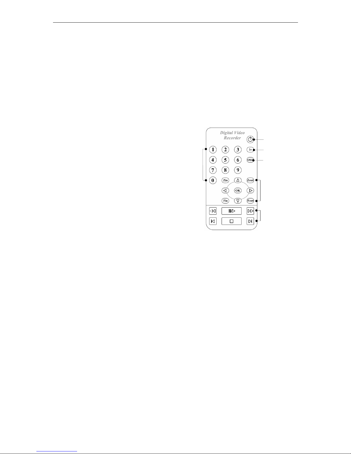
6. IR Remote Control
iFocus DVR come with three ways of control, using a Remote IR Controller, a PS2 keyboard
or a PC.
The PC can be connected to the DVR via LAN/WAN/Internet and remote operation program
runs fully on IE.
Only the IR remote controller programming will be discussed here.
Following sections are outline of the function of the individual key.
Power key: To turn on DVR
Numeric keys: direct function entry, system
parameter setting and channel fast switching
in live view and playback
“1-” key: channel fast switching (for channel
number greater than 9) in live view and
playback
On-screen-display key: To turn on or off
menu during menu operation and hide camera
title at live view
Arrows: to move cursor, control PTZ cameras
(see Chapter 15 for details) and configure
motion grip setting (see Chapter 12 for details)
“Zin” and “Z
out
”: to control PTZ cameras (see Chapter 15 for details)
“Fin” and “F
out
”: toggle between different menu selections and control PTZ cameras (see
Chapter 15 for details)
“OK” key: to confirm setting
Playback keys: To control playback (see Chapter 13 for details) and configure motion grip
setting (see Chapter 12 for details)
Figure 12: IR Remote Control
“1-” Key
Power Key
Numeric
Key
On-screendisplay
Arrow, zoom,
focus and “OK”
Key
Playback keys

iFocus DVRA+/B+/E+ Manual Version 4.2
Page 11 of 40
7. Power Up of DVR
7.1 AC Power Input Selector
Before you turn on your DVR, make sure that the AC power selector switch marked with
110/230V at the back of the DVR is set correctly to ensure that the right AC voltage is
being used. Wrong AC power switch selection may results in power supply damage due
to power overloading.
7.2 Power Up of DVR
Once the DVR is connected correctly according to the CCTV system requirements, it will
be ready for powering up. For the first time powered up, the factory default setting will be
loaded into the DVR for normal operation.
The DVR is designed with watch dog timer, which monitors the operation of main
program and resets the system if the program fails to perform correctly. The system is
also designed to recover from unexpected system interruption event. The watch dog timer
will reset the DVR and the recovering program will load the last valid system setting into
the DVR in order to ensure proper system boot-up and operation.
The power up process will take about 1-2 minutes before the camera live view screen is
displayed correctly. Please note that if the DVR is NOT properly powered down, there is
possibility of hard disk data corruption. Proper power down process means shutting down
the DVR from the Main Menu.
Once power up, the monitor display will be as shown below depend on the DVR model. 4
Channel will display in Quad mode, 8/ 9/ 16-Channel split.

iFocus DVRA+/B+/E+ Manual Version 4.2
Page 12 of 40
8. Full Screen Live View and DVR Log-in
8.1 Full Screen Live View
After power up the DVR, user can select any
camera full screen live view by keying the
channel number using IR controller. This
function does not require the user to login to the
main programming menu.
For camera numbers greater than 10, the user
should press the “1-” key followed by the next
digit. Example: “1-” followed by “6” for camera number 16.
8.2 Digital Zoom
iFocus DVR provide digital zoom for individual channels at four-time in the composite
video output.
To zoom a certain channel,
Key in the channel number using remote control to enter the full-screen mode
Press Stop button to enter the zoom mode
Use arrow keys to browse the enlarged live view
Press Stop button to exit the zoom mode
Press “0” key to exit the full-screen mode
8.3 Status Bar Display
The DVR user interface is a menu driven control user interface (UI). A full function of
the DVR menu is attached in Appendix for user reference. Once the DVR is powered up,
the status bar will be displayed at the bottom of the display screen, as shown below.
Figure 14: System Status Bar
8.4 Hiding of Camera Name
To hide camera names in the live view display, press “OSD” button on the remote
control.
Cam 01 Cam 01
Cam 01 Cam 01
Cam 01 Cam 01 Cam 01 Cam 01
Cam 01 Cam 01 Cam 01 Cam 01
Cam 01 Cam 01 Cam 01 Cam 01
Speed: [1.0] Rec 69% 01-12-2006 16:00:00
Cam16
Speed: [1.0] Rec 69% 01-12-2006 16:00:00
Figure 13: Full-screen Live View Operation
iFocus 16E+ 1.04 Press ‘OK’ for Menu Rec 69% 01-12-2006 16:00:00
DVR Model
DVR software version
Record
percentage
System date
and time

iFocus DVRA+/B+/E+ Manual Version 4.2
Page 13 of 40
8.5 Password Login
iFocus DVR provides two levels of operation. Below is the table showing the default
password and access right according to the user level.
User Level Default Password Access Rights
Supervisor 222222 All
Super User 111111
Local: Playback and Clear Alarm
Remote: Live View, Playback and Download
Normal User 333333
Local: Playback and Clear Alarm
Remote: Live View
To enter into the main menu:
a. Press "OK" key
b. Use numeric keys to key in password
c. Press "OK" key
Supervisor should change the password as and when required for greater security
protection. In the event that the user forgets the user password, the supervisor can change
the user password. However, if the supervisor forgets his/her own password, he/she shall
contact the DVR supplier for assistance. Supervisor should take note that the user and
supervisor passwords are also used for IE access authentication.

iFocus DVRA+/B+/E+ Manual Version 4.2
Page 14 of 40
9. Camera View Settings
The main menu will appear on the display screen after user has logged in.
Camera View menu includes DVR display settings. All functions discussed in this chapter are
under Camera View menu.
Under the Main Menu, press “1” to access camera view settings.
Figure 15: Menu, Camera View Setting
9.1 View Mode
The View Mode selection allows the user to change the display format as follow:
FULL: first available camera full screen
4 Split: camera 1st to 4th displayed in quad mode
9 Split: 3x3 segment display (for 8/16 Ch only)
16 Split: 4x4 segment display (for 16 Ch model only)
To change the view mode settings,
a. Under the camera view menu, press “1” to select “View Mode”
b. Use “Fin” or “F
out
” key to change settings
9.2 Spot Monitor Out (For DVRE+ models only)
iFocus E+ Model DVR support Spot TV output for additional display of full camera live
view for the camera selected. Available selections for the output mode are “fix”,
“sequential” and “Trig” mode.
For Fix mode,
a. Under the camera view menu, press “2” to select
“Spot TV Out”
b. Use “Fin” or “F
out
” key to select “Fix” for the first
field
c. Press right arrow key to move the cursor to the
second field
d. Use “Fin” or “F
out
” key to select camera
Main Menu
1 Camera View
2 Record
3 Playback
4 Trigger
5 Setup
6 Recording
[Off]
7 Arm
[Off]
8 Clear Alarm
9 Power Down
0 Exit
Camera View
1 View Mode [4 Split]
2 Spot TV Out [Fix] [Cam01]
3 Camera Display Properties
4 Camera Select [Cam01]
5 --Set Camera Name
6 --Camera View
[ On]
7 --Camera SAE [ On]
0 Exit
Camera View
1 View Mode [4 Split]
2 Spot TV Out [Fix] [Cam01]
3 Camera Display Properties
4 Camera Select [Cam01]
5 --Set Camera Name
6 --Camera View
[ On]
7 --Camera SAE [ On]
0 Exit
Figure 16: Menu, Spot TV Out
(Fix mode)

iFocus DVRA+/B+/E+ Manual Version 4.2
Page 15 of 40
For Sequential mode,
a. Under the camera view menu, press “2” to select “Spot
TV Out”
b. Use “Fin” or “F
out
” key to select “Seq” for the first
field
c. Press right arrow key to move the cursor to the second
field
d. Use “Fin” or “F
out
” key to select interval
Figure 17 illustrates the setting of sequential mode spot TV display with the interval set to
3 seconds.
Selection of the intervals can be 1-15/ 20/ 30 seconds.
During the Trig Mode, spot TV displays the live view of the
latest channel that has been detected with either external
trigger or motion trigger. The live view will be displayed
throughout the trigger period and the delay period before the
monitor goes back to blak screen.
To set Trig Mode for Spot TV,
a. Under the camera view menu, press “2” to select
“Spot TV Out”
b. Use “Fin” or “F
out
” key to select “Trig” for the first field
To ensure this feature is functioning properly, setting for the following parameters must
be correct:
a. External trigger setting (if Spot TV is to monitor the cameras equipped with
external trigger, refer to Chapter 12.1)
b. Motion trigger setting (if Spot TV is to monitor the cameras equipped with motion
detection, refer to Chapter 12.2)
c. System trigger delay (refer to Chapter12.2.3)
d. Trigger mode setting (this setting cannot be set to “Off”, refer to Chapter 11.6)
e. Record (this setting should be turned “On”, refer to Chapter 11)
9.3 Camera Display Properties
iFocus DVR provides adjustment of brightness, color and contrast for individual camera.
To change the setting,
a. Under the Camera View menu, press “3” for “Camera Display Properties”
The display would show the brightness, color and contrast in percentage for all the
cameras.
b. Use arrow keys to select the parameters
c. Use “F
in
” or “F
out
” keys to increase or decrease the property.
Camera View
1 View Mode [4 Split]
2 Spot TV Out [Seq] [3sec]
3 Camera Display Properties
4 Camera Select [Cam01]
5 --Set Camera Name
6 --Camera View
[ On]
7 --Camera SAE [ On]
0 Exit
Figure 17: Menu, Spot TV Out
(Sequential
mode)
Camera View
1 View Mode [4 Split]
2 Spot TV Out [Trig] [Auto]
3 Camera Display Properties
4 Camera Select [Cam01]
5 --Set Camera Name
6 --Camera View
[ On]
7 --Camera SAE [ On]
0 Exit
Figure 18: Menu, Spot TV Out
(
Trig
mode)

iFocus DVRA+/B+/E+ Manual Version 4.2
Page 16 of 40
Figure 19: Menu, Camera Display Properties
9.4 Camera Settings
iFocus DVR provides settings of camera name, view and Smart Adaptive Exposure
(SAE) for individual camera.
To change these settings, press “4” and use “F
in
” or “F
out
” keys to select the camera of
which the settings are going to be changed.
The followings are the settings available for each camera:
Camera Name
Camera View
Camera SAE
9.4.1 Set Camera Name
Camera title setting allows the user to assign meaning to the camera for easy memory.
As an example, “Lobby” and “Office” are more memorable than “Cam 01” and “Cam
02”.
To set the camera name,
a. Press “5” for “Set Camera Name”
b. Use “Fin” and “F
out
” key to change characters
c. Use arrow keys to move to the next character
d. Press “OK” to confirm the setting
[Note: this operation is done more easily on remote monitoring system. Refer to its
manual (soft copy in the user CD) for details. ]
9.4.2 Turn on or off camera view
Camera View allows the user to turn on or off the camera display at the local monitor
as well as remote monitoring system under normal user log-in mode. This is to disable
the camera display for those cameras located at sensitive locations.
To turn on or off the camera display,
a. Press “6” for “Camera View”
b. Use “F
in
” or “F
out
” keys to turn on or off the camera view
Camera Display Properties
CardNo Brt Color Ctrt
1 Card.1 [ 50] [ 35] [ 65]
2 Card.2 [ 50] [ 35] [ 65]
3 Card.3 [ 50] [ 35] [ 65]
4 Card.4 [ 50] [ 35] [ 65]
5 Card.5 [ 50] [ 35] [ 65]
6 Card.6 [ 50] [ 35] [ 65]
7 Card.7 [ 50] [ 35] [ 65]
8 Next page
0 Exit
Camera View
1 View Mode [4 Split]
2 Spot TV Out [Seq] [3sec]
3 Camera Display Properties
4 Camera Select [Cam01]
5 --Set Camera Name
6 --Camera View
[ On]
7 --Camera SAE [ On]
0 Exit

iFocus DVRA+/B+/E+ Manual Version 4.2
Page 17 of 40
9.4.3 Turn on or off Camera SAE function
Camera SAE function allows the system adjust the brightness level of individual
camera automatically according to the lighting condition thus improves the playback
video quality, suggested turn on for day-night cameras.
To turn on or off this function,
a. Press “7” for “Camera SAE”
b. Use “Fin” or “Fout” keys to turn on or off the camera view

iFocus DVRA+/B+/E+ Manual Version 4.2
Page 18 of 40
10. Setup Menu
Setup Menu includes system parameters settings. All functions discussed in this chapter are
under the Setup Menu.
Under the Main Menu, press “5” for “Setup” to access system setups.
Figure 20: Menu, Setup
10.1 Date/Time and Time Zone Setting
To change these settings,
a. Press “1” for “Date/ Time” under Setup Menu
c. Use arrow keys to move among different fields
d. Use numeric keys to key in date or time
[Note: Video after the newly-set time will be deleted.]
10.2 Password Change
To change the supervisor or the user password,
a. Press “3” for “Set Supervisor Pin” or
b. Press “4” for “Set User Pin”
c. Use arrow keys to move among different fields
d. Use numeric keys to key in new pins
e. Press down arrow key to select “Confirm”
f. Press “OK” to confirm the new pins
10.3 Storage Option
Under Storage Option, users could:
a. Clear all video, load default setting & reboot
b. Clear All Video & reboot
c. Reset Video Marker
Clear all video, load default setting & reboot: all video data will be erased and all system
configurations set back to factory default.
Clear all video & reboot: all video data will be erased while system configurations
remains
Reset video marker: the video marker (the “REC xx%” display at the status bar) to 0%.
Main Menu
1 Camera View
2 Record
3 Playback
4 Trigger
5 Setup
6 Recording
[Off]
7 Arm
[Off]
8 Clear Alarm
9 Power Down
0 Exit
Setup Menu
1 Date/Time
2 Time Zone Singapore
3 Supervisor Pin
4 User Pin
5 Storage Option
6 Communication
7 Key Lock
[Off]
8 Re-Init
[Off]
9 Archive to optical disc
0 Exit
Figure 21: Menu, Change Date/
Time
Change Date/Time
Date [dd-mm-yyyy]
Time [hh:mm:ss]
Video after this time will be
deleted.
‘Confirm’
‘Cancel’
Figure 22: Menu, Set
Supervisor Pin
Set Supervisor Pin
Supervisor Pin [ ]
Confirm Pin [ ]
‘Confirm’
‘Cancel’

iFocus DVRA+/B+/E+ Manual Version 4.2
Page 19 of 40
10.4 Communication
Communication menu includes settings of communication between DVR and other
devices such as PTZ cameras and remote PC.
Under the Setup Menu, press “6” for “Communication” to access the settings.
Figure 23: Menu, Communication
10.4.1 Modem Rings
The iFocus DVR can be connected to an external 56K modem. The Modem Ring
number indicates the number of rings after which the DVR will activate the modem
and get connected to the remote party.
10.4.2 TEL
This is reserved for future development.
10.4.3 Dial-out IP
This is reserved for future development.
10.4.4 Server IP
This is only applicable when DVR is connected to a CMS server. For more details,
refer to CMS user manual.
10.4.5 Server Port
This is only applicable when DVR is connected to a CMS server. For more details,
refer to CMS user manual.
10.4.6 DVR ID
The DVR ID is the identification number of the DVR. This is an additional security
feature to enhance the security on top of the DVR PIN. In order to remotely dial in to
the DVR, the user must enter the correct DVR ID and the Supervisor/User Pin.
Default is 0000000001 (10-digits).
10.4.7 PTZ, modem and matrix switch
iFocus DVR has a built-in feature for controlling Pan Tilt Zoom (PTZ) cameras using
IR Controller or remote monitoring system. It also can be programmed to interface
with matrix switch to control multiple PTZ cameras. iFocus DVR supports modem
dial in for remote monitoring system, too.
Connection wise, all three types of peripherals are interfacing with DVR through
PTZ Protocols that iFocus DVR support:
LILIN code in Menu: [LILIN PTZ]
Pelco D Protocol code in Menu: [PELCO D PTZ]
Communication
1 Modem Rings [ 1]
2 TEL [ ]
3 Dial Out IP [000.000.000.000]
4 Server IP [192.168.003.125]
5 Server Port [18375]
6 DVR ID [0000000001]
7 PTZ [LILIN PTZ]
8 Network Setting
0 Exit
Setup Menu
1 Date/Time
2 Time Zone Singapore
3 Supervisor Pin
4 User Pin
5 Storage Option
6 Communication
7 Key Lock
[Off]
8 Re-Init
[Off]
9 Archive to optical disc
0 Exit

iFocus DVRA+/B+/E+ Manual Version 4.2
Page 20 of 40
Yokogawa code in Menu: [YOKOGAWA PTZ]
Panasonic code in Menu: [PANASONIC PTZ]
VideoTec code in Menu: [VIDEOTEC PTZ]
Kalatel code in Menu: [KALATEL PTZ]
D-Max code in Menu: [D-MAX PTZ]
Modems that iFocus DVR support:
Prolink (PSTN Modem) code in Menu: [Pro 1456ESI]
AZTeck (PSTN Modem) code in Menu: [Aztech/ Pro-TR]
iTegno (GPRS Modem) code in Menu: [iTegno]
Matrix switches that iFocus DVR support:
All that using Pelco ASCII code in Menu: [PELCO A PTZ]
10.4.8 Network Setting
Each DVR that uses TCP/IP protocol must have a unique IP address.
If the DVR is connected in a LAN/WAN environment via the RJ45 network
connector, the IP address, Net Mask and Gateway must be obtained from the Network
Administrator.
If the DVR is connected to the ADSL/SDSL modem (for internet access), the ADSL
router should be programmed to forward all the external ports to the internal port of
the DVR IP address. For DNS setting, please refer to the ISP provider. The default
HTTP port is 80 and video port 33330.
To change the network settings,
a. Press “8” for “Network Setting” under Communication Menu
b. Use arrow keys to move among different fields
c. Use numeric keys to key in IP or port number
d. Use down arrow key to select “Confirm”
e. Press “OK” to confirm the new settings
Figure 24: Menu, Network Setting
Setup Menu
1 Date/Time
2 Time Zone Singapore
3 Supervisor Pin
4 User Pin
5 Storage Option
6 Communication
7 Key Lock
[Off]
8 Re-Init
[Off]
9 Archive to Optical Disc
0 Exit
Communication
1 Modem Rings [ 1]
2 TEL [ ]
3 Dial OutIP [000.000.000.000]
4 Server IP [192.168.003.125]
5 Server Port [18375]
6 DVR ID [0000000001]
7 PTZ [LILIN PTZ]
8 Network Setting
0 Exit
Network Setting
IP Address [192.168.001.222]
Subnet Mask [255.255.255.000]
Gateway [192.168.001.021]
1st DNS [165.021.083.088]
2nd DNS [161.000.000.000]
HTTP Port [00080]
MAC Address 00161777FFB2
‘Confirm’ (DVR will Reboot)
‘Cancel’

iFocus DVRA+/B+/E+ Manual Version 4.2
Page 21 of 40
10.5 Key Lock
“Key Lock” function prevents the DVR from being accidentally activated or triggered by
the remote controller. After turning on this function, user has to press the power key
followed by keying a four-digit number prompted by the DVR to activate the remote
controller.
10.6 Re-Init
“Re-Init” function helps the DVR system clear its network traffic by rebooting the DVR
every 3 A.M.
10.7 Archive to Optical Disc (For DVR with CD/ DVD-RW option only)
For DVR that have a built-in CD/ DVD-RW option, archiving is made easier.
To access the menu, press “9” for “Archive to Optical Disc” under setup menu.
Figure 25: Menu, Archive to Optical Disc
For archiving the data to an optical disc,
a. Press “3” for “Camera Source” under Archive to
Optical Disc menu
b. Use arrow keys to move among different fields
c. Use “Fin” or “F
out
” keys to turn on or off the camera
source for archiving
d. Press “0” to exit to Archive to Optical Disc menu
e. Press “1” for CD archiving or “2” for DVD archiving
f. Use arrow keys to move among different fields
g. Use numeric keys to key in start date/ time and end
date/ time for archiving
h. Allow the system to transfer the video data into
archiving buffer before proceed to set the next
segment
i. Use arrow key and move cursor to “Burn CD” or
“Burn DVD” and press “OK” key
j. Disk will be ejected automatically after burning
process is completed.
To playback the content of the CD, refer to Chapter 13 for details.
For Panic Burnt function, please refer to Chapter 0 for details.
Date/Time Selection for DVD
1 Start 1[02-10-2004 16:22:00]
2 End 1 [02-10-2004 17:22:00]
3 Start 2 [dd-mm-yyy hh:mm:ss]
4 End 2 [dd-mm-yyy hh:mm:ss]
5 Start 3 [dd-mm-yyy hh:mm:ss]
6 End 3 [dd-mm-yyy hh:mm:ss]
7 Burn DVD
Usage: 30%
0 Exit
Camera Source
1 Camera 1[ On] 9[ On]
2 Camera 2 2[ On] 10[ On]
3 Camera 3 3[ On] 11[ On]
4 Camera 4 4[ On] 12[ On]
5 Camera 5 5[ On] 13[ On]
6 Camera 6 6[ On] 14[ On]
7 Camera 7 7[ On] 15[ On]
8 Camera 8 8[ On] 16[ On]
0 Exit
Figure 27: Menu, Camera
Source
Figure 27: Menu, Date/ Time
Selection for Optical Disc
Setup Menu
1 Date/Time
2 Time Zone Singapore
3 Supervisor Pin
4 User Pin
5 Storage Option
6 Communication
7 Key Lock
[Off]
8 Re-Init [Off]
9 Archive to optical disc
0 Exit
Archive to Optical Disc
1 Date/Time selection for CD
2 Date/Time selection for DVD
3 Camera Source
0 Exit

iFocus DVRA+/B+/E+ Manual Version 4.2
Page 22 of 40
[Note: burning process is completed only when the CD/ DVD-RW drive automatically
ejects or when the CD/ DVD-RW LED is completely turned OFF. If there is any
interruption during the process, the optical disc will not be readable.]

iFocus DVRA+/B+/E+ Manual Version 4.2
Page 23 of 40
11. Record Menu
The Record Menu includes record settings such as recording frame rate and record mode. The
Timer schedules and Holidays are also programmed here.
Turn off recording before changing any record setting. Instructions:
a. Press “6” for “Recording” under the Main Menu
b. Use “Fin” or “F
out
” keys to turn off recording (same way to turn on recording)
Press “2” for “Record” under main menu to access record settings.
Figure 28: Menu, Record
11.1 Record Info
Record information is provided in this menu, which includes:
First Video: the date and time of earliest recorded video
Marker: the recording reference used for the record percentage
Storage Capacity: DVR hard disk size
S/W Version: the software version of the DVR
F/W Version: the firmware version of the DVR
WebDVR Version: the remote monitoring system version
Figure 29: Menu, Record Info
To access the Record Info Menu, press “1” for “Record Info” under Record Menu.
11.2 Record Mode
In the Record Menu, record modes can be set. Below are the recording resolutions in
different modes:
Main Menu
1 Camera View
2 Record
3 Playback
4 Trigger
5 Setup
6 Recording
[Off]
7 Arm
[Off]
8 Clear Alarm
9 Power Down
0 Exit
Record Menu
1 Record Info
2 Record Mode [MIX]
3 Frame Rate
4 Manual [ On]
5 Trigger [Off]
6 Timer
[Off]
7 Timer Setting
8 Holiday Setting
9 Quality [High]
0 Exit
Record Info
First Video 45.31%
dd-mm-yyy hh:mm
Marker 25.23%
dd-mm-yyy hh:mm
Storage Capacity 500.2GB
S/W Version 1.04.002
F/W Version 5.05.001
WebDVR Version 0.00.000
0 Exit
Record Menu
1 Record Info
2 Record Mode [MIX]
3 Frame Rate
4 Manual [ On]
5 Trigger [Off]
6 Timer
[Off]
7 Timer Setting
8 Holiday Setting
9 Quality [High]
0 Exit

iFocus DVRA+/B+/E+ Manual Version 4.2
Page 24 of 40
PAL NTSC
CIF 352x288 320x240
FULL 704x576 640x480
CIF: CIF recording for all channels
FULL: Full screen recording for all channels
MIX: Mixture of CIF and FULL resolution (For E Model only)
Full screen for all cameras is recommended for best playback quality. However, more
hard disk space will be used.
11.3 Frame Rate and Audio Record Setting
To access the Frame Rate menu, press “3” for “Frame Rate” under Record Menu.
Figure 30: Menu, Audio Recording Setting
11.3.1 Frame Rate and Record Mode
The maximum recording frame rates for every model are listed below:
DVR8A+ (PAL/NTSC) 32 FPS (Frame per second), CIF/FULL
DVR16B+ (PAL/NTSC) 64 FPS in CIF/FULL
DVR4E+ (PAL) 100 FPS, CIF/FULL
DVR4E+ (NTSC) 100 FPS, CIF/FULL
DVR8/16E+(PAL) 200 FPS, CIF
100 FPS, FULL
DVR8/16E+ (NTSC) 240 FPS, CIF
120 FPS, FULL
11.3.2 Audio Record Setting
To set audio recording,
a. Use arrow keys to move among different fields
b. Use “Fin” or “F
out
” keys to turn on or off audio
recording at the first column of first two channels
c. Use “Fin” or “F
out
” keys to set recording frame
rate for audio-recording channels
11.4 Record Schedule
The following record schedule can be programmed independently. It should be taken note
that the Manual recording will over write the trigger and timer recording as it is a 24
hours recording mode.
Manual: equivalent to 24 hours continuous recording
Frame Rate
1 Camera 1 [Off] [ 25] CIF
2 Camera 2 [ On] [ 25] CIF
3 Camera 3 [12.5] CIF
4 Camera 4 [0.25] CIF
5 Camera 5 [12.5] Full
6 Camera 6 [ 25] Full
7 Camera 7 [ 25] Full
8 Camera 8 [ 8] Full
9 Next Page
0 Exit Total: 178.75
Record Menu
1 Record Info
2 Record Mode [MIX]
3 Frame Rate
4 Manual [ On]
5 Trigger [Off]
6 Timer
[Off]
7 Timer Setting
8 Holiday Setting
9 Quality [High]
0 Exit
Frame Rate
1 Camera 1 [Off] [ 25] CIF
2 Camera 2 [ On] [ 25] CIF
3 Camera 3 [12.5] CIF
4 Camera 4 [0.25] CIF
5 Camera 5 [12.5] Full
6 Camera 6 [ 25] Full
7 Camera 7 [ 25] Full
8 Camera 8 [ 8] Full
9 Next Page
0 Exit Total: 178.75
Figure 31: Menu, Frame Rate
(Audio Recording)

iFocus DVRA+/B+/E+ Manual Version 4.2
Page 25 of 40
Trigger: Record based on either motion detection or external alarm trigger setting
Timer: Users can program a fixed time schedule for weekdays, Saturday, Sunday
and Holiday timer recording.
11.5 Manual Recording
For continuous recording,
a. Press “4” for “Manual” under
Record Menu
b. Use “Fin” or “F
out
” to turn on or
off manual mode
11.6 Trigger Recording
Trigger recording mode includes motion
trigger (record upon motion detection)
and external trigger (record upon external
device triggering).
Setting must be correct in both Trigger Menu and Record Menu in order for DVR system
to perform trigger recording. The detail of motion and trigger setting will be discussed in
the Chapter 12.
To activate the trigger recording, turn on “Trigger” in Record Menu and “Recording” in
Main Menu.
iFocus DVR support Intelligent Trigger Recording. Under this trigger recording mode,
the frame rate during idle period (when there is no motion or external trigger) and
detection period is different.
The table below shows the frame rate of different periods for each available trigger
selections:
Trigger Selections Idle Period Detection Period
Off
N.A. N.A.
Trg0
0FPS/Ch User-defined
Trg1
1FPS/Ch User-defined
Trg2
0.5FPS/Ch User-defined
Trg3
User-defined Highest 25FPS/Ch
[Note: to set the user-defined frame rate, refer to Chapter 11.3]
11.7 Timer Recording
Under this mode, DVR starts and stops recording according to the Timer and Holiday
setting in the Record menu.
11.7.1 Timer Setting
Press “7” to enter the Timer Setting menu under Record Menu.
Weekday Timer is for Monday to Friday while the Weekend Timer 1 is for Saturday
and the Weekend Timer 2 for Sunday.
Record Menu
1 Record Info
2 Record Mode [MIX]
3 Frame Rate
4 Manual [ On]
5 Trigger [Trg0]
6 Timer [ Trg
]
7 Timer Setting
8 Holiday Setting
9 Quality [High]
0 Exit
Figure 32: Menu, Record Menu
(Manual, Trigger, Timer and Quality)
Chapter 12.5
Manual
Recording
Chapter 12.6
Trigger
Recording
Chapter 12.7
Timer
Chapter 12.8
Record Quality

iFocus DVRA+/B+/E+ Manual Version 4.2
Page 26 of 40
Turn on “6 Timer” under the Record Menu to activate the timer recording.
Figure 33: Menu, Timer Setting
11.7.2 Holiday Setting
iFocus DVR support holiday schedule recording up to 21 holiday timers in a year.
Press “8” under Record Menu to enter Holiday Setting menu. Use numeric keys to
program the Start and End Time as well as the Dates. Use arrow keys to move the
cursor among different fields.
Figure 34: Menu, Holiday Setting
11.8 Record Quality
Record quality is defined by the video compression rate. The higher rate, the lower
quality and smaller hard disk space consumption.
There are 3 options under record quality setting for iFocus DVR, Normal, High and
Super. When setting the recording quality, users should consider their desire video quality
and the recording period according to their needs in the CCTV application.
Record Menu
1 Record Info
2 Record Mode [MIX]
3 Frame Rate
4 Manual [ On]
5 Trigger [Off]
6 Timer [On
]
7 Timer Setting
8 Holiday Setting
9 Quality [High]
0 Exit
Timer Setting
1 Weekday Timer
2 Start [09:00]
3 End [09:00]
4 Weekend Timer 1 [Sat]
5 Start [09:00]
6 End [09:00]
7 Weekend Timer 2 [Sun]
8 Start [09:00]
9 End [09:00]
0 Exit
Record Menu
1 Record Info
2 Record Mode [MIX]
3 Frame Rate
4 Manual [ On]
5 Trigger [Off]
6 Timer
[Off]
7 Timer Setting
8 Holiday Setting
9 Quality [High]
0 Exit
Holiday Setting
1 Start [00:00]
2 End [23:59]
3 Date [01-01][01-01][01-01]
4 Date [01-01][01-01][01-01]
5 Date [01-01][01-01][01-01]
6 Date [01-01][01-01][01-01]
7 Date [01-01][01-01][01-01]
8 Date [01-01][01-01][01-01]
9 Date [01-01][01-01][01-01]
0 Exit

iFocus DVRA+/B+/E+ Manual Version 4.2
Page 27 of 40
12. Trigger Settings
iFocus DVR integrate both external and motion trigger recording in its operation,
programming of which available under the Trigger Menu.
Under the Main Menu, press “4” to enter Trigger Menu.
Figure 35: Menu, Trigger Menu
12.1 External Trigger
iFocus DVR can be programmed to both start recording and sent out email upon external
devices being triggered.
Settings available under External trigger menu. Press “4” under Trigger Menu to access
the setting.
Figure 36: Menu, External Trigger
Available options:
Off: External trigger not in use
Vxx: To program the correspondent channel start recording upon trigger
ARM: To activate email alert upon trigger
[Note: Network settings must be correct in order for DVR to perform email alert. Refer
to Chapter 12.3 or iFocus Remote Monitoring System User Manual for details.]
Trigger Menu
1 External Trigger
2 Motion Trigger
3 Motion Properties Adj[Cam01]
4 --Motion Grid Setting
5 --Motion Sensitivity
[High]
6 System Trigger Delay
[120]
7 System Arm Delay [120]
0 Exit
Main Menu
1 Camera View
2 Record
3 Playback
4 Trigger
5 Setup
6 Recording
[Off]
7 Arm
[Off]
8 Clear Alarm
9 Power Down
0 Exit
Trigger Menu
1 External Trigger
2 Motion Trigger
3 Motion Properties Adj[Cam01]
4 --Motion Grid Setting
5 --Motion Sensitivity
[High]
6 System Trigger Delay
[120]
7 System Arm Delay [120]
0 Exit
External Trigger
1 Trigger1 [Arm]+[V03]
2 Trigger2 [Off]+[Off]
3 Trigger3 [Off]+[Off]
4 Trigger4 [Off]+[Off]
5 Trigger5 [Off]+[Off]
6 Trigger6 [Off]+[Off]
9 Trigger 2 Clear Alarm [ On]
0 Exit

iFocus DVRA+/B+/E+ Manual Version 4.2
Page 28 of 40
12.2 Motion Trigger
iFocus DVR are built in with Video Motion Detection (VMD) for individual video
channel. VMD sensitivity and zone can be set independently for each channel available
under Motion Trigger Menu.
Under the Trigger Menu, press “2” to access Motion Trigger Menu.
Figure 37: Menu, Motion Trigger
The setting of the motion trigger is shown in the following diagram. Similarly, the motion
trigger can be programmed with the following options.
Off: No Motion Trigger
On: To enable the VMD function of a particular channel
ARM: To enable the email alert function of the particular channel
12.2.1 Motion Grid Setting
Under the Trigger Menu, user can
program the motion detection areas
for individual camera.
To enter motion detection grid setting
for a particular channel,
a. Press “3” for “Motion
Properties Adj” under the
Trigger Menu.
b. Use “Fin” or “F
out
” key to
select this channel
c. Press “4” to access Motion Grid Setting
The full screen view of the channel
will be displayed with ten-dot motion
detection zone. When dots are grouped
as shown in Group A in Figure 37,
only areas within the dot-area is
equipped with VMD. When dots are
spread as shown in Group B, full
screen VMD is enabled.
To set the motion grid for a channel
through remote control,
a. Use “Play” Key to toggle between Group A and B
b. Use arrow keys to change the position of the dot-area
c. Use fast forward and rewind key to change the coverage of the dot-area
Motion Trigger
1 Motion1 1[ On] 9[Off]
2 Motion2 2[Off] 10[ On]
3 Motion3 3[Arm] 11[Arm]
4 Motion4 4[Arm] 12[Arm]
5 Motion5 5[Off] 13[Off]
6 Motion6 6[Arm] 14[ On]
7 Motion7 7[ On] 15[Off]
8 Motion8 8[Arm] 16[ On]
0 Exit
Trigger Menu
1 External Trigger
2 Motion Trigger
3 Motion Properties Adj[Cam01]
4 --Motion Grid Setting
5 --Motion Sensitivity
[High]
6 System Trigger Delay
[120]
7 System Arm Delay [120]
0 Exit
Trigger Menu
1 External Trigger
2 Motion Trigger
3 Motion Properties Adj[Cam01]
4 --Motion Grid Setting
5 --Motion Sensitivity
[High]
6 System Trigger Delay
[120]
7 System Arm Delay [120]
0 Exit
Figure 38: Menu, Trigger Menu
(Motion Properties and System Trigger Delay)
Chapter 12.2.1
Motion Grid
Setting
Chapter 12.2.2
Motion
Sensitivity
Chapter 12.2.3
System Trigger
Delay
Group A: Two
Group B:
Full
Figure 39: Default Motion Grid Setting

iFocus DVRA+/B+/E+ Manual Version 4.2
Page 29 of 40
12.2.2 Motion Sensitivity
To cater for different environment application and maximize the motion trigger
function, iFocus DVR Motion Sensitivity can be set to [Low], [Mid] or [High] under
the Trigger Menu.
To set motion sensitivity for particular channel,
a. Press “3” for “Motion Properties Adj” under the Trigger Menu.
b. Use “Fin” or “F
out
” key to select the channel
c. Press “5” to select motion sensitivity setting
d. Use “Fin” or “F
out
” key to set different sensitivity
12.2.3 System Trigger Delay Setting
The System Trigger Delay Setting is to set the delay for the timer. The recording will
stop after the delay timer is expired upon deactivation of Trigger. If the trigger is
activated within the count down delay time, the delay timer will restart from
beginning again. Trigger Delay time can be adjusted from 10 to 120 seconds.
12.3 Email Alert
The DVR can be programmed to send email to the users upon external trigger, motion
trigger or system events. Upon alert, the event name and four video frames (for motion
trigger events only) will be sent out. Refer to iFocus Remote Monitoring System User
Manual for the setup.
The email alert can be triggered by the following events:
Video Motion Detection (VMD) Alarm
External Trigger Alarm
System Event (video drop, record on, etc)
To program email alert upon external trigger 1 alarm, following parameters must be set:
IP address (under Communication Menu), refer to chapter 10
External Trigger for ARM events (under Trigger menu), refer to chapter 12
Trigger Recording (under Record Menu), refer to chapter 11
Recording (under Main Menu)
ARM (under Main Menu)
Arm delay is the time interval between arming and alarm
dial-out, which is adjustable for iFocus DVR.
To set arm delay,
a. Press “7” under Trigger Menu
b. Use “F
in
” or “F
out
” keys to change the setting
Trigger Menu
1 External Trigger
2 Motion Trigger
3 Motion Properties Adj[Cam01]
4 --Motion Grid Setting
5 --Motion Sensitivity
[High]
6 System Trigger Delay
[120]
7 System Arm Delay [120]
0 Exit
Figure 40: Menu, Trigger
Menu (Arm Delay)

iFocus DVRA+/B+/E+ Manual Version 4.2
Page 30 of 40
13. Playback
Playback menu includes playback operations for recorded video.
To enter the playback menu, press “3” under the main menu using remote control.
Figure 41: Menu, Playback Menu
iFocus DVR supports event and date/ time playback. Description of the two methods:
Event: Used when the DVR is set to Trigger Recording. Users can review the
trigger events to search for the desire events with precise date and time
information prior to playback of video. This will cut down the
evaluation and investigation time significantly.
Date/Time: Used to playback a period of video based on its date and time
Once the DVR is in Playback model, the Date/Time displayed at the bottom right hand corner
will be the playback date/time. Under Live View, the Date/Time will display the current
date/time.
13.1 Event Playback
The following example illustrates how to playback videos dated before 5.00pm on 01 Dec
2006 based on event playback.
a. Press “8” under Playback Menu
b. Use numeric keys to change the date field to “01-12-2006”
c. Press Down arrow key
d. Use numeric keys to change the time field to “17:00:00”
e. Use arrow keys to move the cursor to “7 Event List” and press “OK”
f. Use numeric keys to select an event
g. Press “3” under Playback Menu to start playback
h. Press stop button to exit the playback mode
Figure 42: Menu, Event List
Event List
1 Page Up
2 01-12 16:04:08 Motion12 on
3 01-12 16:03:55 Motion4 on
4 01-12 16:03:53 Motion4 off
5 01-12 16:03:51 Power up
6 01-12 16:03:49 Power down
7 01-12 16:02:56 Motion1 off
9 01-12 16:02:50 Motion1 on
9 Page Down
0 Exit
Playback Menu
1 Playback Screen [ Auto]
2 Camera Source
3 Play
4 Direction [>]
5 Speed [ 1]
6 Event Option
7 Event List
8 Date [01-12-2001]
9 Time [17:00:00]
0 Exit
Main Menu
1 Camera View
2 Record
3 Playback
4 Trigger
5 Setup
6 Recording
[Off]
7 Arm
[Off]
8 Clear Alarm
9 Power Down
0 Exit
Playback Menu
1 Playback Screen [ Auto]
2 Camera Screen
3 Play
4 Direction [>]
5 Speed [ 1]
6 Event Option
7 Event List
8 Date [19-10-2007]
9 Time [17:00:00]
0 Exit

iFocus DVRA+/B+/E+ Manual Version 4.2
Page 31 of 40
13.2 Date/Time Playback
In the Date/Time Playback method, the same setting method of Date and Time fields
discussed in the Event Playback method is still applicable. Once the date and time fields
are entered, user can press the Play key “3” to start playing the recording video. If there is
no video available for playback, “No Video” will be displayed on all channels.
13.3 Playback Screen Setting
In the PLAYBACK menu, Playback Screen can be set to Auto/FULL/4/9/16.
Auto: Playback screen will be adjusted automatically based on the number of
cameras selected for simultaneous playback.
FULL: Playback the first selected camera in FULL screen
4: Playback the first 4 selected cameras in 2x2 screen
9: Playback the first 9 selected cameras in 3x3 screen (for 8/16-Ch DVR)
16: Playback all the selected cameras in 4x4 screen (for 16-Ch DVR)
Users are recommended to set the Playback Screen to “Auto” mode in normal application.
13.4 Playback Control Function
Once in Playback mode, the MENU will disappear and the playback control is transfer to
the Playback Control Keys located on lower part of the IR controller
Key functions:
a. Play: Play the next frame under
Single Frame Playback (SFP)
mode or resume playback when
the video has been paused
b. Pause: pause playback
c. Fast forward: change the
direction of playback to forward
or change the playback speed
from SFP to 8 times playback
d. Backward: change the direction of playback to backward and speed adjusted to 8
times automatically
e. Play next/ last: jump to the next or last event
f. Stop: exit from the playback mode
During playback, the status bar display will be as shown below:
Figure 44: Status Bar, Playback
Figure 43: Remote Control Keys, playback control
Backward
Forward
Pause/ Play
Play last
Play next
Stop
Speed: [1.0] > [892 of 1290] Rec 69% 01-12-2006 16:00:00
Playback speed
Playback direction
Curr
ent event
Current event
Record
percentage
Playback date
and time

iFocus DVRA+/B+/E+ Manual Version 4.2
Page 32 of 40
13.5 Camera Source Setting
To choose particular camera sources for playback,
a. Press “2” under Playback menu to access Playback Camera Source menu
b. Use arrow keys to move among different fields
c. Use “Fin” or “F
out
” key to turn on or off the camera source
To playback the video with audio source, turn on its camera source first. Selection is
available under “9 Audio Ch”.
Figure 45: Menu, Camera Source Setting
[Note: For audio playback on 16-Channel DVR, please turn off the playback camera
source of Camera 9-16
For playback at x02/x04/x08 speed, audio will be muted automatically.]
13.6 Full Screen Playback
To view the full screen of certain channel
during playback,
a. Press the key representing the channel
number during screen-splitting mode
b. Press “1-” and then the numeric key if
the channel number greater than 9
c. Press “0” to return to the screen-splitting
mode
13.7 Playback with IFS Player
Only iFocus IFSPlayer can be used to playback video archived into CD/ DVD-R
downloaded by the remote monitoring system on a PC.
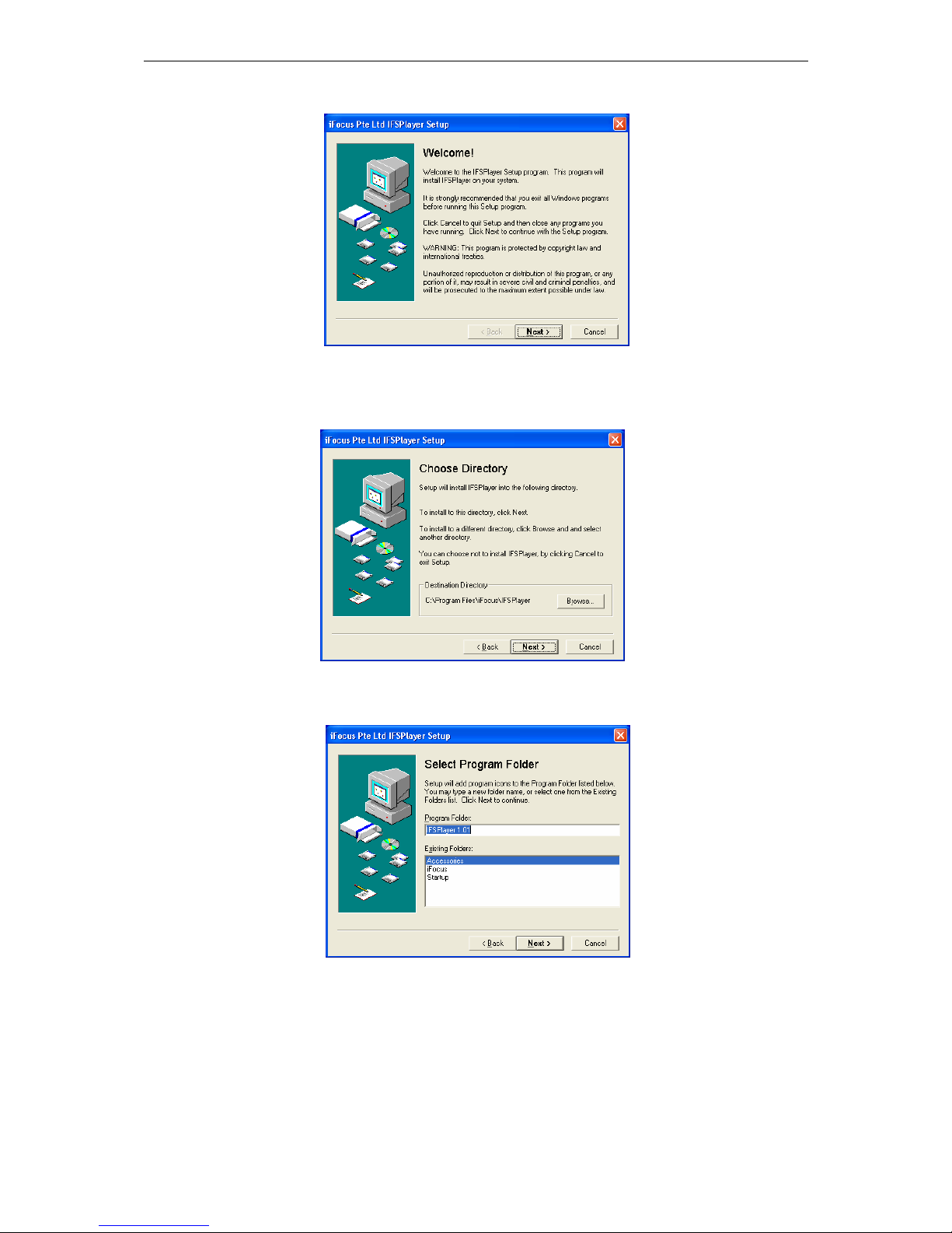
13.7.1 Installing IFS Player
To install the software in the PC,
a. Run the file CLIENT\iFxIFSPlayer.EXE in the User CD
Figure 47: Procedure, Installing IFS Player 1
Playback Menu
1 Playback Screen [ Auto]
2 Camera Source
3 Play
4 Direction [>]
5 Speed [ 1]
6 Event Option
7 Event List
8 Date [19-10-2007]
9 Time [17:00:00]
0 Exit
Playback Camera Source
1 Camera 1[ On] 9[ On]
2 Camera 2[ On] 10[ On]
3 Camera 3[ On] 11[ On]
4 Camera 4[ On] 12[ On]
5 Camera 5[ On] 13[ On]
6 Camera 6[ On] 14[ On]
7 Camera 7[ On] 15[ On]
8 Camera 8[ On] 16[ On]
9 Audio Ch 1[ On] 2[ Off]
0 Exit
Cam 01 Cam 01 Cam 01 Cam 01
Cam 01 Cam 01 Cam 01 Cam 01
Cam 01 Cam 01 Cam 01 Cam 01
Cam 01 Cam 01 Cam 01 Cam 01
Speed: [1.0] Rec 69% 01-12-2006 16:00:00
Cam16
Speed: [1.0] Rec 69% 01-12-2006 16:00:00
Figure 46: Full-Screen to Splitting
Screen Switching during Playback
iFocus DVRA+/B+/E+ Manual Version 4.2
Page 33 of 40
b. Click “Next” to continue when “Welcome!” message popped
Figure 48: Procedure, Installing IFS Player 2
c. Click “Next” to continue. To choose another directory, click the “Browse”
button.
Figure 49: Procedure, Installing IFS Player 3
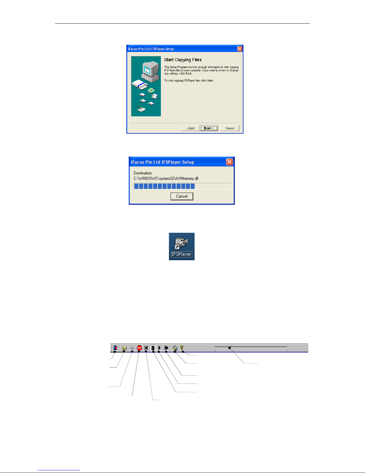
d. Click “Next” to continue.
Figure 50: Procedure, Installing IFS Player 4
iFocus DVRA+/B+/E+ Manual Version 4.2
Page 34 of 40
e. Click “Next” to start copying files to your computer.
Figure 51: Procedure, Installing IFS Player 5
f. A progress bar will appear.
Figure 52: Procedure, Installing IFS Player 6
g. Once the IFS Player is installed, a shortcut icon will be shown on the Window
main screen.
Figure 53: Icon, IFS Player
13.7.2 Getting Started with IFS Player
To start the software program, double-click on the DVR Player icon. When the
program starts running, double click on the CD-ROM. The video segment that has
been archived will display. To playback the CD, double click on the segment.
During playback, double-click on a particular video for a full screen display. To
return to the multiplex display of the video, double click on the screen again.
The buttons on the menu bar and their functions are shown below:
Figure 54: Playback Control using IFS Playback
Exit
Go to
parent
directory
Go up
Exit
Return to start
position
Help
Export to AVI
format
Fast forward
Play
Pause
Select different
Playback Time
within the same
video segment.
iFocus DVRA+/B+/E+ Manual Version 4.2
Page 35 of 40
14. Modem Dial In Basic Setup
14.1 Installing Setup Program for Modem Dial In
To dial in through analogue modem, user needs to install the Dialer application into the
PC. The Dialer application is for dialing to the DVR through modem.
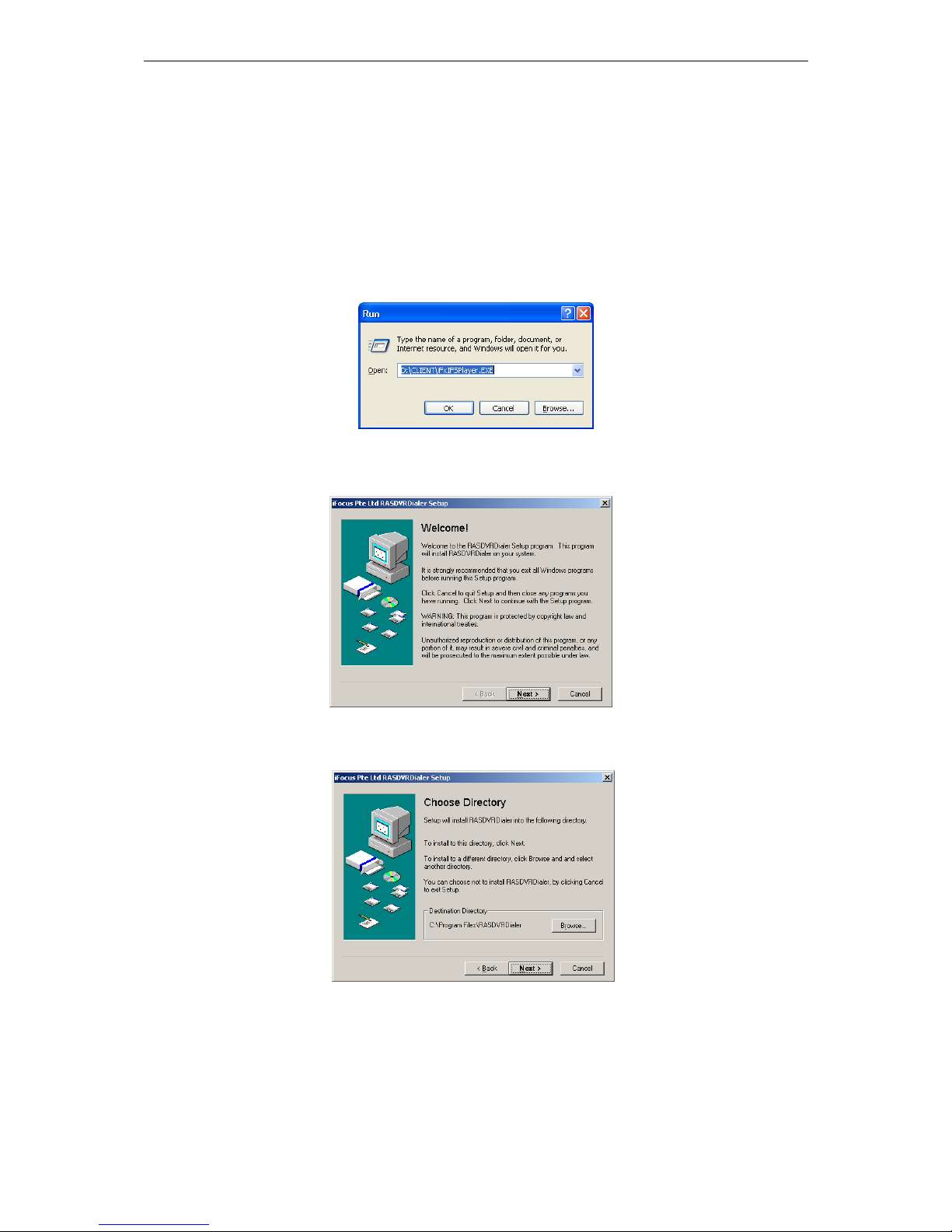
14.1.1 Installing RAS DVR Dialer Application Software
To install the dial-up program,
a. Run the file CLIENT\iFxIFSPlayer.EXE in the User CD
Figure 55: Icon, RAS DVR Dialer
b. The following dialogue box will appear. Click “Next”:
Figure 56: Procedure, Installing RAS DVR Dialer 1
c. Choose Destination Directory for installation and click “Next”:
Figure 57: Procedure, Installing RAS DVR Dialer 2

iFocus DVRA+/B+/E+ Manual Version 4.2
Page 36 of 40
d. Select Program Folder and click “Next”:
Figure 58: Procedure, Installing RAS DVR Dialer 3
e. Click "Next" to Start Copying Files:
Figure 59: Procedure, Installing RAS DVR Dialer 4
f. Click "Finish" when installation is completed:
Figure 60: Procedure, Installing RAS DVR Dialer 5
14.1.2 Setting up The RAS DVR Dialer
a. On the desktop, double-click RAS DVR Dialer to run the program:
Figure 61: Icon, RAS DVR Dialer

iFocus DVRA+/B+/E+ Manual Version 4.2
Page 37 of 40
b. Step 2: Select “Add New” to add a new dial up number:
Figure 62: Procedure, Setting up RAS DVR Dialer 1
c. Select “Dial up to Private Network”:
Figure 63: Procedure, Setting up RAS DVR Dialer 2
d. Select Modem that is installed in the PC:
Figure 64: Procedure, Setting up RAS DVR Dialer 3

iFocus DVRA+/B+/E+ Manual Version 4.2
Page 38 of 40
e. Key in the phone number of the DVR site:
Figure 65: Procedure, Setting up RAS DVR Dialer 4
f. Step 6: Select “Only for myself”:
Figure 66: Procedure, Setting up RAS DVR Dialer 5
g. Finished - enter a name for the Dial Up Connection:
When dialing, key in the DVR ID as the USER NAME (default 0000000001).
The password is 333333.
Figure 67: Procedure, Setting up RAS DVR Dialer 6
14.2 Modem Dial-in Setting
To set the DVR for modem dial in,
a. Connect a modem to DVR COM port
c. Power ON the Modem
d. Log in to the Main Menu using the default password 222222
e. Make sure the recording has been turned off
f. Go to Setup -> Communication

iFocus DVRA+/B+/E+ Manual Version 4.2
Page 39 of 40
g. Under PTZ, select the modem protocol
Figure 68: Menu, Modem Protocol
h. The DVR will Re-start after the confirmation
14.3 Configuration of the RAS DVR Dialer for Dialing
At the PC side, please follow these steps for dialing to the DVR:
b. Double click on the RAS DVR Dialer icon
c. Select “Dial”, the Connect Dial-up Connection dialogue box will appear
Figure 69: Procedure, Configuration of RAS DVR Dialer 1
d. Key in the DVR ID as the USER NAME (default 0000000001). Use the DVR
normal user password as the RAS Dialer password
e. Key in the Dial as the Phone Number
f. Click on “Dial”
[Note: For the details of the IE dial in, refer to the IE Dial in Manual in the CD]
Setup Menu
1 Date/Time
2 Time Zone Singapore
3 Supervisor Pin
4 User Pin
5 Storage Option
6 Communication
7 Key Lock
[Off]
8 Re-Init
[Off]
9 Archive to optical disc
0 Exit
Communication
1 Modem Rings [ 1]
2 TEL [ ]
3 Dial OutIP [000.000.000.000]
4 Server IP [192.168.003.125]
5 Server Port [18375]
6 DVR ID [0000000001]
7 PTZ [Prolink Modem]
8 Network Setting
0 Exit

iFocus DVRA+/B+/E+ Manual Version 4.2
Page 40 of 40
15. Pan/Tilt/Zoom Control
iFocus DVR support local as well as remote Pan/Tilt/Zoom (PTZ) control.
Protocols supported:
Merit Li Lin
Pelco D-prototype
Yokogawa
Panasonic
VideoTec
Kalatel
D-Max
These functions can be controlled through:
IR Remote controller
PS2 Keyboard
Remote access as supervisor using IE program
To set the PTZ protocol,
Figure 70: Menu, PTZ control
Press “6” at the main menu for “6 Communication”
a. Press “7” at Communication menu to highlight PTZ protocol selection
b. Use “Fin” or “Fout” key to select PTZ protocol
To control PTZ,
a. Select the PTZ camera for full screen live view
b. Follow figure 71 for PTZ control using remote
control
Setup Menu
1 Date/Time
2 Time Zone Singapore
3 Supervisor Pin
4 User Pin
5 Storage Option
6 Communication
7 Key Lock
[Off]
8 Re-Init
[Off]
9 Archive to optical disc
0 Exit
Communication
1 Modem Rings [ 1]
2 TEL [ ]
3 Dial OutIP [000.000.000.000]
4 Server IP [192.168.003.125]
5 Server Port [18375]
6 DVR ID [0000000001]
7 PTZ [LILIN PTZ]
8 Network Setting
0 Exit
Zoom in and out
Focus in and out
4 arrow keys:
Pan/ Tilt
Figure 71: Remote Control Keys, PTZ
control

iFocus DVRA+/B+/E+ Manual Version 4.2
Page 41 of 40
16 Panic Burnt
For models with CD/ DVD-RW option only
The panic burnt function applies to DVR with CD/ DVD-RW option.
This function allows archiving of video for the past one hour into a optical disc without any
menu operation.
To panic-burn an optical disc, press the Play/ Pause key on the remote control
DVR will start preparing video segments. Video will be automatically burnt if there’s a blank
disc inside the CD/ DVD-RW drive afterwards. If there is no blank disc inside the drive, a
dialogue box will appear, prompting a blank disc.
Should the video size exceeds the capacity of the optical disc, system will display the starting
time of the video being archived in a dialogue box after the burning process.
[Note: Burning process is completed only when the CD/ DVD-RW drive automatically
ejects or when the CD/ DVD-RW LED is completely turned OFF. If there is any
interruption during the process, the CD will not be readable]


iFocus DVRA+/B+/E Manual Version 4.0 Appendix
Page 1 of 3
Appendix: DVR Full Menu Chart
1. Main and second level menu
Main Menu
1 Camera View
2 Record
3 Playback
4 Trigger
5 Setup
6 Recording
[Off]
7 Arm
[Off]
8 Clear Alarm
9 Power Down
0 Exit
Camera View
1 View Mode [4 Split]
2 Spot TV Out [Fix] [Cam01]
3 Camera Display Properties
4 Camera Select [Cam01]
5 --Set Camera Name
6 --Camera View
[ On]
7 --Camera SAE [ On]
0 Exit
Record Menu
1 Record Info
2 Record Mode [MIX]
3 Frame Rate
4 Manual [ On]
5 Trigger [Off]
6 Timer
[Off]
7 Timer Setting
8 Holiday Setting
9 Quality [High]
0 Exit
Playback Menu
1 Playback Screen [ Auto]
2 Camera Screen
3 Play
4 Direction [>]
5 Speed [ 1]
6 Event Option
7 Event List
8 Date [19-10-2007]
9 Time [17:00:00]
0 Exit
Setup Menu
1 Date/Time
2 Time Zone Singapore
3 Supervisor Pin
4 User Pin
5 Storage Option
6 Communication
7 Key Lock [Off
]
8 Re-Init
[Off]
0 Exit
Are You Sure to Power Down?
‘Confirm’
‘Cancel’
Refer to Appendix P.2
Refer to Appendix P.2
Refer to Appendix P.2
Refer to Appendix P.3
Trigger Menu
1 External Trigger
2 Motion Trigger
3 Motion Properties Adj[Cam01]
4 --Motion Grid Setting
5 --Motion Sensitivity
[High]
6 System Trigger Delay
[120]
7 System Arm Delay [120]
0 Exit
Camera Display Properties
CardNo Brt Color Ctrt
1 Card.1 [ 50] [ 35] [ 65]
2 Card.2 [ 50] [ 35] [ 65]
3 Card.3 [ 50] [ 35] [ 65]
4 Card.4 [ 50] [ 35] [ 65]
5 Card.5 [ 50] [ 35] [ 65]
6 Card.6 [ 50] [ 35] [ 65]
7 Card.7 [ 50] [ 35] [ 65]
8 Next page
0 Exit

iFocus DVRA+/B+/E+ Manual Version 4.2
Page 2 of 40
2. Record, playback and trigger menu
Record Menu
1 Record Info
2 Record Mode [MIX]
3 Frame Rate
4 Manual [ On]
5 Trigger [Off]
6 Timer
[Off]
7 Timer Setting
8 Holiday Setting
9 Quality [High]
0 Exit
Playback Menu
1 Playback Screen [ Auto]
2 Camera Source
3 Play
4 Direction [>]
5 Speed [ 1]
6 Event Option
7 Event List
8 Date [19-10-2007]
9 Time [17:00:00]
0 Exit
Holiday Setting
1 Start [00:00]
2 Start [23:59]
3 Date [01-01][01-01][01-01]
4 Date [01-01][01-01][01-01]
5 Date [01-01][01-01][01-01]
6 Date [01-01][01-01][01-01]
7 Date [01-01][01-01][01-01]
8 Date [01-01][01-01][01-01]
9 Date [01-01][01-01][01-01]
0 Exit
Record Info
First Video 45.31%
dd-mm-yyy hh:mm
Marker 25.23%
dd-mm-yyy hh:mm
Storage Capacity 500.2GB
S/W Version 1.04.002
F/W Version 5.05.001
WebDVR Version 0.00.000
0 Exit
Frame Rate
1 Camera 1 [Off] [ 25] CIF
2 Camera 2 [ On] [ 25] CIF
3 Camera 3 [12.5] CIF
4 Camera 4 [0.25] CIF
5 Camera 5 [12.5] Full
6 Camera 6 [ 25] Full
7 Camera 7 [ 25] Full
8 Camera 8 [ 8] Full
9 Next Page
0 Exit Total: 178.75
Timer Setting
1 Weekday Timer
2 Start [09:00]
3 End [09:00]
4 Weekend Timer 1 [Sat]
5 Start [09:00]
6 End [09:00]
7 Weekend Timer 2 [Sun]
8 Start [09:00]
9 End [09:00]
0 Exit
Playback Camera Source
1 Camera 1[ On] 9[ On]
2 Camera 2[ On] 10[ On]
3 Camera 3[ On] 11[ On]
4 Camera 4[ On] 12[ On]
5 Camera 5[ On] 13[ On]
6 Camera 6[ On] 14[ On]
7 Camera 7[ On] 15[ On]
8 Camera 8[ On] 16[ On]
9 Audio Ch 1[ On] 2[ On]
0 Exit
Event Option
1 Event List
2 Motion [Vid 1]
3 External Trigger [Trig2]
4 Video Drop [ All]
5 System [Power]
6 Enable All
7 Disable All
0 Exit
Event List
1 Page Up
2 19-10 16:04:08 Motion12 on
3 19-10 16:03:55 Motion4 on
4 19-10 16:03:53 Motion4 off
5 19-10 16:03:51 Power up
6 19-10 16:03:49 Power down
7 19-10 16:02:56 Motion1 off
9 19-10 16:02:50 Motion1 on
9 Page Down
0 Exit
Trigger Menu
1 External Trigger
2 Motion Trigger
3 Motion Properties Adj[Cam01]
4 --Motion Grid Setting
5 --Motion Sensitivity
[High]
6 System Trigger Delay
[120]
7 System Arm Delay [120]
0 Exit
External Trigger
1 Trigger1 [Arm]+[V03]
2 Trigger2 [Off]+[Off]
3 Trigger3 [Off]+[Off]
4 Trigger4 [Off]+[Off]
5 Trigger5 [Off]+[Off]
6 Trigger6 [Off]+[Off]
9 Trigger 2 Clear Alarm [ On]
0 Exit
Motion Trigger
1 Motion1 1[ On] 9[Off]
2 Motion2 2[Off] 10[ On]
3 Motion3 3[Arm] 11[Arm]
4 Motion4 4[Arm] 12[Arm]
5 Motion5 5[Off] 13[Off]
6 Motion6 6[Arm] 14[ On]
7 Motion7 7[ On] 15[Off]
8 Motion8 8[Arm] 16[ On]
0 Exit

iFocus DVRA+/B+/E Manual Version 4.0 Appendix
Page 3 of 3
3. Setup menu
Setup Menu
1 Date/Time
2 Time Zone Singapore
3 Supervisor Pin
4 User Pin
5 Storage Option
6 Communication
7 Key Lock
[Off]
8 Re-Init
[Off]
9 Archive to optical disc
0 Exit
Communication
1 Modem Rings [ 1]
2 TEL [ ]
3 Dial OutIP [000.000.000.000]
4 Server IP [192.168.003.125]
5 Server Port [18375]
6 DVR ID [0000000001]
7 PTZ [LILIN PTZ]
8 Network Setting
0 Exit
Set Supervisor Pin
Supervisor Pin [ ]
Confirm Pin [ ]
‘Confirm’
‘Cancel’
Change Date/Time
Date [dd-mm-yyyy]
Time [hh:mm:ss]
Video after this time will be
deleted.
‘Confirm’
‘Cancel’
Set User Pin
User Pin [ ]
Confirm Pin [ ]
‘Confirm’
‘Cancel’
Storage Option
1 Clear all video, load
default setting & reboot
3 Clear all video & reboot
4 Reset Video Marker
0 Exit
Clear All Video and Load
Default Setting?
(DVR will Reboot)
‘Confirm’
‘Cancel’
Clear All Video?
(DVR will Reboot)
‘Confirm’
‘Cancel’
Reset Video Marker?
‘Confirm’
‘Cancel’
Archive to Optical Disc
1 Date/Time selection for CD
2 Date/Time selection for DVD
3 Camera Source
0 Exit
Date/Time Selection for CD
1 Start 1[02-10-2004 16:22:00]
2 End 1 [02-10-2004 17:22:00]
3 Start 2 [dd-mm-yyy hh:mm:ss]
4 End 2 [dd-mm-yyy hh:mm:ss]
5 Start 3 [dd-mm-yyy hh:mm:ss]
6 End 3 [dd-mm-yyy hh:mm:ss]
7 Burn CD
Usage: 30%
0 Exit
Camera Source
1 Camera 1[ On] 9[ On]
2 Camera 2 2[ On] 10[ On]
3 Camera 3 3[ On] 11[ On]
4 Camera 4 4[ On] 12[ On]
5 Camera 5 5[ On] 13[ On]
6 Camera 6 6[ On] 14[ On]
7 Camera 7 7[ On] 15[ On]
8 Camera 8 8[ On] 16[ On]
0 Exit
Network Setting
IP Address [192.168.001.222]
Subnet Mask [255.255.255.000]
Gateway [192.168.001.021]
1st DNS [165.021.083.088]
2nd DNS [161.000.000.000]
HTTP Port [00080]
MAC Address 00161777FFB2
‘Confirm’ (DVR will Reboot)
‘Cancel’
Date/Time Selection for DVD
1 Start 1[02-10-2004 16:22:00]
2 End 1 [02-10-2004 17:22:00]
3 Start 2 [dd-mm-yyy hh:mm:ss]
4 End 2 [dd-mm-yyy hh:mm:ss]
5 Start 3 [dd-mm-yyy hh:mm:ss]
6 End 3 [dd-mm-yyy hh:mm:ss]
7 Burn CD
Usage: 30%
0 Exit
Time Zone
1 Page Up
2 GMT+08:00 Singapore
3 GMT+08:00 Kuala Lumpur
4 GMT+08:00 Perth
5 GMT+08:00 Taipei
6 GMT+08:00 Tokyo
7 GMT+08:00 Seoul
8 GMT+08:00 Brisbane
9 Page Down
0 Exit
 Loading...