

Page 1
Operating instructions
UK
Safety Rope Emergency Stop Switches
ZB0050 / ZB0051
ZB0070 / ZB0071
ZB0075
7390877 / 04 05 / 2019
Page 2

Contents
1 Safety instructions ..................................................................................................... 3
2 Installation / set-up .................................................................................................... 4
2.1 Applications..........................................................................................................4
2.2 Function and electrical connection .......................................................................4
3 Operating and display elements ................................................................................ 5
4 Installation ................................................................................................................. 6
5 Function ..................................................................................................................... 8
5.1 Maintenance requirement .................................................................................... 8
6 Electrical connection .................................................................................................. 9
7 Safety characteristics .............................................................................................. 12
8 Technical data ZB0050 / ZB0051 / ZB0071 ............................................................. 13
8.1 Technical data ZB0070 / ZB0075 ....................................................................... 14
9 Scale drawing .......................................................................................................... 15
10 Accessories .......................................................................................................... 15
11 Standards .............................................................................................................. 16
12 Approvals / certificates........................................................................................... 17
2
Page 3

1 Safety instructions
Follow the operating instructions.
Non-observance of the instructions, operation which is not in accordance with use as
prescribed below, wrong installation or incorrect handling can affect the safety of
operators and machinery.
For installation and prescribed use of the product the notes in the operating
instructions must be carefully observed and the applicable technical standards
relevant for the application have to be considered.
Failure to observe instructions or standards, especially any tampering with and/or
modification to the product, will void any manufacturer’s liability.
The unit must be installed, connected and put into operation by a qualified electrician
trained in safety technology.
After installation the system must be subjected to a complete function check.
Disconnect the device externally before handling it. Also disconnect any independently
supplied relay load circuits.
For installation the requirements according to EN 60204-1 must be observed.
In case of malfunction of the unit please contact the manufacturer. Tampering with the
device can seriously affect the safety of operators and machinery. It is not permitted
and leads to the exclusion of any liability and warranty claims.
3
Page 4

2 Installation / set-up
2.1 Applications
The safety rope emergency stop switch is used to provide safety-related switching
statuses where large danger areas have to be secured and housings or covers are not
possible.
Typical applications are conveyor systems and rotating machines and large danger
areas.
The safety rope emergency stop switch meets the requirements of EN ISO 13850, IEC
/ EN 60947-5-1 and IEC / EN 60947-5-5.
The safety rope emergency stop switch can be used in applications up to performance
level e according to EN ISO 13849-1.
NOTE
2.2 Function and electrical connection
Make careful note of all information in the operating instructions of the safety rope
emergency stop switch. This document provides all required instructions concerning
installation, mounting, operation and maintenance.
Important note
The products described here are designed to be components of a safetyoriented machine or control system. A complete safety-related system normally
includes sensors, evaluation units, signalling components and concepts for safe
switch-off. It is the responsibility of each manufacturer of a machine or
installation to ensure a correct functioning of the whole system.
The manufacturer of the safety rope emergency stop switch, his subsidiaries
and affiliates are not in a position to ensure all of the characteristics of a
machine or product which was not designed by him.
The manufacturer accepts no liability for any recommendation that may be
implied or stated here. The warranty contained in the contract of sale is the sole
warranty. Any statements contained herein do not create new warranties or
modify existing ones.
Compliance with the description of the operating instructions of the safety rope
emergency stop switch is mandatory!
4
Page 5
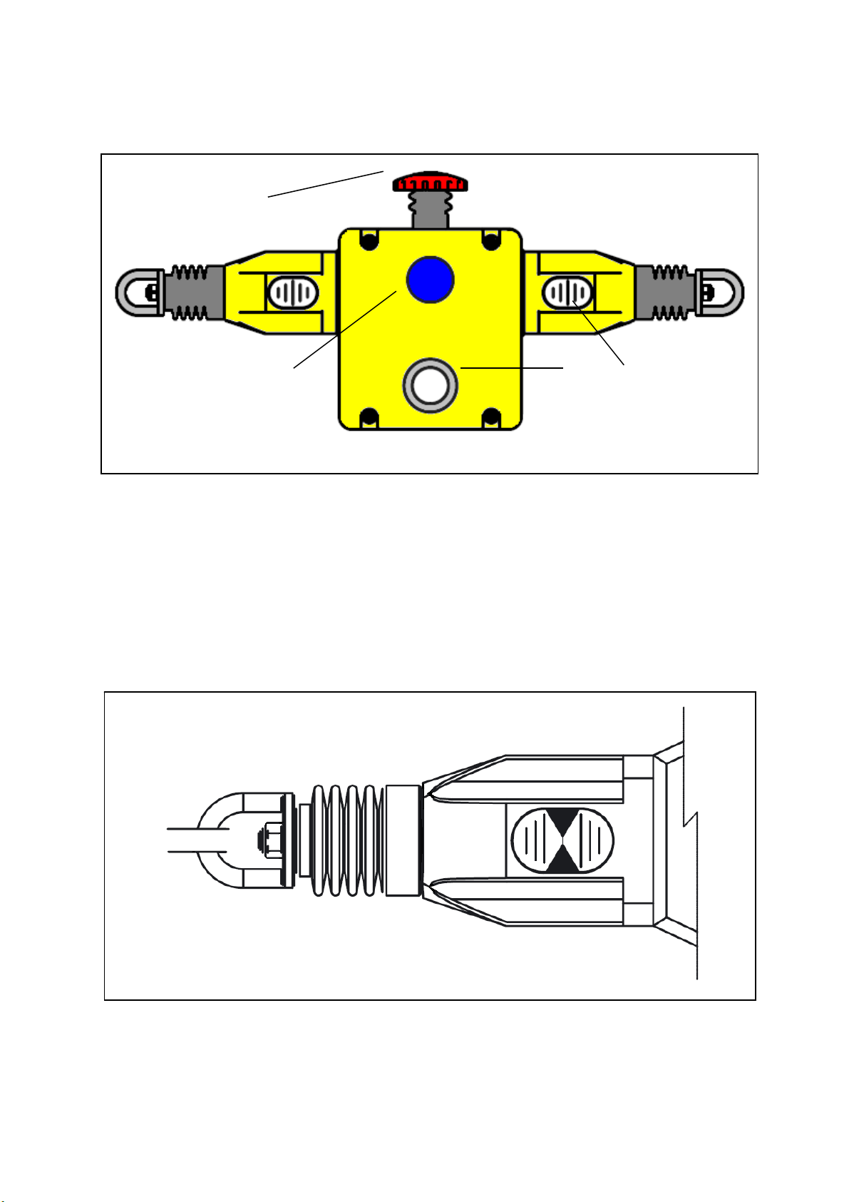
3 Operating and display elements
1: red E-stop
2: blue reset button
3: dual LED (ZB0051, ZB0070, ZB0071, ZB0075)
4: rope tension indicator
Rope tension indicator: Indicator shown with steel rope properly adjusted
5
Page 6
4 Installation
Installation must be carried out by authorised personnel. The safety rope emergency
stop switch is mounted using four M5 screws. The tightening torque for the fixing
screws is 4 Nm The tightening torque for the cover screws, the cable glands and cable
seals is 1.5 Nm to ensure protection rating IP 67. Only use seals of the correct size for
the cable entry and the external diameter of the cable.
The maximum vertical pull force on the rope pull is 130N until activation, the max.
travel 300mm. Enough space has to be provided so that the required actuation travel
can be reached.
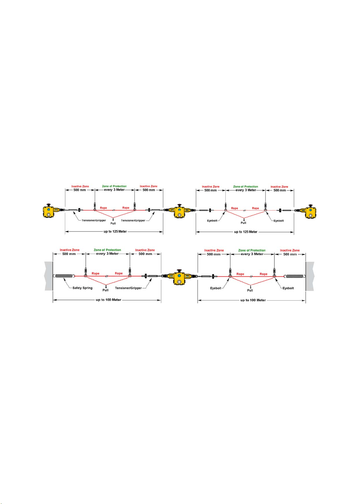
Eye bolts have to be installed between the switches across the whole length of the
rope at a distance of min. 2.5m to max. 3m. The first eyebolt must be mounted at a
distance of max. 500mm of the switch eye bolt or the tension spring (if it is used). It is
important to note that the first 500mm cannot be used as part of the active protected
area (E-stop triggering).
Installation of the components
The tension of the rope is obtained by rope tensioner systems. After the installation
the tension must be set to the middle position which is indicated by green arrows in
the transparent window of the individual switches. Verify the function of all switches
and the control circuits by pulling on various spots on the rope in the active protected
area and then resetting the individual switches by pressing the blue reset button.
Ensure each time that the switches clip into place and have to be reset manually by
pressing the blue button. If necessary, increase the rope tension until the tests along
the active length of the area are satisfactory.
6
Page 7

The switches are equipped with a red, mushroom-shaped E-stop button. Check the
individual emergency stop switches and reset them to ensure proper functioning of the
control circuits.
The typical operating conditions for a successful operation of the safety rope
emergency stop system are:
max. 75N pull force and max. 150mm bending of the rope between the eye bolts for
rope support.
Rope pull systems with single direction safety rope emergency stop switches are
influenced by fluctuations of the ambient temperature!
To ensure proper function of the rope pull system it is mandatory to take into account
the dependence on the temperature when fixing the rope length and distance of the
eye bolts (every 3m).
+ 25°C
+ 22°C
+ 20°C
+ 15°C
+ 10°C
+ 7,5°C
+ 5°C
+ 3°C
Installation Temperature [°C]
- 3°C
- 5°C
- 7,5°C
- 10°C
- 15°C
- 20°C
- 22°C
- 25°C
Rope Length 15m 30m 50m 60m 75m 100m 126m
Installation Temperature in [°C] ± X [°C] = max. allowed rope length in [m]
7
Not OK
OK
Page 8

5 Function
Pulling the tensioned rope, rope breakage or impact on the E-stop cause activation of
the switching function of the safety rope emergency stop switch.
There is a window on the switch via which the correct rope tension can be monitored
during setting and maintenance. Setting, troubleshooting and maintenance are made
much easier.
After activation of the E-stop function a latching mechanism maintains the E-stop
command until it is unlocked manually by pressing the blue reset button. Before
resetting the E-stop signal the cause of the activation has to be determined. Reset is
only possible with correct rope tension (position indication in middle position).
The max. rope length also depends on the change of the ambient temperature.
Function of the safety rope emergency stop switch
5.1 Maintenance requirement
Every week:
Check proper functioning of the system at various spots along the rope length. Check
the setting of the nominal rope tension and re-adjust it, if necessary.
Every six months:
Separate the voltage supply and remove the cover. Make sure that the screws are
tight and check them for signs of penetrated moisture.
8
Damaged or faulty devices are to be replaced! Repair is not permissible.
Page 9

6 Electrical connection
Wiring is only possible if the device is disconnected from power.
Contact arrangement
0 mm 4.0 mm 15.0 mm 17.0 mm
4 NC + 2 NO Rope slack Tension range Rope pulled
11/12
21/22
33/34
41/42
51/52
63/64
contact open contact closed
Contact travels safety rope emergency stop switch
24 V DC LED:
+ 24 V DC on terminal 1 -> LED display flashing red
+ 24 V DC on terminal 3 -> LED display permanently green
9
Page 10

Installation sample:
Programming sample:
Data bits:
Data bit
In/Out
Activated input channel Bit sequence D3-D0
SI-1 XX00
SI-2 00XX
SI-1 and SI-2 0000
keiner XXXX
Activated alarm outputs Bit sequence D3-D0
O-1 XXX1
X= random
D3 D2 D1 D0
SI-2 SI-2 SI-1 SI-1/O-1
10
Page 11

110 V AC LED:
110 V AC on terminal 1 (red) -> LED display flashing red
110 V AC on terminal 3(green) -> LED display permanently green
0V on terminal 2 (black)
Installation sample:
11
Page 12

7 Safety characteristics
Characteristics Value
Performance level PL e
Category cat. 4 (with appropriate monitoring)
MTTFd
Mission time T 21 years
Annual Usage 8 cycle per hour/24hours per day/365 days
B10d 1.5 • 106 cycles at 100mA load
These calculations were made on the basis of an ambient temperature of 40 °C.
The device meets the requirements of EN ISO 13849-1: 2008 category 4 / PL e and can be
used in applications up to PL e.
For the PFD-/PFH values and the MTTF
documentation.
Explanation of the abbreviations:
PL
Cat.
T Mission time Max. service life
Performance Level Capability of safety-related parts to
Category Classification of the safety-related parts of
214 years
values of the other components see the respective
d
perform a safety function at predictable
conditions to fulfill the expected risk
reduction.
a controller as regards their resistance to
failures.
B10d
MTTFd
Number of cycles, up to 10% of the
components with dangerous failure.
Mean Time To Dangerous
Failure
12
Page 13

8 Technical data ZB0050 / ZB0051 / ZB0071
Electrical design
Safety contacts 4 NC
Auxiliary contact 2 NO
Type of contact snap-action contacts
Contact material silver
Switching capacity AC: 240 V/3 A, 120 V/6 A, inductive
DC: 24 V/2.5 A, inductive
Max. switching voltage/switching capacity 240 V/720 VA
Minimum load 5 V, 5 mA DC
Thermal current 10 A
Rated Insulation voltage 500 V
Short-circuit / overload protection external fuse 10A (FF)
Connection terminal up to 2.5 mm 2
Mechanical design
Fixing elements 4 x M5 screws
Mounting position as required
Cable entry 4 x M20
Max. rope length 125 m each side
Activation force (on rope) < 125 N
Tension force for operating position (axial) 130 N (between switches)
Switching contacts to IEC / EN 60947-5-1
Mechanical life > 1,000,000 activations
Function display
Operation LED green
Error LED red, flashing
current load LED 15 mA
Ambient temperature -25...80 °C
Protection rating IP 67
Vibration resistance 10 - 500 Hz
Shock resistance 15g 11ms
Housing material die-cast aluminium
Housing colour yellow
Weight 1320 g
13
Page 14

8.1 Technical data ZB0070 / ZB0075
Electrical design
Safety contacts 4 NC
Auxiliary contact 2 NO
Type of contact snap-action contacts
Contact material silver
Switching capacity AC: 240 V/3 A, 120 V/6 A, inductive
DC: 24 V/2.5 A, inductive
Max. switching voltage/switching capacity 240 V/720 VA
Minimum load 5 V, 5 mA DC
Thermal current 10 A
Rated Insulation voltage 500 V
Short-circuit / overload protection external fuse 10A (FF)
Connection terminal up to 2.5 mm 2
Mechanical design
Fixing elements 4 x M5 screws
Mounting position as required
Cable entry 4 x M20
Max. rope length 125 m each side
Activation force (on rope) < 125 N
Tension force for operating position (axial) 130 N (between switches)
Switching contacts to IEC / EN 60947-5-1
Mechanical life > 1,000,000 activations
Function display
Operation LED green
Error LED red, flashing
current load LED 15 mA
Ambient temperature -25...80 °C
Protection rating IP 67
Vibration resistance 10 - 500 Hz
Shock resistance 15g 11ms
Housing material Stainless steel 316
Housing colour silver
Weight 2850 g
14
Page 15

9 Scale drawing
Dimension in mm
10 Accessories
ZB0052: Safety rope e-stop switch with left sided rope connection, LED 24 V DC
ZB0053: Safety rope e-stop switch with right sided rope connection, LED 24 V DC
ZB0072: Safety rope e-stop switch with left sided rope connection, LED 110 V AC
ZB0073: Safety rope e-stop switch with right sided rope connection, LED 110 V AC
ZB0054: Rope tensioner kit, stainless steel, rope length 5 m
ZB0055: Rope tensioner kit, stainless steel, rope length 10 m
ZB0056: Rope tensioner kit, stainless steel, rope length 20 m
ZB0057: Rope tensioner kit, stainless steel, rope length 50 m
ZB0058: Rope tensioner kit, stainless steel, rope length 80 m
ZB0059: Rope tensioner kit, stainless steel, rope length 100 m
ZB0060: Rope tensioner kit, stainless steel, rope length 126 m
ZB0061: Safety spring, stainless steel, 220 mm
ZB0062: Pulley
E7015S: Safe AS-i Safety at Work PCB
E11295: M12 adapter plug to metric M20, 4 poles
E21010: M20 x 1.5 cable gland
15
Page 16

11 Standards
The following standards and directives have been applied:
• Machinery Directive 2006/42/EC
• EN ISO 13849-1: 2008
• EN ISO 13850: 2008
• AS/NSZ 4024.1 - 2014
• IEC / EN 60947-5-1: 2004: +A1: 2009
• IEC / EN 60947-5-5: 1998 + A11: 2013
• UL 508
The device must be supplied from an electrically isolated source having a secondary
UL-listed fuse rated as noted in the following table.
Overcurrent protection
Wire cross section control circuit Maximum nominal current of the protective
Evaluation unit (mm2)
equipment
ampere
26 (0.13) 1
24 (0.20) 2
22 (0.32) 3
20 (0.52) 5
18 (0.82) 7
16 (1.3) 10
Hints for AS4024.3610-3614
Information with regard to AS4024-2014:
1) Perpendicular force to operate the switches midway between eyebolt
Supports: Check <70N. rope deflection <300mm
2) Axial force - direct along rope axis: <230N (Typical 125N).
Typical parameters for successful operation of a system is less than 70N pulling force
with less than 150mm deflection of rope between eyebolt supports. This can normally
be achieved with rope switches set to the mid position between the green arrows in
the viewing window. If required, depending upon the necessary checks along the
active length of coverage, the tension can be increased further beyond the mid
position to ensure a tripping pulling force of less than 70N.
16
Page 17

12 Approvals / certificates
• EC declaration of conformity
• TÜV Rheinland (pending)
• UL (cULus)
• AS/NSZ 4024.1
17
Page 18

ifm weltweit • ifm worldwide • ifm à l’échelle internationale
http://www.ifm.com e-mail: info@ifm.com
Service hotline: 0800 / 16 16 16 4 (only Germany, Mo-Fr from 7.00 - 18.00 h)
ifm Niederlassungen • Sales offices • Agencies
D ifm electronic gmbh Vertrieb Deutschland
Niederlassung Nord • 31135 Hildesheim • Tel. 0 51 21 / 76 67-0
Niederlassung West • 45128 Essen • Tel. 02 01 / 3 64 75 -0
Niederlassung Mitte-West • 58511 Lüdenscheid • Tel. 0 23 51 / 43 01-0
Niederlassung Süd-West • 64646 Heppenheim • Tel. 0 62 52 / 79 05-0
Niederlassung Baden-Württemberg • 73230 Kirchheim • Tel. 0 70 21 / 80 86-0
Niederlassung Bayern • 82178 Puchheim • Tel. 0 89 / 8 00 91-0
Niederlassung Ost • 07639 Tautenhain • Tel. 0 36 601 / 771-0
ifm electronic gmbh • Friedrichstraße 1 • 45128 Essen
A ifm electronic gmbh • 1120 Wien • Tel. +43 16 17 45 00
AUS ifm efector pty ltd. • Mulgrave Vic 3170 • Tel. +61 3 00 365 088
B L ifm electronic N.V. • 1731 Zellik • Tel. +32 2 / 4 81 02 20
BR ifm electronic Ltda. • 03337-000, Sao Paulo SP • Tel. +55 11 / 2672-1730
CH ifm electronic ag • 4 624 Härkingen • Tel. +41 62 / 388 80 30
CL ifm electronic SpA • Oficina 5032 Comuna de Conchalí • Tel. +56 232 239 282
CN ifm electronic Co. Ltd. • 201210 Shanghai • Tel. +86 21 / 3813 4800
CND ifm efector Canada inc. • Oakville, Ontario L6K 3V3 • Tel. +1 800-441-8246
CZ ifm electronic spol. s.r.o. • 25243 Průhonice • Tel. +420 267 990 211
DK ifm electronic a/s • 2605 BROENDBY • Tel. +45 70 20 11 08
E ifm electronic s.a. • 08820 El Prat de Llobregat • Tel. +34 93 479 30 80
F ifm electronic s.a. • 93192 Noisy-le-Grand Cedex • Tél. +33 0820 22 30 01
FIN ifm electronic oy • 00440 Helsinki • Tel . +358 75 329 5000
GB IRL ifm electronic Ltd. • Hampton, Middlesex TW12 2HD • Tel. +44 208 / 213-0000
GR ifm electronic Monoprosopi E.P.E. • 15125 Amaroussio • Tel. +30 210 / 6180090
H ifm electronic kft. • 9028 Györ • Tel. +36 96 / 518-397
I ifm electronic s.a. • 20041 Agrate-Brianza (MI) • Tel. +39 039 / 68.99.982
IL Astragal Ltd. • Azur 58001 • Tel. +972 3 -559 1660
IND ifm electronic India Branch Office • Kolhapur, 416234 • Tel. +91 231-267 27 70
J efector co., ltd. • Chiba-shi, Chiba 261-7118 • Tel. +81 043-299-2070
MAL ifm electronic Pte. Ltd • 47100 Puchong Selangor • Tel. +603 8063 9522
MEX ifm efector S. de R. L. de C. V. • Monterrey, N. L. 64630 • Tel. +52 81 8040-3535
N Sivilingeniør J. F. Knudtzen A/S • 1396 Billingstad • Tel. +47 66 / 98 33 50
NA ifm electronic (pty) Ltd • 25 Dr. W. Kulz Street Windhoek • Tel. +264 61 300984
NL ifm electronic b.v. • 3843 GA Harderwijk • Tel. +31 341 / 438 438
NZ ifm efector pty ltd • 930 Great South Road Penrose, Auckland • Tel. +64 95 79 69 91
P ifm electronic s.a. • 4410-136 São Félix da Marinha • Tel. +351 223 / 71 71 08
PL ifm electronic Sp. z o.o. • 40-524 Katowice • Tel. +48 32-608 74 54
RA ROU ifm electronic s.r.l. • 1107 Buenos Aires • Tel. +54 11
ROK ifm electronic Ltd. • 140-884 Seoul • Tel. +82 2 / 790 5610
RUS ifm electronic • 105318 Moscow • Tel. +7 495 921-44-14
S ifm electronic a b • 512 60 Överlida • Tel. +46 325 / 661 500
SGP ifm electronic Pte. Ltd. • Singapore 609 916 • Tel. +65 6562 8661/2/3
SK ifm electronic s.r.o. • 835 54 Bratislava • Tel. +421 2 / 44 87 23 29
THA Sang Chai Meter Co., Ltd. • Bangkok 10 400 • Tel. +66 2 / 616 80 51
TR ifm electronic Ltd. Sti. • 34381 Sisli/Istanbul • Tel. +90 212 / 210 50 80
UA TOV ifm electronic • 02660 Kiev • Tel. +380 44 501 8543
USA ifm efector inc. • Exton, PA 19341 • Tel. +1 610 / 5 24-2000
VN ifm electronic • Ho Chi Minh City 700000 • Tel. +84-8-35125177
ZA ifm electronic (Pty) Ltd. • 0157 Pretoria • Tel. +27 12 450 0400
/ 5353 3436
Technische Änderungen behalten wir uns ohne vorherige Ankündigung vor. • We reserve the right to make technical alterations without prior notice. • Nous nous réservons le droit de modifier les données techniques sans préavis.
18
 Loading...