

Page 1
Bedienungsanleitung
Operating instructions
Notice utilisateurs
Auswerteelektronik für
Strömungssensoren
Evaluation system for
flow sensors
Boîtier de contrôle pour
sondes de débit
VS3000
DEUTSCHENGLISHFRANÇAIS
Sachnr. 704036/01 02/06
R
Page 2

2
Inhalt
Sicherheitshinweise . . . . . . . . . . . . . . . . . . . . . . . . . . . . . . Seite 3
Bestimmungsgemäße Verwendung . . . . . . . . . . . . . . . . . . . Seite 4
Montage . . . . . . . . . . . . . . . . . . . . . . . . . . . . . . . . . . . . . . Seite 4
Elektrischer Anschluß . . . . . . . . . . . . . . . . . . . . . . . . . . . . . Seite 5
Einstellen . . . . . . . . . . . . . . . . . . . . . . . . . . . . . . . . . . . . . Seite 7
Funktionsdiagramm Strömungsüberwachung . . . . . . . . . . . Seite 8
Inbetriebnahme / Betrieb . . . . . . . . . . . . . . . . . . . . . . . . . . Seite 8
Wartung, Instandsetzung, Entsorgung . . . . . . . . . . . . . . . . Seite 8
Technische Daten . . . . . . . . . . . . . . . . . . . . . . . . . . . . . . . Seite 9
Maßzeichnung . . . . . . . . . . . . . . . . . . . . . . . . . . . . . . . . .Seite 26
Die Bedienungsanleitung
... gilt für alle Geräte des Typs VS3000 im Tragschienengehäuse. Die
einzelnen Geräte unterscheiden sich nur in der Art der Versorgungsspannung. Sie ist auf dem Typenschild des Geräts angegeben.
Es stehen 2 Versionen zur Verfügung: 24 VDC und 85 bis 265 VAC.
... ist Bestandteil des Geräts. Sie enthält Angaben zum korrekten
Umgang mit dem Produkt. Lesen Sie sie vor dem Einsatz, damit Sie mit
Einsatzbedingungen, Installation und Betrieb vertraut werden.
Befolgen Sie die Sicherheitshinweise. Die Anleitung richtet sich an
fachkundige Personen im Sinne von EMV- und der NiederspannungsRichtlinie.
Page 3
3
DEUTSCH
Sicherheitshinweise
Befolgen Sie die Angaben der Bedienungsanleitung.
Nichtbeachten der Hinweise, Verwendung außerhalb der
nachstehend genannten bestimmungsgemäßen Verwendung,
falsche Installation oder Handhabung können
Beeinträchtigungen der Sicherheit von Menschen und
Anlagen zur Folge haben.
Das Gerät darf nur von einer Elektrofachkraft eingebaut,
angeschlossen und in Betrieb gesetzt werden, da bei der
Installation berührungsgefährliche Spannungen auftreten
können. Die sichere Funktion des Geräts und der Anlage ist
nur bei ordnungsgemäßer Installation gewährleistet.
Schalten Sie das Gerät extern spannungsfrei bevor Sie irgendwelche Arbeiten an ihm vornehmen. Schalten Sie ggf. auch
unabhängig versorgte Relais-Lastkreise ab.
Vorsicht bei Bedienung im eingeschalteten Zustand. Sie ist
aufgrund der Schutzart IP 20 nur durch Fachkräfte zulässig.
Die Gerätekonstruktion entspricht Schutzklasse II (EN61010)
vorbehaltlich des Klemmenbereichs. In diesem ist erst bei vollständig aufgesteckten Klemmen ein Schutz gegen zufälliges
Berühren (Fingersicherheit nach IP20) für die Bedienung durch
Fachpersonal gegeben. Deshalb ist das Gerät immer in einem
nur mit Werkzeug zu öffnenden Schaltschrank der
Mindestschutzart IP 54 zu installieren.
Bei DC-Geräten muß die externe 24 V-Gleichspannung gemäß
den Kriterien für sichere Kleinspannung (SELV) erzeugt und
zugeführt werden, da diese Spannung ohne weitere
Maßnahmen in der Nähe der Bedienelemente und an den
Klemmen für die Speisung angeschlossener Sensoren zur
Verfügung gestellt wird.
Bei Fehlfunktion des Geräts oder bei Unklarheiten setzen Sie
sich bitte mit dem Hersteller in Verbindung. Eingriffe in das
Gerät können schwerwiegende Beeinträchtigungen der
Sicherheit von Menschen und Anlagen zur Folge haben. Sie
sind nicht zulässig und führen zu Haftungs- und
Gewährleistungsauschluss.
Page 4
Die Auswerteelektronik VS3000 ist konzipiert für den Anschluß von
Strömungssensoren des Typs SFxxxx. Sie wertet die Signale der
Sensoren aus und meldet, ob ein voreingestellter Strömungswert
erreicht ist:
• Strömung oberhalb des voreingestellten Werts / Ausgangsrelais ist
angezogen.
• Strömung unterhalb des voreingestellten Werts / Ausgangsrelais ist
abgefallen.
• Wahlweise Überwachung flüssiger oder gasförmiger Strömungen.
• Überwachung der Sensorleitung: Bei Leitungsbruch oder
Kurzschluss fällt das Überwachungsrelais ab, die rote LED (WIRE
BREAK/RELAY) leuchtet.
• Temperaturüberwachung: Bei Überschreiten der eingestellten
Temperatur zieht das Relais an, die rote LED (TEMP/RELAY) leuchtet.
Das Gerät ist nicht für sicherheitsrelevante Aufgaben im Sinne
des Personenschutzes zugelassen.
Bauen Sie das Gerät in einen Schaltschrank der Mindestschutzart IP 54
ein, um Schutz vor unbeabsichtigtem Kontakt mit berührungsgefährlichen Spannungen und vor atmosphärischen Einflüssen zu gewährleisten. Der Schaltschrank sollte in Übereinstimmung mit den
Vorschriften der lokalen und nationalen Bestimmungen installiert werden.
Montieren Sie das Gerät an eine Tragschiene. Montieren Sie es senkrecht und lassen Sie ausreichend Platz zu Boden oder Deckel des
Schaltschranks (um Luftzirkulation zu ermöglichen und übermäßige
Erwärmung zu vermeiden).
Verhindern Sie das Eindringen von leitfähiger oder sonstiger
Verschmutzung bei der Montage oder den Verdrahtungsarbeiten.
Montage der Sensoren:
Befolgen Sie die Hinweise der Montageanleitung, die dem Sensor beiliegt.
4
Bestimmungsgemäße Verwendung
Montage
Page 5
Das Gerät darf nur von einer Elektrofachkraft installiert werden.
Befolgen Sie die nationalen und internationalen Vorschriften zur
Errichtung elektrotechnischer Anlagen.
Vermeiden Sie den Kontakt mit berührungsgefährlichen
Spannungen.
Schalten Sie vor dem Verdrahten die Anlage spannungsfrei!
Achten Sie speziell auf andere Stromkreise an den Relais.
Um Funktionsbeeinträchtigungen durch Störspannungen zu vermeiden, sollten Sensorkabel und Lastkabel getrennt voneinander verlegt
werden. Maximale Länge des Sensorkabels: 100m.
Anschluss durch Combiconstecker (vormontiert).
Combiconstecker sind auch als Zubehör lieferbar:
•
Stecker mit Käfigzugfederklemmen (Bestell-Nr. E40171),
• Stecker mit Schneidklemmen (Bestell-Nr. E40172),
• Stecker mit Schraubklemmen (Bestell-Nr. E40173).
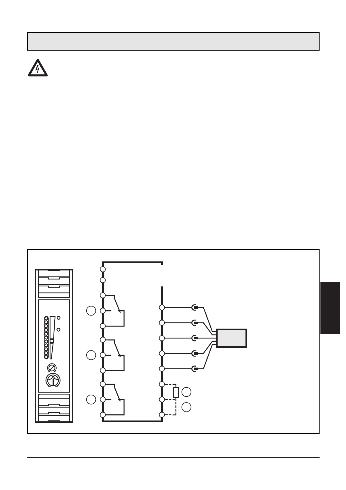
Klemmenbelegung:
5
DEUTSCH
1: Strömungsüberwachung
2: Leitungsüberwachung
3: Temperaturüberwachung
4:
Bereitschaftsverzögerungszeit
5: Wahl flüssig / gasförmig
Adernfarben bei Strömungssensoren des Tys SFxxxx:
BN = braun, BU = blau, BK = schwarz, WH = weiß, GY = grau
Elektrischer Anschluß
1234
5678
9 101112
LOW VOLTAGE
WIRE BREAK-
RELAY
TEMPRELAY
SWITCH
FLOW
POINTRELAY
FLOW
TEMP
17 18 19 20
21 22 23 24
1
2
3
1
2
4
5
6
7
8
9
10
11
12
: L (AC) / L+ (DC)
: N (AC) / L- (DC)
17
18
19
20
21
22
23
24
WH
BU
BN
BK
GY
2
3
1
4
5
4
5
Page 6

Spannungsversorgung (Power)
Klemme 1: L (AC-Gerät) / L+ (DC-Gerät),
Klemme 2: N (AC-Gerät) / L- (DC-Gerät).
Bei DC-Geräten muß die Versorgungsspannung extern abgesichert
sein (max. 2A).
Die Klemmen der DC-Versorgung sind direkt mit den Klemmen der
Sensorversorgung verbunden. Daher müssen für DC-Versorgung die
SELV-Kriterien eingehalten werden (Schutzkleinspannung, Stromkreis
galvanisch getrennt von anderen Stromkreisen, nicht geerdet).
Soll der DC-Kreis geerdet werden (z. B. aufgrund nationaler
Vorschriften), müssen die PELV-Kriterien eingehalten werden
(Schutzkleinspannung, Stromkreis galvanisch getrennt von anderen
Stromkreisen).
Wird das Gerät AC versorgt, so genügt die für die Sensorversorgung
intern erzeugte Kleinspannung den SELV-Kriterien.
Anschluss der Sensoren
Halten Sie auch beim Anschluss der Sensoren die SELV-Kriterien ein,
damit am Sensor keine berührungsgefährlichen Spannungen anliegen
oder diese in das Gerät verschleppt werden!
Relaisausgänge
Die Spannung zwischen den unterschiedlichen Ausgangsstromkreisen
(Klemmen 4, 5, 6 zu Klemmen 7, 8, 9 zu Klemmen 10, 11, 12) darf
den zulässigen Maximalwert von 300 V AC nicht überschreiten.
6
Page 7
1. Wahl des überwachten Mediums:
Auslieferungszustand: Überwachung flüssiger Medien. Zur Überwachung gasförmiger Medien: Klemmen 23 / 24 brücken.
2. Einstellen der Bereitschaftsverzögerungszeit:
Auslieferungszustand: Bereitschaftsverzögerungszeit = 10s. Zum
Festlegen anderer Zeiten t1: Externen Widerstand (R) zwischen den
Klemmen 22 und 23 anschließen.
3. Betriebsspannung einschalten. Nach Ablauf der Bereitschaftsverzögerungszeit ist das Gerät betriebsbereit; (während dieser Zeit
ist das Ausgangsrelais angezogen).
4. Medium mit der gewünschten Maximalströmung in der Anlage
fließen lassen. Einstellpotentiometer (2) drehen, bis eine grüne LED
leuchtet. Je weiter die grün aufleuchtende LED von der gelben LED
entfernt ist, desto sicherer ist der Abgleich (Betriebsreserve für
Strömungs- oder Temperaturschwankungen).
5. Einstellpotentiometer für Temperaturüberwachung (3) auf die gewünschte Grenztemperatur einstellen.
7
DEUTSCH
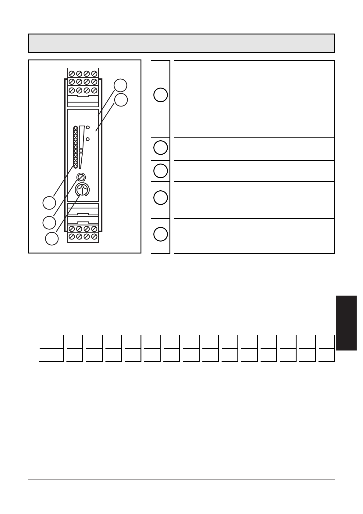
Potentiometer (Schaltpunkt Strömung)
LED-Kette
- rote LED leuchtet: Strömung unterhalb
des Schaltpunkts
- gelbe LED leuchtet: Relais angezogen,
Strömung hat den Schaltpunkt erreicht
- grüne LED leuchtet: Strömung oberhalb des Schaltpunkts
Potentiometer (Schaltpunkt Temperatur)
LED rot (TEMP/RELAY): leuchtet bei
Überschreitung der eingestellten
Mediumtemperatur
LED rot (WIRE BREAK/RELAY): leuchtet
bei Leitungsbruch oder Kurzschluss der
Sensorleitungen
1
2
3
4
5
Einstellen
t1 [s] 15 20 25 30 35 40 45 50 55 60 65 70 75 80
R [kΩ]
10 18 27 39 47 56 68 82
100
120 150 180 220 270
1
2
3
FLOW
LOW VOLTAGE
WIRE BREAK-
RELAY
TEMPRELAY
SWITCH
POINTRELAY
FLOW
TEMP
4
5
Page 8
Prüfen Sie nach Montage, Verdrahtung und Einstellung, ob das Gerät
sicher funktioniert.
Bei Leitungsbruch oder Kurzschluß fällt das Relais
“Leitungsüberwachung” ab und die rote LED (WIRE BREAK/RELAY)
leuchtet. Nach Behebung der Störung ist das Gerät wieder betriebsbereit.
Bei sachgemäßem Betrieb sind keine Maßnahmen für Wartung und
Instandhaltung notwendig.
Abhängig von der zu erwartenden Schalthäufigkeit und der zu schaltenden Last, ist eine regelmäßige Prüfung der Relais-Kontakte angeraten.
Das Gerät darf nur vom Hersteller repariert werden.
Entsorgen Sie das Gerät nach Gebrauch umweltgerecht gemäß den
gültigen nationalen Bestimmungen.
8
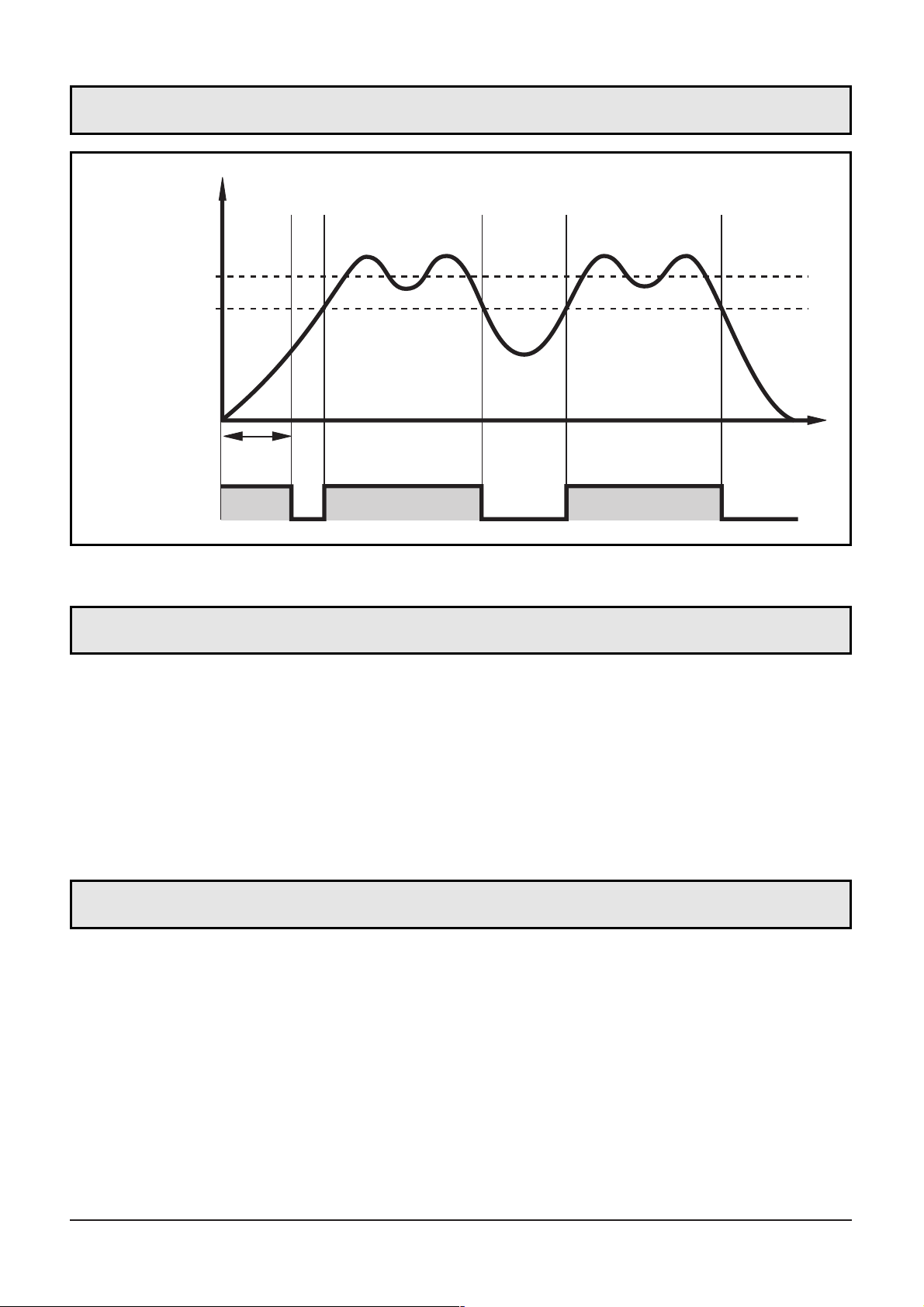
Sollströmung
Schaltpunkt
Ausgangsrelais
t1 = Bereitschaftsverzögerungszeit
Funktionsdiagramm Strömungsüberwachung
Inbetriebnahme / Betrieb
Wartung, Instandsetzung, Entsorgung
f
t1
1
0
t
Page 9

Technische Daten
9
DEUTSCH
AC
Nennspannung [V] . . . . . . . . . . . . . . . . . . . . . . . . 90...240 AC (47...63 Hz)
Spannungstoleranz [%] . . . . . . . . . . . . . . . . . . . . . . . . . . . . . . . . -5 / +10
Leistungsaufnahme max. [VA] . . . . . . . . . . . . . . . . . . . . . . . . . . . . . . . . . 4
DC
Betriebsspannung [V] . . . . . . . . . . . . . . . . . . . . . . . . . . . . . . . . . . . 24 DC
Spannungstoleranz [%] . . . . . . . . . . . . . . . . . . . . . . . . . . . . . . . . . . +/-10
Stromaufnahme [mA] . . . . . . . . . . . . . . . . . . . . . . . . . . . . . . . . . . . . . 90
Relais:
- Kontaktbelastbarkeit . . . . . . . . . . . . . . . . . . . . . 4 A (250 VAC / 30 VDC)
Strömungsüberwachung
- Schaltfunktion . . . . . . . . . . . . . . . . . . . . . . . . . . . Relais ist bei Strömung
und während der Bereitschaftsverzögerungszeit angezogen
- Optische Funktionsanzeige . . . . . . . . . . . . . . . . . . . . . . . . . . . . . .11 LED
- Schaltpunktabgleich . . . . . . . . . . . . . . . . . . . . . . . . . . . . . Potentiometer
- Bereichswahl flüssig / gasförmig . . . . . . . . . . Drahtbrücke Klemmen 23-24
Temperaturüberwachung
- Schaltfunktion . . . . . . . . . . . Relais zieht bei Temperaturüberschreitung an
- Schaltzustandsanzeige . . . . . . . . . . . . . . . . . . . . . . . . . . . . . . . . . LED rot
- Temperaturbereich [°C] . . . . . . . . . . . . . . . . . . . . . . . . . . . . . . . . . 0...80
- Reproduzierbarkeit des eingestellten Schaltpunktes [°C] . . . . . . . . . . . ± 4
Leitungsüberwachung
- Schaltfunktion . . . . . . . . Relais fällt bei Leitungsbruch oder Kurzschluss ab
- Schaltzustandsanzeige . . . . . . . . . . . . . . . . . . . . . . . . . . . . . . . . . LED rot
- Ansprechzeit [s] . . . . . . . . . . . . . . . . . . . . . . . . . . . . . . . . . . . . . . max. 3
Bereitschaftsverzögerungszeit [s] . . . . . . . . . . . . . . . . . . . . . . . . .10...80 *)
Umgebungstemperatur [°C] . . . . . . . . . . . . . . . . . . . . . . . . . . . -20 ... +60
Schutzart . . . . . . . . . . . . . . . . . . . . . . . . . . . . . . . . . . . . . . . . . . . . IP 20
Schutzklasse
- AC . . . . . . . . . . . . . . . . . . . . . . . . . . . . . . . . . . . . . . . . . . . . . . . . . . . II
- DC . . . . . . . . . . . . . . . . . . . . . . . . . . . . . . . . . . . . . . . . . . . . . . . . . . . III
Gehäusewerkstoffe . . . . . . . . . . . . . . . . . . . . . . . . . . . . . . . . . . . . . . . PA
*) einstellbar (Festwiderstände Klemmen 22-23)
Page 10

10
Contents
Safety instructions . . . . . . . . . . . . . . . . . . . . . . . . . . . . . . page 11
Function and features . . . . . . . . . . . . . . . . . . . . . . . . . . . page 12
Mounting . . . . . . . . . . . . . . . . . . . . . . . . . . . . . . . . . . . . page 12
Electrical connection . . . . . . . . . . . . . . . . . . . . . . . . . . . . page 13
Adjustment . . . . . . . . . . . . . . . . . . . . . . . . . . . . . . . . . . . page 15
Function diagram flow monitoring . . . . . . . . . . . . . . . . . . page 16
Commissioning / operation . . . . . . . . . . . . . . . . . . . . . . . page 16
Maintenance, repair, disposal . . . . . . . . . . . . . . . . . . . . . . page 16
Technical data . . . . . . . . . . . . . . . . . . . . . . . . . . . . . . . . . page 17
Scale drawing . . . . . . . . . . . . . . . . . . . . . . . . . . . . . . . . .page 26
The operating instructions
... apply to all control monitors of type VS3000 for 35mm DIN rail
mounting. The only difference between the individual units is the type
of supply voltage which is indicated on the type label of the unit.
2 versions are available: 24 V DC and 85 to 265 V AC.
... are part of the unit. They contain information about the correct handling of the product. Read them before use to get familiar with operating conditions, mounting and operation. Adhere to the safety
instructions. The operating instructions are made for authorised persons according to the EMC and low voltage guidelines.
Page 11

11
ENGLISH
Safety instructions
Follow the operating instructions, as failure to do so may
result in damage to both the unit and persons using the
equipment.
Ensure that the unit is isolated from any supply voltages
before installing or changing the equipment. Installation
should only be carried out by qualified personnel (due to the
IP 20 rating). When altering the settings of the units please
ensure that the unit is not connected to the monitored plant.
The design of the units corresponds to protection class II
(EN61010) except for the terminal blocks where protection
against accidental contact (safety from finger-touch to IP 20)
for operation by qualified staff is only guaranteed if the terminals are completely inserted. This is why the unit always
has to be mounted in a control cabinet of at least IP 54 which
can only be opened by means of keys.
If the unit has an external 24 V DC supply, this voltage has to
be generated and supplied externally according to the
requirements for safe extra-low voltage (SELV) since without
further measures this voltage is supplied near the operating
elements and at the terminals for the supply of connected
pulse pick-ups.
In case of malfunctioning of the unit or uncertainties please
contact the manufacturer. An unauthorised access of the unit
can lead to considerable risks for the safety of persons and
plant. It is not permitted and leads to an exclusion of liability
and warranty.
Page 12

The evaluation system VS3000 is designed to work with flow sensors
of the type SFxxxx. It evaluates the signals from the sensors and signals whether there is a preset flow rate or not:
• Flow above the preset value / output relay is energised
• Flow below the preset value / output relay is de-energised
• Flows of either liquids or gases can be monitored.
• Wire break monitoring: in the case of an open-circuit or short-circuit the monitoring relay is de-energised, the red LED (WIRE
BREAK/RELAY) signals a fault.
• Temperature monitoring: relay is energised when temperature is
exceeded, the red LED (TEMP/RELAY) signals a fault.
The unit is not approved for safety tasks in the field of safety of
persons.
Mount the unit in a control cabinet with a protection rating of at least
IP 54 to guarantee protection against accidental contact with voltages
and against atmospheric influence. The control cabinet should be
installed in accordance with local and national rules and regulations.
Mount the unit on a DIN rail Once mounted leave enough space
between the unit and the top and bottom of the control cabinet (to
enable air circulation and to avoid excessive heating).
Prevent the penetration of conductive or other dirt into the housing or
wiring.
Mounting of the sensors:
Adhere to the mounting instructions of the manufacturer.
12
Function and features
Mounting
Page 13

The unit must only be connected by an electrician.
The national and international regulations for the installation of
electrical equipment must be observed.
Avoid contact with voltages.
Disconnect the plant from power before wiring. Check if the
relays are connected to voltages of external power supplies.
In order to avoid malfunction caused by interference, lay the sensor
cable separately from the load cable. Max. length of the sensor cable:
100m.
Connection by means of Combicon connectors (fitted).
Combicon connectors are also available as accessories:
• connector with cage clamps (order no. E40171),
• connector with insulation displacement terminals (order no. E40172),
• Connector with screw terminals (order no. E40173).
Terminal connection:
13
ENGLISH
1: flow monitoring
2: wire break monitoring
3: temperature monitoring
4:
power-on delay time
5: selection liquid / gas
Core colours for flow sensors of the type SFxxxx:
BN = brown, BU = blue, BK = black, WH = white, GY = grey
Electrical connection
1
1234
5678
9101112
LOW VOLTAGE
WIRE BREAK-
RELAY
TEMPRELAY
SWITCH
FLOW
POINTRELAY
FLOW
TEMP
17 18 19 20
21 22 23 24
1
2
3
: L (AC) / L+ (DC)
: N (AC) / L- (DC)
2
4
5
6
7
8
9
10
11
12
17
18
19
20
21
22
23
24
WH
BU
BN
BK
GY
2
3
1
4
5
4
5
Page 14

Power supply (Power)
Terminal 1: L (AC unit) / L+ (DC unit).
Terminal 2: N (AC unit) / L- (DC unit).
For DC units the supply voltage must be protected externally (max.
2A).
The terminals of the DC supply are directly linked with the terminals
of the sensor supply. This is why the SELV criteria must be adhered to
for DC supply (protective low voltage, circuit galvanically separated
from other circuits, not earthed).
If the DC circuit is to be earthed (e.g. because of national regulations),
the PELV criteria have to be adhered to (protective low voltage, circuit
galvanically separated from other circuits).
If the unit is supplied with AC voltage, the low voltage supply for the
sensors meets the SELV criteria.
Connection of sensors
Please also adhere to the SELV criteria for the sensor connection so
that there is no dangerous contact voltage at the sensor which can
enter the unit!
Relay outputs
The voltage between the different output circuits (terminals 4, 5, 6 –
terminals 7, 8, 9 – terminals 10, 11, 12) must not exceed the permissible maximum value of 300 V AC.
14
Page 15

1. Selection of the monitored medium:
Factory setting: Monitoring of liquids. For monitoring of gases: Link
terminals 23 / 24.
2. Setting of the power-on delay time:
Factory setting: Power-on delay time = 10 s. To define other times
for t1: Connect an external resistor (R) between the terminals 22
and 23.
3. Apply the operating voltage. After the power-on delay time has
elapsed, the unit is ready for operation, (during this time the output relay is energised).
4. Set the preset flow and keep it constant. Turn the setting poten-
tiometer (2) until a green LED lights. The farther the green LED lit is
away from the yellow LED, the safer is the adjustment (excess gain
for flow or temperature fluctuations).
5. Set the setting potentiometer for the temperature monitoring (3) to
the requested limit temperature.
15
ENGLISH
Potentiometer (switch point flow)
Bank of LED's
- red LED lit: flow below the switch
point
- yellow LED lit: relay is energised, flow
has reached the switch point
- green LED lit: flow above the switch
point
Potentiometer (switch point
temperature)
Red LED (TEMP/RELAY): lights if the set
temperature is exceeded
Red LED (WIRE BREAK/RELAY): lights in
case of wire break or short circuit of the
sensor wires
1
2
3
4
5
Adjustment
t1 [s] 15 20 25 30 35 40 45 50 55 60 65 70 75 80
R [kΩ]
10 18 27 39 47 56 68 82
100
120 150 180 220 270
LOW VOLTAGE
WIRE BREAK-
RELAY
TEMPRELAY
SWITCH
FLOW
POINTRELAY
4
5
FLOW
TEMP
1
2
3
Page 16

After mounting, wiring and setting check whether the unit operates
correctly.
For units with monitoring of the sensor cable: In the case of wire break
or short circuit the relay "wire monitoring" is de-energised and the red
LED lights. After rectification of the fault the control monitor is again
ready for operation.
In case of correct use no maintenance measures are necessary.
Depending on the switching rate to be expected and the load to be
switched, we recommend testing the relay contacts.
Only the manufacturer is allowed to repair the unit.
After use dispose of the unit in an environmentally friendly way
according to the valid national regulations.
16
preset flow
switch point
output
relay
t1 = power-on delay time
Function diagram flow monitoring
Commissioning / operation
Maintenance, repair, disposal
f
t1
1
0
t
Page 17

Technical data
17
ENGLISH
AC:
Nominal voltage [V] . . . . . . . . . . . . . . . . . . . . . . . 90...240 AC (47...63 Hz)
Voltage tolerance [%] . . . . . . . . . . . . . . . . . . . . . . . . . . . . . . . . . -5 / +10
Power consumption max. [VA] . . . . . . . . . . . . . . . . . . . . . . . . . . . . . . . . 4
DC:
Operating voltage [V] . . . . . . . . . . . . . . . . . . . . . . . . . . . . . . . . . . . 24 DC
Voltage tolerance [%] . . . . . . . . . . . . . . . . . . . . . . . . . . . . . . . . . . . +/-10
Current consumption [mA] . . . . . . . . . . . . . . . . . . . . . . . . . . . . . . . . . 90
Relais:
- Contact rating . . . . . . . . . . . . . . . . . . . . . . . . . 4 A (250 VAC / 30 VDC)
Flow monitoring
- Switching function . . . . . . . . . . . . . . relay energised when flow is present
and during the power-on delay time
- Function display . . . . . . . . . . . . . . . . . . . . . . . . . . . . . . . . . . . . . .11 LED
- Adjustment of the switch point . . . . . . . . . . . . . . . . . . . . . . . . . with pot.
- Selection liquids / gases . . . . . . . . . . . . . . . . . . . . . . link terminals 23-24
Temperature monitoring
- Switching functio . . . . . . . relay energised when temperature is exceeded
- Output status indication . . . . . . . . . . . . . . . . . . . . . . . . . . . . . . . LED red
- Temperature range [°C] . . . . . . . . . . . . . . . . . . . . . . . . . . . . . . . . . 0...80
- Repeatability switch point / measured value [°C] . . . . . . . . . . . . . . . . . ± 4
Wire break monitoring
- Switching function . . . . . . . . . . . relay de-energised in case of wire break
or short circuit
- Output status indication . . . . . . . . . . . . . . . . . . . . . . . . . . . . . . . LED red
- Response time [s] . . . . . . . . . . . . . . . . . . . . . . . . . . . . . . . . . . . . . max. 3
Power-on delay time [s] . . . . . . . . . . . . . . . . . . . . . . . . . . . . . . .10...80 *)
Operating temperature [°C] . . . . . . . . . . . . . . . . . . . . . . . . . . . -20 ... +60
Protection . . . . . . . . . . . . . . . . . . . . . . . . . . . . . . . . . . . . . . . . . . . . IP 20
Protection class
- AC . . . . . . . . . . . . . . . . . . . . . . . . . . . . . . . . . . . . . . . . . . . . . . . . . . . II
- DC . . . . . . . . . . . . . . . . . . . . . . . . . . . . . . . . . . . . . . . . . . . . . . . . . . . III
Housing material . . . . . . . . . . . . . . . . . . . . . . . . . . . . . . . . . . . . . . . . . PA
*) adjustable (fixed-value resistors terminals 22-23)
Page 18

18
Contenu
Remarque sur la sécurité . . . . . . . . . . . . . . . . . . . . . . . . . page 19
Fonctionnement et caractéristiques . . . . . . . . . . . . . . . . . . page 20
Montage . . . . . . . . . . . . . . . . . . . . . . . . . . . . . . . . . . . . page 20
Raccordement électrique . . . . . . . . . . . . . . . . . . . . . . . . . page 21
Réglage . . . . . . . . . . . . . . . . . . . . . . . . . . . . . . . . . . . . . page 23
Diagramme fonction, surveillance du débit . . . . . . . . . . . . page 24
Mise en service / fonctionnement . . . . . . . . . . . . . . . . . . . page 24
Maintenance, réparation, élimination . . . . . . . . . . . . . . . . page 24
Données techniques . . . . . . . . . . . . . . . . . . . . . . . . . . . . page 25
Dimensions . . . . . . . . . . . . . . . . . . . . . . . . . . . . . . . . . . .page 26
La notice utilisateurs
... s'applique à tous les boîtiers de type VS3000 pour le montage sur
profilé selon les normes. Les différents types de boîtiers se différencient
par la tension d'alimentation. Elle est indiquée sur l'étiquette du
boîtier. 2 versions sont disponibles : 24 V DC et 85 à 265 V AC.
... fait partie de l'appareil. Elle fournit des informations sur la manipulation correcte du produit. Lisez-la avant l'emploi afin que vous vous
familiarisiez avec les conditions environnantes, l'installation et le
fonctionnement. Respectez les remarques sur la sécurité. La notice
s'adresse à des personnes compétentes selon les directives CEM et
basse tension.
Page 19

19
FRANÇAIS
Remarque sur la sécurité
Respectez les indications de la notice utilisateurs. La sécurité
des personnes et des installations peut être atteinte en cas de
non-respect des remarques, d'emploi non conforme aux prescriptions, de montage ou manipulation incorrect.
L'appareil ne doit être monté, raccordé et mis en service que
par un électricien car des tensions dangereuses au contact
peuvent se produire lors du montage. Le fonctionnement sûr
de l'appareil et de l'installation n'est garanti qu'en cas de
montage correct.
Mettez l'appareil hors tension en externe avant de le manipuler. Le cas échéant, mettez également hors tension les circuits
des charges relais alimentés séparément.
Faites attention lors de la manipulation de l'appareil sous tension. En raison de la protection IP 20 ceci n'est permis que par
le personnel compétent.
La construction de l'appareil est conforme à la classe de protection II (EN61010) sauf l'espace autour des bornes. La protection contre le contact accidentel (protection contre le
contact du doigt selon IP20) pour le personnel lors de la manipulation de l'appareil n'est assurée qu'en cas de bornes complètement fixées. De ce fait, l'appareil doit toujours être installé dans une armoire électrique de protection minimale IP54
qui ne peut être ouverte qu'à l'aide d'un outil.
Pour des appareils DC l'alimentation 24 V DC externe doit être
générée et fournie selon les critères de la basse tension de
sécurité (SELV) parce que cette tension est disponible sans plus
de mesures de protection près des éléments de service et sur
les bornes pour l'alimentation des sondes raccordées.
En cas de mauvais fonctionnement de l'appareil ou en cas de
doute prenez contact avec le fabricant. Des interventions sur
l'appareil peuvent avoir des conséquences graves pour la
sécurité des personnes et des installations. Elles ne sont pas
permises et aboutissent à une exclusion de responsabilité et
de garantie.
Page 20

Le VS3000 est prévu pour le raccordement des sondes de débit SFxxxx.
Il évalue les signaux des sondes et indique si une valeur de débit
présélectionnée est atteinte ou non.
• Débit au-dessus de la valeur présélectionnée / relais de sortie
enclenché.
• Débit au-dessous de la valeur présélectionnée / relais de sortie
déclenché.
• Surveillance au choix d’un fluide liquide ou gazeux
• Fonction surveillance du câble de la sonde : dans le cas d'une rupture de câble ou de court circuit le relais de surveillance est déclenché,
la LED rouge (WIRE BREAK/RELAY) indique la présence d'un défaut.
• Fonction surveillance de la température : le relais est enclenché si la
température est trop élevée, la LED rouge (TEMP/RELAY) indique la
présence d'un défaut.
L'appareil n'est pas homologué pour des applications de sécurité selon la protection des personnes.
Montez l'appareil dans une armoire électrique de protection minimale IP 54 afin d'assurer une protection contre le contact non intentionnel avec des tensions dangereuses au contact et contre des influences
atmosphériques. L'armoire électrique doit être installée selon les règlements locaux et nationaux.
Montez le boîtier électronique sur un profilé selon les normes. Montez
l'appareil perpendiculairement et assurez-vous qu'il y a suffisamment
d'espace vers le bas ou le haut de l'armoire électrique (permettant
ainsi une libre circulation de l'air et évitant un échauffement excessif).
Evitez une pénétration de souillure conductrice ou d'autres salissures
lors du montage ou du câblage.
Montage des sondes
Respectez les indications de la notice de montage qui est jointe à la
sonde.
20
Fonctionnement et caractéristiques
Montage
Page 21

L'appareil ne doit être monté que par un électricien.
Les règlements nationaux et internationaux relatifs à l'installation de matériel électrique doivent être respectés.
Evitez le contact avec des tensions dangereuses au contact.
Mettez l'installation hors tension avant le câblage ! Faites atten-
tion à d'autres circuits sur les relais.
Afin d'éviter un dysfonctionnement causé par des tensions parasites
nous recommandons d'installer le câble de la sonde séparément du
câble de la charge. Longueur maximale du câble de la sonde: 100m.
Raccordement par borniers débrochables Combicon (posé).
Borniers débrochables Combicon sont aussi disponibles comme accessoires :
• bornier avec bornes à ressort (référence E40171),
• bornier avec bornes autodénudantes (référence E40172),
• Bornier avec bornes à vis (référence E40173).
Raccordement des bornes :
21
FRANÇAIS
1 : contrôle du débit
2 : contrôle du câble
3 : contrôle de la température
4 : retard à la disponibilité
5 : sélection liquide / gaz
Couleurs des fils conducteurs des sondes de débit SFxxxx :
BN = brun, BU = bleu, BK = noir, WH = blanc, GY = gris
Raccordement électrique
1
1234
5678
9101112
LOW VOLTAGE
WIRE BREAK-
RELAY
TEMPRELAY
SWITCH
FLOW
POINTRELAY
FLOW
TEMP
17 18 19 20
21 22 23 24
1
2
3
: L (AC) / L+ (DC)
: N (AC) / L- (DC)
2
4
5
6
7
8
9
10
11
12
17
18
19
20
21
22
23
24
WH
BU
BN
BK
GY
2
3
1
4
5
4
5
Page 22

Alimentation
Borne 1 : L (appareil AC) / L+ (appareil DC),
borne 2 : N (appareil AC) / L- (appareil DC).
Pour les appareils DC l'alimentation doit être protégée par un fusible
(max. 2 A).
Les bornes de l'alimentation DC sont directement reliées aux bornes
de l'alimentation de la sonde. De ce fait, les critères SELV doivent être
respectés pour l'alimentation DC (basse tension de sécurité, circuit
isolé électriquement des autres circuits, pas mis à la terre).
Si le circuit DC doit être mis à la terre (par ex. en raison des règlements
nationaux), les critères PELV doivent être respectés (basse tension de
sécurité, circuit isolé électriquement des autres circuits).
Si l'appareil est alimenté en AC, la basse tension générée en interne
pour l'alimentation de la sonde satisfait aux critères SELV.
Raccordement des sondes
Respectez également les critères SELV pour le raccordement des
sondes afin d'éviter qu'une tension dangereuse au contact se produise sur la sonde ou que celle-ci s'infiltre dans l'appareil !
Sortie relais
La tension entre les différents circuits de sortie (bornes 4, 5, 6 –
bornes 7, 8, 9 – bornes 10, 11, 12) ne doit pas dépasser la valeur
maximale admissible de 300 V AC.
22
Page 23

1. Sélection du milieu surveillé :
A la livraison : Surveillance de liquides. Pour la surveillance de gaz :
Shunter les bornes 23 / 24.
2. Réglage du retard à la disponibilité :
A la livraison : Retard à la disponibilité t1 = 10 s. Pour définir
d'autres temps pour t1 : Raccorder une résistance (R) entre les
bornes 22 et 23.
3. Mettez l'appareil sous tension. Après écoulement du retard à la dis-
ponibilité l'appareil est opérationnel, (pendant ce temps le relais de
sortie est enclenché).
4. Réglez le débit et maintenez-le constant. Tournez le potentiomètre
(2) jusqu'à ce qu'une LED verte soit allumée. Plus la LED verte
allumée est éloignée de la LED jaune, plus sûr est le réglage (capacité de réserve pour les fluctuations du débit ou de la température).
5. Réglez le potentiomètre pour la surveillance de la température (3)
sur la température limite souhaitée.
23
FRANÇAIS
Potentiomètre (seuil de commutation
débit)
Rampe de LED
- LED rouge allumée : débit au-dessous
du seuil de commutation
- LED jaune allumée : relais enclenché,
débit a atteint le seuil de commutation
- LED verte allumée : débit au-dessus du
seuil de commutation
Potentiomètre (seuil de commutation
température)
LED rouge (TEMP/RELAY) : allumée en
cas de température dépassée
LED rouge (WIRE BREAK/RELAY) :
allumée en cas de rupture ou courtcircuit des câbles de la sonde
1
2
3
4
5
Réglage
t1 [s] 15 20 25 30 35 40 45 50 55 60 65 70 75 80
R [kΩ]
10 18 27 39 47 56 68 82
100
120 150 180 220 270
FLOW
LOW VOLTAGE
WIRE BREAK-
RELAY
TEMPRELAY
SWITCH
POINTRELAY
FLOW
TEMP
4
5
1
2
3
Page 24

Après le montage, le câblage et le réglage vérifiez le bon fonctionnement de l'appareil.
En cas de rupture du câble ou court-circuit le relais "surveillance du
câble" est déclenché et la LED rouge (WIRE BREAK/RELAY) est
allumée. Après rectification du défaut le boîtier électronique est de
nouveau opérationnel.
En cas de fonctionnement correct il n'est pas nécessaire de prendre
des mesures relatives à la maintenance et la réparation.
En fonction de la fréquence de commutation et de la charge à commuter, il est conseillé de vérifier les contacts relais à intervalle régulier.
L'appareil ne doit être réparé que par le fabricant.
Assurez une élimination écologique de l'appareil après son usage
selon les règlements nationaux en vigueur.
24
débit
présélectionné
seuil de
commutation
relais de
sortie
t1 = retard à la disponibilité
Diagramme fonction surveillance du débit
Mise en service / fonctionnement
Maintenance, réparation, élimination
f
t1
1
0
t
Page 25

Données techniques
25
FRANÇAIS
AC
Tension nominale [V] . . . . . . . . . . . . . . . . . . . . . . 90...240 AC (47...63 Hz)
Tolérance de tension [%] . . . . . . . . . . . . . . . . . . . . . . . . . . . . . . . -5 / +10
Puissance absorbée max. [VA] . . . . . . . . . . . . . . . . . . . . . . . . . . . . . . . . . 4
DC
Tension d'alimentation [V] . . . . . . . . . . . . . . . . . . . . . . . . . . . . . . . 24 DC
Tolérance de tension [%] . . . . . . . . . . . . . . . . . . . . . . . . . . . . . . . . . +/-10
Consommation [mA] . . . . . . . . . . . . . . . . . . . . . . . . . . . . . . . . . . . . . . 90
Relais:
- Pouvoir de coupure . . . . . . . . . . . . . . . . . . . . . . 4 A (250 VAC / 30 VDC)
Contrôle de débit
- Fonction de commutation . . . . . . . . le relais est enclenché en cas de débit
et durant le retard à la disponibilité
- Indication d'etat . . . . . . . . . . . . . . . . . . . . . . . . . . . . . . . . . . . . . .11 LED
- Sensibilité . . . . . . . . . . . . . . . . . . . . . . . . . . . . . . . . . . . . . potentiomètre
- Sélection du fluide liquide / gazeux . . . . . . . . . . . . . . shunt bornes 23-24
Contrôle de la température
- Fonction de commutation . . . . . . . . . . . . . . . . . . . . le relais est enclenché
si la température est trop élevée
- Indication de commutation . . . . . . . . . . . . . . . . . . . . . . . . . . . LED rouge
- Plage de température [°C] . . . . . . . . . . . . . . . . . . . . . . . . . . . . . . . 0...80
- Reproductibilité [°C] . . . . . . . . . . . . . . . . . . . . . . . . . . . . . . . . . . . . . ± 4
Surveillance du câble
- Fonction de commutation . . . . . . . . . . . . . . . . . . . Le relais est déclenché
en cas de rupture ou court-circuit
- Indication de commutation . . . . . . . . . . . . . . . . . . . . . . . . . . . LED rouge
- Temps de réponse [s] . . . . . . . . . . . . . . . . . . . . . . . . . . . . . . . . . . max. 3
Retard à la disponibilité [s] . . . . . . . . . . . . . . . . . . . . . . . . . . . . .10...80 *)
Température ambiante [°C] . . . . . . . . . . . . . . . . . . . . . . . . . . . -20 ... +60
Protection . . . . . . . . . . . . . . . . . . . . . . . . . . . . . . . . . . . . . . . . . . . . IP 20
Classe de protection
- AC . . . . . . . . . . . . . . . . . . . . . . . . . . . . . . . . . . . . . . . . . . . . . . . . . . . II
- DC . . . . . . . . . . . . . . . . . . . . . . . . . . . . . . . . . . . . . . . . . . . . . . . . . . . III
Matières boîtier . . . . . . . . . . . . . . . . . . . . . . . . . . . . . . . . . . . . . . . . . . PA
*) réglable (valeurs fixes; résistance bornes 22-23)
Page 26

26
Maßzeichnung / Scale drawing / Dimensions
1 : Potentiomètre (seuil de commutation débit)
2 . Potentiomètre (seuil de commutation température)
1: Potentiometer (switch point flow)
2: Potentiometer (switch point temperature)
1: Potentiometer (Schaltpunkt Strömung)
2: Potentiometer (Schaltpunkt Temperatur)
LEDs
1
25
100
103,5
LEDs
35,5
2
 Loading...