

Page 1
Operating instructions
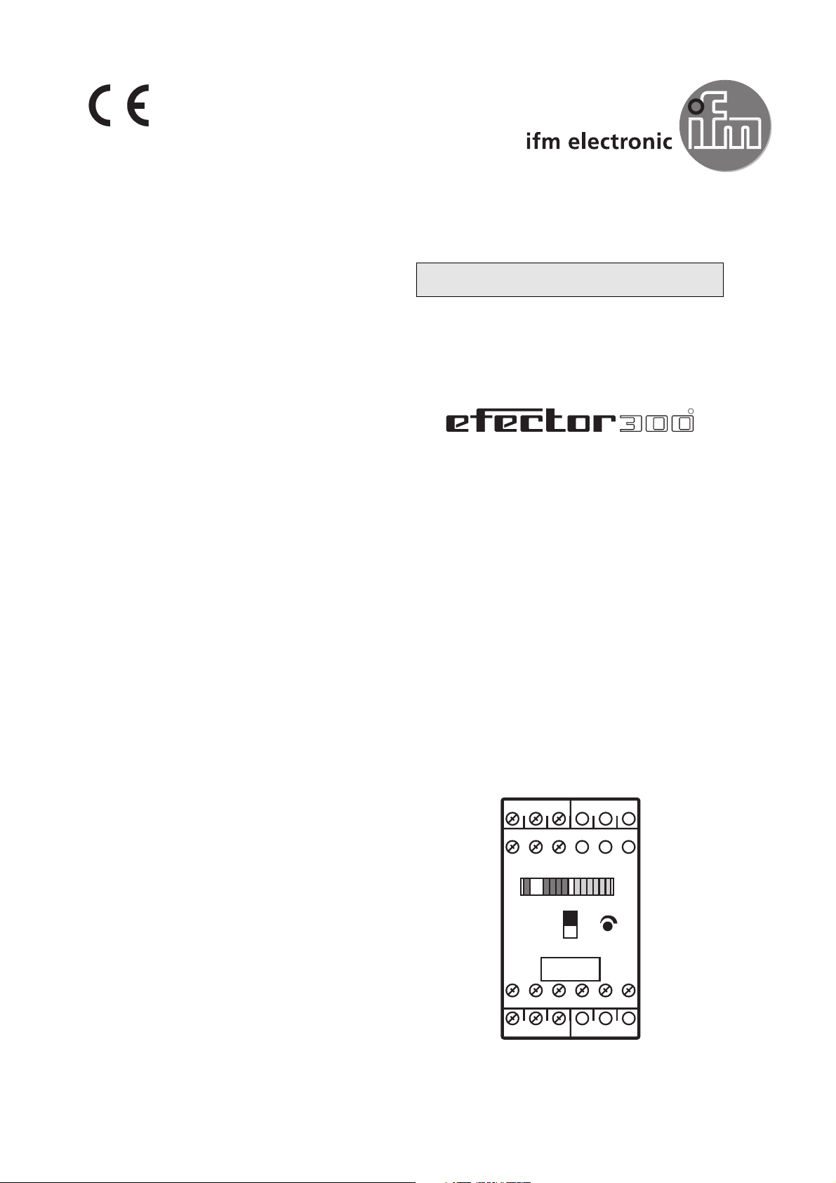
Control monitor
VS2000 Exi
PTB 01 ATEX 2075
7390212/01 07/03
ENGLISH
ifm electronic Ltd. • Hampton, Middlesex TW12 2HD • Tel. 0208 / 213-0000
R
1
78
13 14 15 16 17 18
19 20 21
3
2
9
+
-
Page 2

The operating instructions
... apply to all control monitors of type VS2000 Exi. The only difference between the
individual units is the height of the permissible AC or AC/DC power supply which is
indicated on the type label of the unit.
... are part of the unit. They contain information about the correct handling of the
product. Read them before use to familiarise yourself with operating conditions,
mounting and operation. Follow the safety instructions.
Contents
1. Safety instructions . . . . . . . . . . . . . . . . . . . . . . . . . . . . . . . . . page 2
2. Function and features . . . . . . . . . . . . . . . . . . . . . . . . . . . . . . page 3
3. Installation . . . . . . . . . . . . . . . . . . . . . . . . . . . . . . . . . . . . . . page 3
4. Electrical connection . . . . . . . . . . . . . . . . . . . . . . . . . . . . . . . page 4
5. Adjustment . . . . . . . . . . . . . . . . . . . . . . . . . . . . . . . . . . . . . . page 6
6. Function diagram flow monitoring . . . . . . . . . . . . . . . . . . . . . page 6
7. Installation and set-up / operation . . . . . . . . . . . . . . . . . . . . . page 7
8. Maintenance, repair, disposal . . . . . . . . . . . . . . . . . . . . . . . . . page 7
9. Technical data . . . . . . . . . . . . . . . . . . . . . . . . . . . . . . . . . . . . page 7
1. Safety instructions
T
he unit must be installed, connected and put into operation by a qualified
electrician as during the installation dangerous contact voltage occurs
and the safe function of the unit and the plant is only guaranteed when
installation is correctly carried out.
B
e careful when handling the connected unit. Due to the protection rating
IP 20 this is only allowed by qualified staff.
T
he design of the unit corresponds to the protection class II except for the
terminal blocks where protection against accidental contact (safety from
finger-touch to IP20) for operation by qualified staff is only guaranteed if the
terminal screw has been completely screwed in. This is why the unit always
has to be mounted in a control cabinet of at least IP 54 which can only be
opened by means of keys.
I
n case of malfunction of the unit or uncertainties please contact the manu-
facturer. Tampering with the device can seriously affect the safety of people and equipment. This is not permitted and leads to an exclusion of liability and warranty.
Page 2
Page 3
2. Function and features
The VS2000 Exi control monitor is designed to work with flow sensors of intrinsi-
cally safe design Ex"i". It meets the requirements according to EN50014 and
EN50020 (intrinsic safety "i").
The explosion group indicated on the unit as well as special conditions have to be
taken into account according to EC type test certificate PTB 01 ATEX 2075.
Marking:
• The unit provides intrinsically safe voltage supply for the sensors, evaluates the
signals from the sensors and signals whether a preset flow value has been
reached:
• Flows of either liquids or gases can be monitored.
• In addition the VS2000 Exi monitors the sensor cable: In the case of wire break
and short circuit the monitoring relay deenergises, the red LED is on.
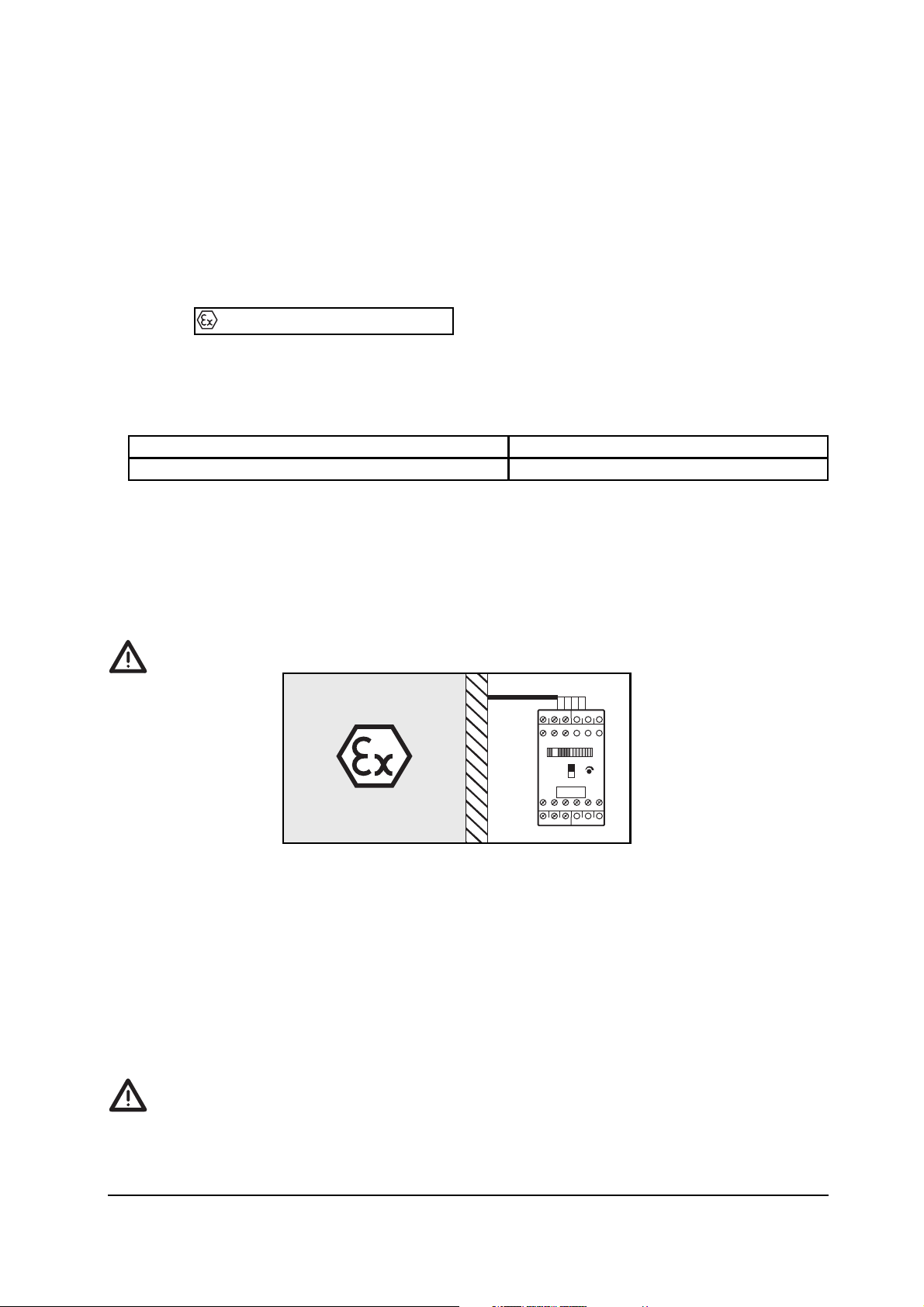
3. Installation
The VS2000 Exi must be mounted outside the Ex zone.
• Mount the unit in a control cabinet with a protection rating of at least IP 54 to
guarantee protection against accidental contact with dangerous contact voltages
and against atmospheric influence.
• The control cabinet should be installed in accordance with local and national rules
and regulations.
• Mount the unit on a DIN rail.
• Mount the unit vertically and leave enough space between the unit and the top
and bottom of the control cabinet to enable air circulation to avoid excessive heating.
When several units are mounted side by side the internal heating of all
units has to be considered. The ambient temperature for the individual unit
must not exceed the permissible value of +60°C.
Page 3
flow above the preset value output relay is energised
flow below the preset value output relay is deenergised
II (1) G [EEx ia] IIC
1
2
3
9
78
-
13 14 15 16 17 18
19 20 21
+
Page 4

In this case adhere to the distances between the units.
The following applies to identical VS2000 Exi units:
• Distance = 0 mm when operated with U
NOM
(see Technical data / Operating volt-
age).
• Distance = at least 10 mm when operated with U
NOM
+10%.
For units from other companies the permissible distance is to be determined by
measurements.
• Prevent the penetration of conductive or other dirt during installation and wiring.
Mounting of the sensors:
Adhere to the mounting instructions enclosed to the sensor.
4. Electrical connection
The unit must only be connected by a qualified electrician.
Isolate from mains supply before wiring!
Check if the relays are connected to voltages of external power supplies.
The rules and regulations for the installation and operation of electrical equipment
in hazardous areas must be observed.
Terminal connection:
Voltage supply
AC voltage:
According to Technical data (see page 13) / Type label ± 10% at the terminals 18 (L1)
and 17 (N), frequency range 47...63Hz.
DC voltage:
24V DC ± 10 %, at the terminals 18 (+) and 17 (-).
Page 4
Core colours:
BN = brown, BU = blue, BK = black,
WH = white, GY = grey
R1 = relay flow monitoring
R2 = relay wire monitoring
1/BN
4/BK
5/GY
2/WH
3/BU
1
2
3
7
8
9
15
13
14
16
17
18
21
19
20
R1
AC
N
L1
R2
DC
L-
L+
Page 5

Connection of sensors
Max. permissible values of the control circuits
for SN2301 ... SN2304:
Max. permissible values of the control circuits
for SR2301:
To prevent negative effects on the functions caused by noise voltages, sensor cables
and load cables should be laid separately. Maximum length of the sensor cable:
100m. Adhere to the maximum permissible values for the external inductance and
capacitance.
Output relay
Flow monitoring: terminals 13, 14, 15.
Wire monitoring: terminals 19, 20, 21.
Switching capacity: max. 250V AC, 4A (see Technical data, page 13).
The current must be externally limited to these values by taking appropriate measures.
External interference suppression of inductive loads is required.
Page 5
in the protection rating intrinsic safety
Voltage
[EEx ia] IIC and [EEx ia] IIB
Current
I
o
= 92mA / Ie= 47.2mA
U
o
= 15.8V
Power
P
o
= 680 mW
in the protection rating intrinsic safety
External inductance
[EEx ia] IIC [EEx ia] IIB [EEx ia] IIB
External capacitance 185nF
1mH
1.6µF
1mH
885nF
5mH
in the protection rating intrinsic safety
Voltage
[EEx ia] IIC and [EEx ia] IIB
Current
I
o
= 84mA / Ie= 38.5mA
U
o
= 15.8V
Power
P
o
= 680 mW
in the protection rating intrinsic safety
External inductance
[EEx ia] IIC [EEx ia] IIB [EEx ia] IIB
External capacitance 205nF
1mH
1.7µF
1mH
935nF
5mH
Page 6

5. Adjustment
1. Set the selector switch (3) to liquid or gaseous media:
= liquid, = gas.
2. Apply the operating voltage. After the power-on delay time (approx. 30 s) has
elapsed the unit is ready for operation; (during this time flow may be indicated).
3. Set the preset flow and keep it constant. Turn the setting potentiometer (4) until
a green LED lights. The farther the green LED lit is away from the yellow LED, the
safer is the adjustment (excess gain for flow or temperature fluctuations).
6. Function diagram flow monitoring
Page 6
Row of LEDs
- red LED is lit: flow below the switch point
- yellow LED is lit: relay is energised,
flow has reached the switch point
- green LED is lit: flow above the switch point
Selector switch medium (liquid/gas)
LED red
- is lit in case of wire break or short circuit
Setting potentiometer for switch point
1
3
2
4
preset flow
switch point
output relay
t1 = power-on delay time
1
2
78
3
9
1
2
3
+
-
4
13 14 15 16 17 18
19 20 21
f
t1
1
0
t
Page 7

7. Installation and set-up / operation
After mounting, wiring and setting check the safe functioning of the unit
In the case of wire break or short circuit of the sensor cable the relay "wire monitoring" is de-energised and the red LED lights. After rectification of the fault the control monitor is again ready for operation
8. Maintenance, repair, disposal
If used correctly no maintenance and repair measures are required.
Only the manufacturer is allowed to repair the unit.
After use dispose of the unit in an environmentally friendly way in accordance
with the applicable national regulations.
9. Technical data
Page 7
SN2302 SN2303 SN2304 SR2301SN2301
AC DC
230V 110V 200V 240V 24V
± 10%
5VA 125mA
-20 ... +60°C
IP 20
IP 40
plastic (noryl)
15 terminals max. 2 x 2.5mm
2
relay
max. 4A (250V AC, cos ϕ ≥ 0.7); 0.2 A (250V DC); 4A (24V DC)
Electrical design
Operating voltage
Voltage tolerance
Power/current consumption
Operating temperature
Protection terminals
Protection housing
Housing
Connection
Output
Contact rating
 Loading...