

Page 1

Operating instructions
Vibration sensor
VNB211
UK
80270676/00 12/2017
Page 2

Content
1 Preliminary note ��������������������������������������������������������������������������������������������������� 4
1�1 Notes on this document ��������������������������������������������������������������������������������� 4
1�2 Symbols used ������������������������������������������������������������������������������������������������4
2 Safety instructions �����������������������������������������������������������������������������������������������4
2�1 General ���������������������������������������������������������������������������������������������������������� 4
2�2 Installation and connection ����������������������������������������������������������������������������4
2�3 Tampering with the device �����������������������������������������������������������������������������5
3 Functions and features ����������������������������������������������������������������������������������������5
4 Installation������������������������������������������������������������������������������������������������������������6
5 Electrical connection �������������������������������������������������������������������������������������������� 7
5�1 M8/USB interface ������������������������������������������������������������������������������������������7
5�2 History values ������������������������������������������������������������������������������������������������7
5�3 Real-time clock ����������������������������������������������������������������������������������������������8
6 Functions �������������������������������������������������������������������������������������������������������������8
6�1 Monitoring function ����������������������������������������������������������������������������������������8
6�2 Input function �������������������������������������������������������������������������������������������������8
6�3 Output function (switching output and analogue output) �������������������������������9
6�4 Self-test����������������������������������������������������������������������������������������������������������9
6�5 Averaging of a vibration characteristic value �������������������������������������������������9
6�5�1 Calculation �������������������������������������������������������������������������������������������� 9
6�5�2 Settings �����������������������������������������������������������������������������������������������10
6�5�3 Diagram averaging �����������������������������������������������������������������������������10
6�6 Measuring function ��������������������������������������������������������������������������������������10
7 Operating and display elements ������������������������������������������������������������������������ 11
7�1 LED display ������������������������������������������������������������������������������������������������� 11
7�2 7-segment display ���������������������������������������������������������������������������������������12
7�3 Operating mode ������������������������������������������������������������������������������������������� 12
7�3�1 Examples in the operating mode ��������������������������������������������������������12
7�4 Operating mode external process value ������������������������������������������������������ 13
7�4�1 Example display change (v
- external process value) ��������������������13
rms
8 Device configuration ������������������������������������������������������������������������������������������14
8�1 Programming via pushbuttons ��������������������������������������������������������������������� 14
8�1�1 Global VNB parameters ����������������������������������������������������������������������14
2
Page 3

8�1�2 Characteristic vibration value �������������������������������������������������������������14
8�1�3 External process value �����������������������������������������������������������������������14
9 Menu ������������������������������������������������������������������������������������������������������������������ 14
9�1 Menu structure ��������������������������������������������������������������������������������������������� 15
9�2 Main menu ��������������������������������������������������������������������������������������������������� 15
9�2�1 V1 menu ���������������������������������������������������������������������������������������������16
9�2�2 V2 menu ���������������������������������������������������������������������������������������������16
9�2�3 EV1 menu ������������������������������������������������������������������������������������������� 16
9�2�4 EV2 menu ������������������������������������������������������������������������������������������� 17
9�2�5 EP1 menu ������������������������������������������������������������������������������������������� 17
9�2�6 EP2 menu ������������������������������������������������������������������������������������������� 18
9�2�7 Ext menu ��������������������������������������������������������������������������������������������18
9�2�8 Out menu �������������������������������������������������������������������������������������������� 19
9�3 Explanation of the menu ������������������������������������������������������������������������������ 20
UK
10 Parameter setting via the pushbuttons on the unit ������������������������������������������22
10�1 Parameter setting in general ���������������������������������������������������������������������22
10�1�1 Change from menu level 1 to the sub-menu ������������������������������������23
10�1�2 Locking / unlocking ���������������������������������������������������������������������������24
11 Maintenance, repair and disposal �������������������������������������������������������������������� 24
12 Scale drawing ��������������������������������������������������������������������������������������������������24
13 Time diagrams �������������������������������������������������������������������������������������������������25
13�1 Averaging for a characteristic vibration value ��������������������������������������������25
13�2 Switching delay for the upper limit monitor ������������������������������������������������ 26
13�3 Switching delay for the lower limit monitor ������������������������������������������������28
14 Factory setting �������������������������������������������������������������������������������������������������29
3
Page 4

1 Preliminary note
Technical data, approvals, accessories and further information at www�ifm�com�
1.1 Notes on this document
This document applies to devices of the type "vibration sensor" (art� no�: VNB211)�
It is part of the device and contains information about the correct handling of the
product�
This document is intended for qualified electricians� These specialists are people
who are qualified by their training and their experience to see and to avoid
possible hazards that may be caused during operation of the device�
► Read this document before using the device�
► Keep this document during the service life of the device�
1.2 Symbols used
► Instructions
> Reaction, result
→ Cross-reference
LED on
LED flashes
Important note
Non-compliance may result in malfunction or interference�
Information
Supplementary note
2 Safety instructions
2.1 General
► Observe these operating instructions�
► Observe the warning notes in these instructions�
Non-observance of the instructions, operation which is not in accordance with use
as prescribed below, wrong installation or incorrect handling can affect the safety
of operators and machinery�
2.2 Installation and connection
The device must only be installed, connected and put into operation by a qualified
electrician as the safe function of the device and machinery is only guaranteed
4
Page 5

when installation is correctly carried out� The installation and connection must
comply with the applicable national and international standards� Responsibility lies
with the person installing the device�
This is a class A product which is intended for use in industrial applications�
The unit may cause radio interference in domestic areas� In this case it can
be necessary for the user to take appropriate measures�
2.3 Tampering with the device
Tampering with the device is not allowed and will lead to an exclusion of liability
and warranty� Tampering with the device can affect the safety of operators and
UK
machinery�
3 Functions and features
The parameters of the device are mainly set via the VES004 PC software�
The device manual can be found at www�ifm�com
Monitoring of
• 2 sensor-internal characteristic vibration values (a/v, RMS/peak)
• 2 external characteristic vibration values (a/v, RMS/peak via VNA001
accelerometer) or two external process values (current value above and/or
below limit value)
Visualisation of
• Measured values
• Switching states
• Measured data via PC software
5
Page 6
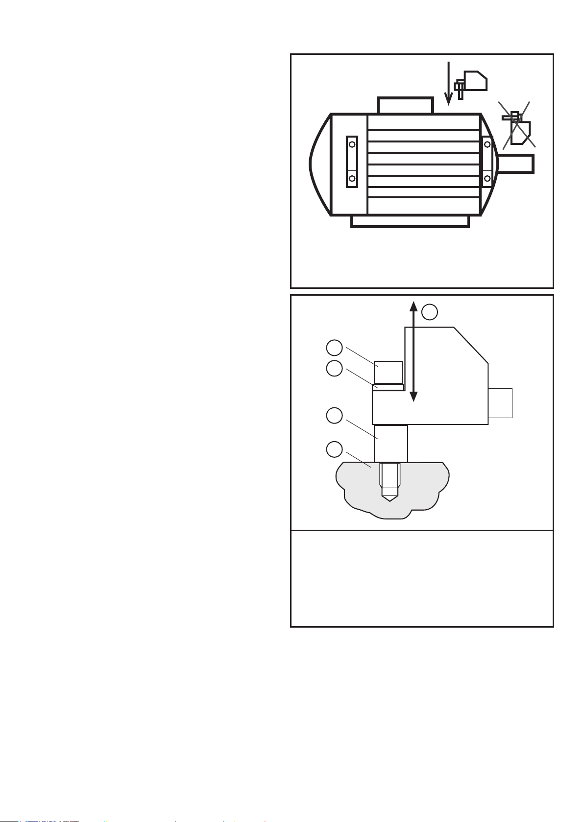
4 Installation
Please note the following points
when installing the unit:
► Mount only in a thick housing wall
(e�g� crane hook thread)�
► Mount vertically to the machine
surface using the spacer adapter
in the direction of the strongest
vibrations� This is usually the
radial direction�
► Tighten the M5 screw with a
tightening torque of 7 Nm�
► Ensure a reliable vibration
transmission� Avoid any elastic
intermediate layers�
1
2
3
4
5
1: Measurement axis
2: M5 screw
3: Spring washer
6
4: M8 x M5 adapter
5: Machine surface
Page 7
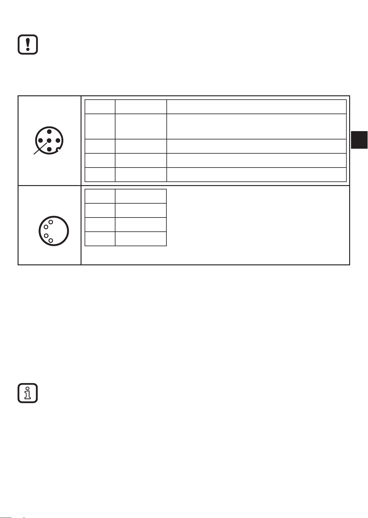
5 Electrical connection
The unit must be connected by a qualified electrician�
The national and international regulations for the installation of electrical equipment
must be adhered to�
Voltage supply to EN 50178, SELV, PELV�
Disconnect power before connecting the unit�
M12
M8
Pin 1: L+ 9�6���30 V DC
Pin 2: Out 1 Switching output or current output
Pin 3: L Pin 4: Out 2 Switching output
Pin 5: IN Current input 0/4���20 mA
Pin 1: VCC (5 V)
Pin 2: USB DPin 3: LPin 4: USB D+
5.1 M8/USB interface
0/4���20/22 mA (configurable)
UK
► First connect the interface cable to the device and then to the USB interface of
the computer�
• Communication with the PC software for parameter setting of the objects to be
monitored, to read and reset the history data and to visualise measured data�
• The devices have a serial number that can be read via the PC software�
• The sensor can also be supplied via the USB interface�
Switching and analogue outputs are not supported if a USB power supply is used�
5.2 History values
The unit has an internal history memory� The memory interval can be configured
for each object via the PC software (min� 1 s)� The maximum value and optionally
the average value in this interval are stored together with the time stamp in the
memory�
7
Page 8

The memory's capacity is 685,000 values; beyond this the oldest values are
overwritten (ring memory, FIFO)�
The history can be configured, read and reset via the PC software�
5.3 Real-time clock
The unit has an integrated real-time clock including a buffer battery for the time
stamp in the history memory� The time is synchronised with the system clock when
the history is reset via the PC software�
6 Functions
The basic functions of the unit are set via the PC software�
Only parameters for alarming and scaling of the signals can be set via the buttons
on the unit → 8.1 Programming via pushbuttons
6.1 Monitoring function
The VNB211 can monitor up to two internal characteristic vibration values� The
characteristic values are activated and configured via the PC software� Monitoring
can be effected in acceleration or vibration velocity in a frequency range that can
be set�
On delivery, the first characteristic value monitors the effective value of the
vibration velocity to ISO 10816 in the frequency range of 10���1000 Hz�
On delivery, the second characteristic value monitors the maximum peak of the
acceleration in the frequency range of 10���6000 Hz�
6.2 Input function
Monitoring can be extended by another vibration measuring point or a process
value via the external input of the VNB211�
For the external input it is also possible to monitor up to two characteristic
values� With an extension by a vibration measurement point (with a VNA001
accelerometer + Y cable) the same parameters can be configured as with internal
characteristic vibration values�With an extension by a process value (via an
analogue 4���20 mA current signal) the process value (e�g� a storage temperature
or pressure) can be monitored for exceeding and/or falling below the limit value�
On delivery, the first characteristic value for the external input is configured as
temperature monitoring (e�g� connection of a TT3237)�
The second characteristic value is deactivated on delivery�
8
Page 9

6.3 Output function (switching output and analogue output)
The two outputs of the VNB211 are used for the alarm (pre-alarm, main alarm)�
The first output (OU1) can be used as digital or analogue output� The switching
logic (which characteristic values are alarmed in which way) can be set only in the
PC software�
System errors (e�g� a failed self-test) are also signalled on the first output (OU1)�
If the output is used as digital output, the output pulses with a frequency of 1 Hz
in case of a fault� A current of 22 mA is provided as analogue output in case of a
system error�
UK
6.4 Self-test
The self-test checks the function of the VNB's measuring cell� The self-test
is made during power-on and can in addition be started manually via the PC
software or the buttons on the unit�
Displays on the unit:
• Self-test passed → [PASS]
• Self-test failed → [FAIL]
> LED OU1 flashes
Output OU1
- pulsing if "digital" output function (NC, NO)
- supplies 22 mA if "analogue" output function
6.5 Averaging of a vibration characteristic value
6.5.1 Calculation
Formula to determine the new diagnostic value:
("previous diagnostic value" x (1 - averaging)) + ("new measurement" x averaging)
= new diagnostic value
Example
Averaging 0�25; "previous diagnostic value" 17�3 mm/s;
"new measurement" 14�7 mm/s
(17�3 mm/s x (1 - 0�25)) + (14�7 mm/s x 0�25) = 16�65 mm/s
For the VNB211 the measurement time between "previous diagnostic value" and
"new measurement” can be configured via the PC software�
9
Page 10
6.5.2 Settings
1
1
0
10
15
20
25
30
35
5
4710 13 16 19 22 25 28 31 34 37 40 43 46 49 52 55 58 61 64 67 70 73 76 79 82 85 88 91 94 97
2
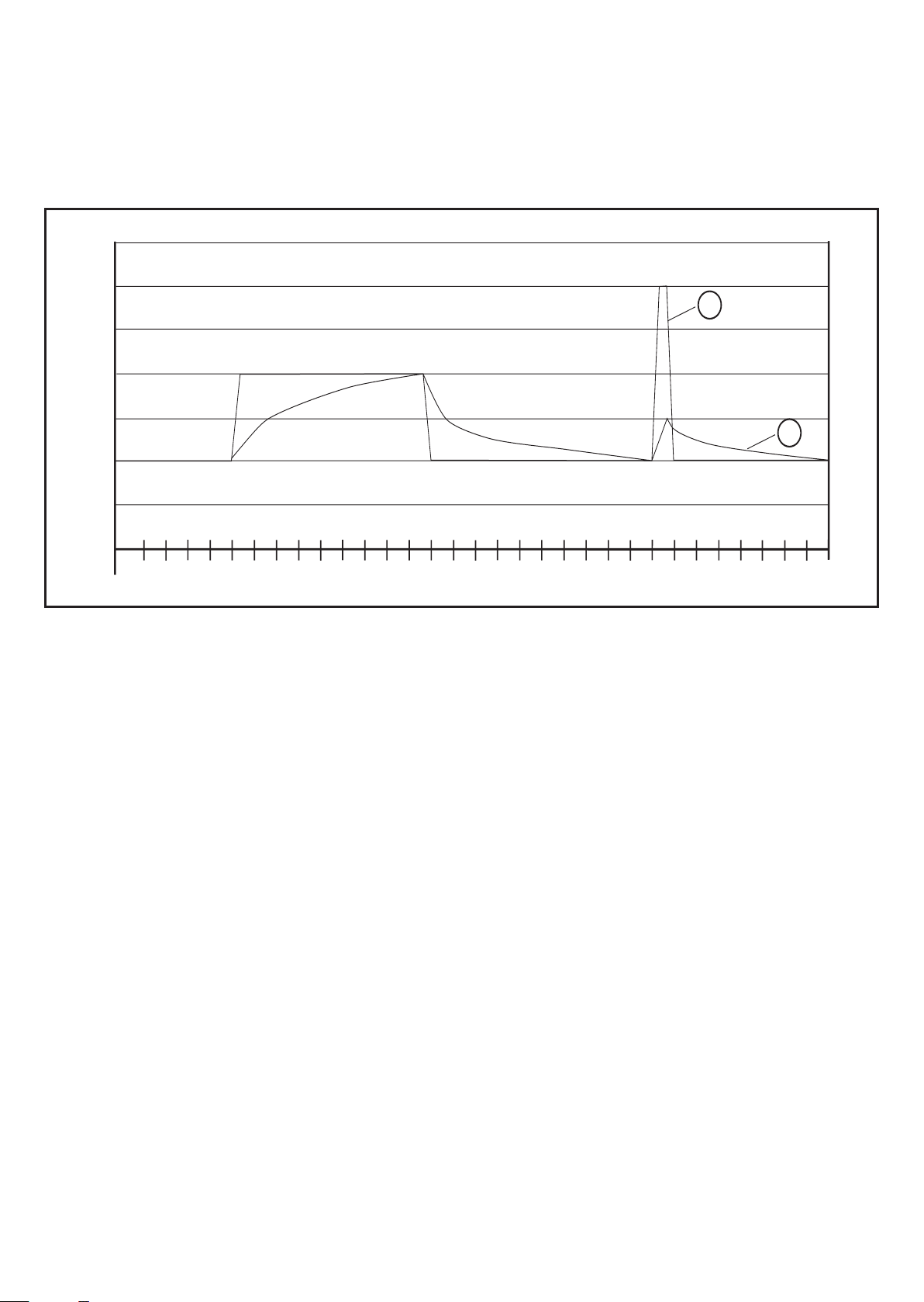
Averaging = 1: averaging deactivated
Averaging 0�01; strong averaging
6.5.3 Diagram averaging
1: Measured value
2: Averaged diagnostic value (averaging = 0�125)
6.6 Measuring function
The device can be set to the measurement mode via the VES004 software� In this
mode, you have access to the raw data (time signal) of the acceleration or of the
external input (4���20 mA)� The data can be visualised, recorded, analysed and
processed in the software�
If the device remains connected to the software, the user has to actively (manual
ly) finish the time signal monitoring� If the device is separated from the software, it
automatically returns to the monitoring function�
If the unit is in the measurement mode, there is no monitoring� "rSc3" is displayed
-
on the unit�
10
Page 11

7 Operating and display elements
7.1 LED display
10
Mode/Enter Set
11
12
1...8: LED display
UK
1: LED green a = vibration velocity a [g] or [m/s²]
2: LED green v = vibration velocity v [mm/s] or [in/s]
3: LED green d = not used
4: LED green RMS = average value
5: LED green Pk = peak value
6: LED green Ext = process value of the external transducer
7: LED yellow OU1 = pre-alarm active *)
8: LED red OU2 = main alarm active *)
*) The LED indicates the current alarm state (warning alarm, damage alarm)� The configu
ration of the corresponding output (OU1, OU2) as "normally closed" or "normally open" is
ignored�
9: 7-segment display green, yellow and red, 4 digits
- Display of the measured values
10: Points
- Lower points as decimal separators
-
11: Set button
Parameter setting mode
- Setting of the parameter values
- Change of display between the configured characteristic values
12: Mode/Enter button
- Selection of the parameters and acknowledgement of the parameter values�
11
Page 12

7.2 7-segment display
• Displays the damage level (green, yellow, red)
If the segment display changes the colour, the switch-on and switch-off delays or
the hysteresis are not considered�
• Display of the current measured value for the selected object
• Display of the configuration menu and its parameters
7.3 Operating mode
The user must know the objects configured in the vibration sensor and in the external
sensor� The display allows no indication of the unit if the external input is used for
process value monitoring�
7.3.1 Examples in the operating mode
Colour segment display: yellow
a
v
d
RMSPk
Ext
OU1
OU2
Colour segment display: red
a
v
d
RMSPk
Ext
OU1
OU2
Current measured value of the 1st object,
e�g� vibration velocity v
= 17�35 mm/s�
rms
Parameters
- Pre-alarm SP1 = 10 mm/s
- Main alarm SP2 = 20 mm/s
> Output OU1 is active
Current measured value of the 2nd object,
e�g� imbalance (v
) = 1�252 in/s
peak
Parameters
- Unit uni = in/s
- Early warning SP1 = 0�5 in/s
- Main alarm SP2 = 1 in/s
12
> Outputs OU1 and OU2 are active
Page 13

Colour segment display: red
2
a
v
d
RMSPk
Ext
OU1
OU2
Current measured value external analogue sensor,
temperature ϑ = 95 °C
Parameters
- Pre-alarm ESP1 = 50 °C
- Main alarm ESP2 = 90 °C
> Outputs OU1 and OU2 are active
The LEDs OU1 and OU2 indicate the alarm condition, not the voltage level (high,
UK
low) at the output�
The level can be inverted via the parameters OU1 and OU2 (NC, NO)�
7.4 Operating mode external process value
In the operating mode "external process value" measured values are displayed,
e�g� temperatures, pressure values or other characteristic vibration values�
The detected values are transferred via the measured value input (pin 5)�
> LED "Ext" lights�
7.4.1 Example display change (v
a
v
d
RMSPk
Ext
OU1OU
Configuration
1 characteristic vibration value + 1 external process
value
- external process value)
rms
Normal operating mode
Set
Vibration velocity 17�35 mm/s v
rms
[Set]
Operating mode external process value
e.g. temperature 42.61 °C
a
v
d
RMS
Pk
Ext
OU1
OU2
[Set]
Normal operating mode
Vibration velocity 17�35 mm/s v
rms
13
Page 14

8 Device configuration
8.1 Programming via pushbuttons
The following settings can be made via the pushbuttons on the unit�
8.1.1 Global VNB parameters
- Scaling of the input (4���20 mA, for use for the external process value)
- Scaling of the output (4���20 mA, if OU1 = analogue)
- Switching function of the outputs (NC, NO)
- Switch-on and switch-off delays
- Self-test
- Unit (mm/s, inch/s)
8.1.2 Characteristic vibration value
- Averaging
- Switchpoints (pre-alarm and main alarm)
8.1.3 External process value
- Switch points
- Hysteresis
All other settings of the sensor are made via the PC software� There it is defined
how many and which characteristic values (characteristic vibration values and/or
process values) are to be monitored → device manual.
9 Menu
Depending on the configuration of the sensor the menu level 1 is adapted via
the PC software� There are only menu items whose characteristic values were
configured via the PC software�
If the external input in the PC software is configured for an analogue current
signal, the menu items EV1) and EV2) are not available�
If the external input in the PC software is configured for an accelerometer
(VNA001), the menu items EP1) and EP2) are not available�
14
Page 15

9.1 Menu structure
9.2 Main menu
Vibration
Ext. input
Main
menu
UK
15
Page 16

9.2.1 V1 menu
9.2.2 V2 menu
9.2.3 EV1 menu
The menu for the external characteristic vibration value 1 is only available if it was
configured in the PC software�
16
Page 17

9.2.4 EV2 menu
The menu for the external characteristic vibration value 2 is only available if it was
configured in the PC software�
UK
9.2.5 EP1 menu
17
Page 18

9.2.6 EP2 menu
The menu for the external process value 2 is only available if it was configured in
the PC software�
9.2.7 Ext menu
18
Page 19

9.2.8 Out menu
UK
19
Page 20

9.3 Explanation of the menu
Menu level 1
V1 ) Sub-menu for the characteristic vibration value 1
V2 ) Sub-menu for the characteristic vibration value 2
EV1) Sub-menu for the external characteristic vibration value 1 with respective
configuration
EV2) Sub-menu for the external characteristic vibration value 2 with respective
configuration
EP1) Sub-menu for the external process value 1
EP2) Sub-menu for the external process value 2 with respective configuration
EXT) Sub-menu for the external input
in the configuration as analogue input
OUT) Sub-menu for the outputs
Uni Unit of the vibration velocity - mm/s or in/s
Test Self-test - (PASS or FAIL)
is automatically made when the sensor is switched on
Sub-menu characteristic vibration values V1) and V2)
The values indicated for the switch points SP1 and SP2 of characteristic values of the
vibration velocity change when another unit is selected�
SP1 Switch point pre-alarm
If the switch point is exceeded,
- OU1 switches, if it is digital
- the yellow LED "OU1" lights
- the measured value display changes to yellow
SP2 Switch point main alarm
If the switch point is exceeded,
- OU2 switches
- the red LED "OU2" lights
- the measured value display changes to red
AUER Averaging → chapter 6.5
20
Page 21

Sub-menu external characteristic vibration values EV1) and EV2) with respective
configuration
ESP1 Switch point pre-alarm
If the switch point is exceeded,
- OU1 switches, if it is digital
- the yellow LED "OU1" lights
- the measured value display changes to yellow
ESP2 Switch point main alarm
If the switch point is exceeded,
- OU2 switches
- the red LED "OU2" lights
- the measured value display changes to red
AUER Averaging → chapter 6.5
Sub-menu external characteristic vibration values EP1) and EP2) with respective
configuration
ESP1 Switch point pre-alarm
If the switch point is exceeded,
- OU1 switches, if it is digital
- the yellow LED "OU1" lights
- the measured value display changes to yellow
Eh1 Hysteresis pre-alarm
Absolute distance between set and reset point
ESP2 Switch point main alarm
UK
If the switch point is exceeded,
- OU2 switches
- the red LED "OU2" lights
- the measured value display changes to red
Eh2 Hysteresis main alarm
Absolute distance between set and reset point
Sub-menu external input as analogue current input
EASP Scaling of external sensor for the process value,
initial value of the measuring range at 4 mA
EAEP Scaling of external sensor for the process value,
final value of the measuring range at 20 mA
Sub-menu outputs
ou1 Switching logic OU1 (OU1 = digital)
NC, NO (normally closed, normally open)
21
Page 22

ASP1 Scaling current output with respective configuration
(OU1 = analogue), value at 4 mA
AEP1 Scaling current output with respective configuration
(OU1 = analogue), value at 20 mA
ou2 Switching logic OU2
NO, NC (normally open, normally closed)
dS1 Switch-on delay for OU1 (0���60 s)
dr1 Switch-off delay for OU1 (0���60 s)
dS2 Switch-on delay for OU2 (0���60 s)
dr2 Switch-off delay for OU2 (0���60 s)
Error message
Err1 The value to be displayed is less than -999 or greater than 9999�
► Check the scaling of the current output (ASP1, AEP1) and set again�
10 Parameter setting via the pushbuttons on the unit
During the parameter setting process the monitoring function of the unit is
maintained� It continues to monitor with the existing parameters until the parameter
setting has been completed�
10.1 Parameter setting in general
3 steps must be taken for each parameter setting:
Select parameter
1
► Press [Mode/Enter] until the reque-
sted parameter is displayed.
Mode/Enter Set
22
Page 23

Set parameter value
Mode/Enter Set
2
► Press [Set].
> The current setting value of the
parameter is displayed�
► Press [Set] for 3 s.
► Setting of the decimal point (cc�
cc) and the sign by pressing [Set]
several times�
► Press [Mode/Enter] to confirm.
► Set an individual digit with [Set] and
confirm with [Mode/Enter].
► Repeat with all digits�
Acknowledge parameter value
3
► Press [Mode/Enter].
> The parameter is displayed again�
Mode/Enter Set
The new setting value is saved�
Set other parameters
► Start again with step 1�
Change the operating mode
► Press [Mode/Enter] several times until the current measured value is displayed.
> The unit returns to the operating mode�
If no button is pressed within 30 s, the unit automatically returns to the operating mode�
UK
10.1.1 Change from menu level 1 to the sub-menu
► Press [Mode/Enter] until [EF
displayed�
► Briefly press [Set].
> The first parameter of the submenu is
displayed (here: [LFCO]).
┘
] is
Mode/Enter Set
Mode/Enter Set
23
Page 24

10.1.2 Locking / unlocking
The unit can be locked electronically to prevent unintentional settings�
► Make sure that the unit is in the
normal operating mode�
► Press [Mode/Enter] + [Set] for 10 s.
> [Loc] is displayed.
During operation: [Loc] is briefly displayed if you try to change parameter values.
For unlocking:
► Press [Mode/Enter] + [Set] for 10 s.
> [uLoc] is displayed.
On delivery: not locked�
Mode/Enter Set
Mode/Enter Set
11 Maintenance, repair and disposal
► Dispose of the device in accordance with the national environmental
regulations�
12 Scale drawing
62,4
51
36
14
5,3
6
M12x1
20
M5
24
37,6
10
4
M8x1
5,3
5
Page 25

13 Time diagrams
13.1 Averaging for a characteristic vibration value
The time diagram shows the effect of averaging for a characteristic vibration value�
The outputs are configured as normally open (OU1 and OU2 → NO), averaging
(AUER) = 0�25�
rms [mm/s]
v
1
SP1
SP2
24 V
0 V
OU 2 (n.o.)
ds2, dr2 = 0 s
off
OU 1 (n.o.)
10
10
on
off
on
20
20
2
UK
t [s]
t [s]
24 V
ds1, dr1 = 0 s
0 V
1: Raw signal
2: Averaged signal
off
on
10
off
on
20
t [s]
25
Page 26

13.2 Switching delay for the upper limit monitor
The time diagram shows the effect of the switching delay on the analogue input
for an upper limit monitor (ESP1 < ESP2)� The outputs are set as normally closed
(OU1 and OU2 → NC).
Analogue In
[°C]
Eh2
Eh1
ESP2
{
ESP1
{
24 V
0 V
24 V
10
OU 1 (n.c.)
ds1, ds2, dr1, dr2 = 0 s
on
10
OU 2 (n.c.)
20
20
off
off
t [s]
off
on
t [s]
off
0 V
24 V
0 V
24 V
0 V
on
10
OU 1 (n.c.)
ds1, ds2 = 2 s / dr1, dr2 = 3 s
2 s
10
OU 2 (n.c.)
ds1, ds2 = 2 s / dr1, dr2 = 3 s
2 s
3 s
on
10
on
20
20
20
on
t [s]
off
3 s
1
t [s]
off
2
t [s]
1: Not switched off because the selected switching delay is too short (< 3 s)�
2: Not switched on because the selected switching delay is too short (< 2 s)�
26
Page 27

If the switching delays of pre-alarm and main alarm are set differently:
- main alarm already switched on, pre-alarm not yet switched on
- pre-alarm already switched off, main alarm not yet switched off
UK
27
Page 28

13.3 Switching delay for the lower limit monitor
The time diagram shows the effect of the switching delay on the analogue input for
a lower limit monitor (ESP1 > ESP2)� The outputs are set as normally closed (OU1
and OU2 → NC).
Analogue In
[°C]
{
Eh1
ESP1
Eh2{
24 V
0 V
ESP2
24 V
0 V
24 V
0 V
24 V
0 V
10
OU 1 (n.c.)
ds1, ds2, dr1, dr2 = 0 s
on
10
OU 2 (n.c.)
off
on
10
OU 1 (n.c.)
ds1, ds2 = 2 s / dr1, dr2 = 3 s
2 s
on
10
OU 2 (n.c.)
ds1, ds2 = 2 s / dr1, dr2 = 3 s
2 s
on
10
off
3 s
3 s
off
off
on
on
2 s
20
20
off
20
20
20
t [s]
off
t [s]
t [s]
off
3 s
t [s]
1
t [s]
1: Not switched on because the selected switching delay is too short�
28
Page 29

14 Factory setting
Factory setting User setting
Global settings
Input filter 10 Hz high pass
Characteristic vibration
value 1
Filter 1000 Hz low pass
Evaluation method RMS
Degree of integration Vibration velocity
Measurement time 0�25 s
History interval 300 s
History values Maximum value + average
value
Characteristic vibration
value 2
Filter 6000 Hz low pass
Evaluation method Peak
Degree of integration Acceleration
Measurement time 0�25 s
UK
History interval 300 s
History values Maximum value + average
value
External input
Usage Analogue signal
Scaling VNA (if used =
VNA)
Input filter (if used = VNA) Not used
External process value 1
Measurement time 0�5 s
Not used
29
Page 30

Factory setting User setting
History interval 300 s
History values Maximum value + average
value
External process value 2 Not used
Measurement time
History interval
History values
External
characteristic vibration
value 1
Filter
Evaluation method
Degree of integration
Measurement time
History interval
History values
External
characteristic vibration
value 2
Not used
Not used
Filter
Evaluation method
Degree of integration
Measurement time
History interval
History values
Outputs
30
Page 31

Factory setting User setting
Switching logic pre-alarm Characteristic vibration value
1 or characteristic vibration
value 2 or external process
value
Switching logic main alarm Characteristic vibration value
1 or characteristic vibration
value 2 or external process
value
UK
The following list indicates the factory settings of the parameters that can be set
via the pushbuttons on the unit:
Factory setting User setting
Characteristic vibration
value 1
SP1 (pre-alarm) 2.8 [mm/s]
SP2 (main alarm) 4.5 [mm/s]
rms
rms
AUER (averaging) 0�125
Characteristic vibration
value 2
SP1 (pre-alarm) 5 [g]
SP2 (main alarm) 7.5 [g]
peak
peak
AUER (averaging) 1
External
Not used
characteristic vibration
value 1
ESP1 (pre-alarm)
ESP2 (main alarm)
AUER (averaging)
External
characteristic vibration
value 2
Not used
31
Page 32

Factory setting User setting
ESP1 (pre-alarm)
ESP2 (main alarm)
AUER (averaging)
External process value 1
ESP1 (pre-alarm) 10
ESP2 (main alarm) 20
Eh1 (hysteresis pre-alarm) 1
Eh2
(Hysteresis main alarm)
External process value 2 Not used
1
ESP1 (pre-alarm)
ESP2 (main alarm)
Eh1 (hysteresis pre-alarm)
Eh2
(Hysteresis main alarm)
External input
EASP (4 mA) 0
EAEP (20 mA) 100
Outputs
ou1 (output 1) NC (normally closed)
ASP1
(4 mA, if ou1 = I)
Not used
AEP1
(20 mA, if ou1 = I)
ou2 (output 2) NC (normally closed)
dS1 switch-on delay prealarm
dr1 switch-off delay prealarm
Not used
0 [s]
0 [s]
32
Page 33

Factory setting User setting
dS2 switch-on delay main
alarm
dr2 switch-off delay main
alarm
Display
uni Metric
0 [s]
0 [s]
UK
33
 Loading...