

Page 1
Operating instructions
Ultrasonic diffuse-reflection sensor
with IO-Link
UGT203
UGT206
UGT509
UGT512
80275568 / 00 05 / 2018
UK
Page 2
2
1 Safety instructions
• Read this document before setting up the product and keep it during the entire
service life.
• The product must be suitable for the corresponding applications and
environmental conditions without any restrictions.
• Only use the product for its intended purpose (→ 2 Functions and features).
• If the operating instructions or the technical data are not adhered to, personal
injury and/or damage to property may occur.
• The manufacturer assumes no liability or warranty for any consequences
caused by tampering with the product or incorrect use by the operator.
• Installation, electrical connection, set-up, operation and maintenance of the
product must be carried out by qualified personnel authorised by the machine
operator.
• Protect units and cables against damage.
2 Functions and features
Ultrasonic sensor for monitoring levels and detecting objects.
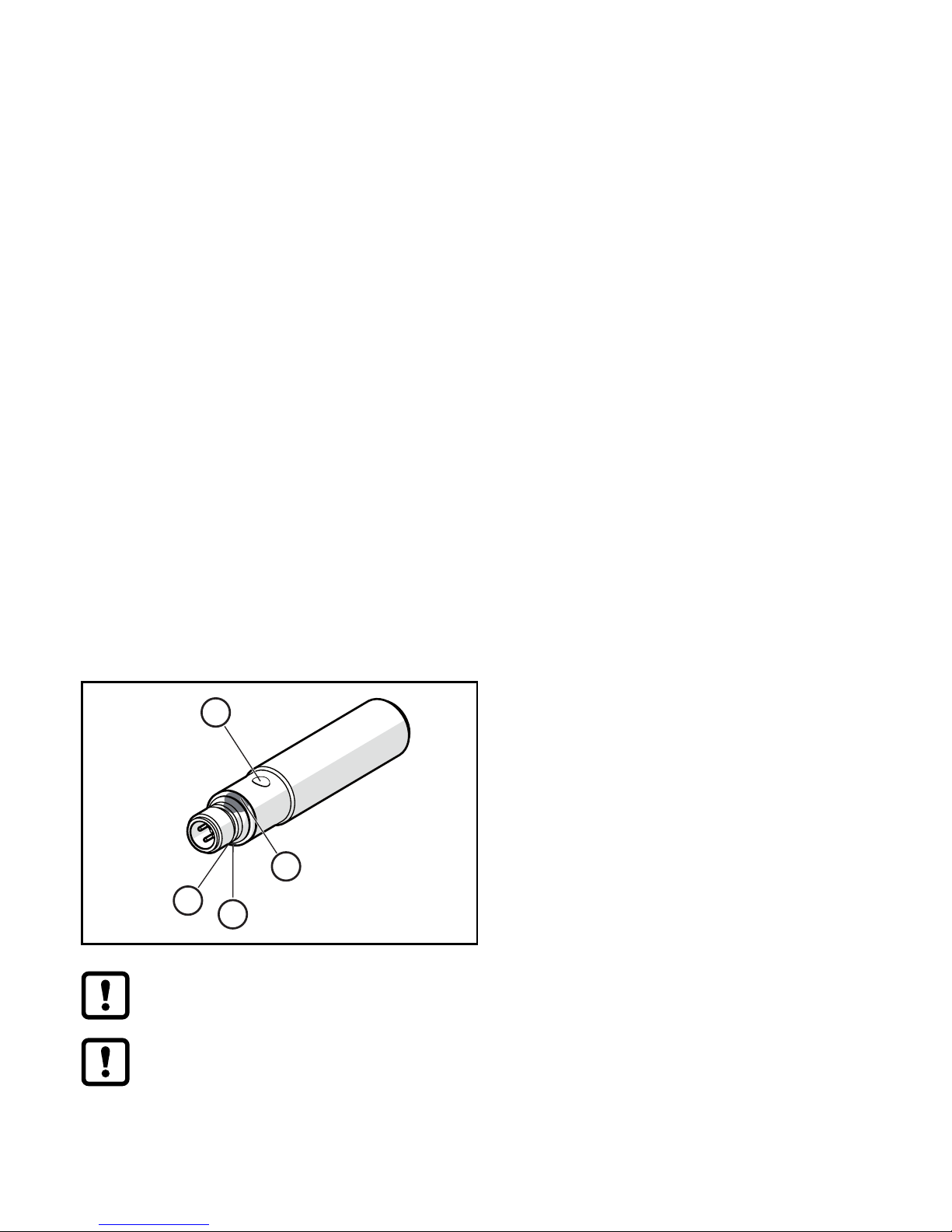
3 Installation
3
4
1
2
► Secure the unit to a bracket.
1/2: status LEDs 1/2 (yellow),
setting aid and output indication
3: echo LED (green), is on when object or
background is detected
4: teach button
Sound-absorbing surfaces have a negative effect on a reliable function.
► Consider the dead zone (→ Technical data sheet):
No object detection in the dead zone.
Page 3

3
UK
For units with metal housing (according to UL 508):
► Keep a distance of at least 12.7 mm between the sensor and non-
insulated metal material.
For further information please refer to www.ifm.com
→ General information about installation and operation.
4 Electrical connection
► Disconnect power.
► Connect unit (depending on the type selected):
BK: black
BN: brown
BU: blue
WH: white
BN
WH
BK
BU
4
1
3
2
OUT2
L
+
L
OUT1
• OUT1: switching output / IO-Link
• OUT2: switching output
colours to DIN EN 60947-5-2
5 Settings
The unit and the parameters are set via the IO-Link interface (→ 5.1) or the
teach button (→ 5.2).
5.1 IO-Link
This unit has an IO-Link communication interface which enables direct access to
process and diagnostic data. In addition it is possible to set the parameters of the
unit while it is in operation. Operation of the unit via an IO-Link interface requires
an IO-Link master.
With a PC, suitable IO-Link software and an IO-Link adapter cable communication
is possible when the system is not in operation.
The IODDs necessary for the configuration of the unit, detailed information about
process data structure, diagnostic information, parameter addresses and the
necessary information about the required IO-Link hardware and software can be
found at www.ifm.com.
Page 4

4
5.2 Teach button
5.2.1 Start programming mode
► Press the teach button for 2 s...6 s.
> Yellow status LEDs 1/2 flash (1 Hz), the unit is in the programming mode.
If programming has not been completed successfully, the unit returns to the
previous setting.
5.2.2 Set output response
► Start programming mode (→ 5.2.1).
► Position the object in P1 (Fig. 1 or 2).
► Press the teach button for 1 s.
> Yellow status LEDs 1/2 flash (2.5 Hz), P1 setting is completed.
► Position the object in P2 (Fig. 1 or 2).
► Press the teach button for 1 s.
> Yellow status LEDs 1/2 flash briefly (4 Hz), P2 setting is completed.
5.2.3 Invert output response
► Press the teach button for > 6 s.
> Yellow status LEDs 1/2 flash (> 10 Hz).
> Yellow status LEDs 1/2 flash briefly (> 4 Hz).
> Output function is inverted.
5.2.4 Restore factory setting
► Align the unit so that no echo is received.
> Green echo LED off.
► Start programming mode (→ 5.2.1).
► Press the teach button for 1 s.
> Yellow status LEDs 1/2 flash briefly (4 Hz), factory setting is restored.
Page 5

5
UK
In case of object recognition, the following output signals are provided:
Fig. 1: Window function P1 > P2
Fig. 2: Hysteresis function P1 = P2
B P2 P1
T
B P1/P2
T
Switching outputs Complementary switching outputs
1
1
B P2 P1
1
0
0
3
4
2
B P1/P2
2
1
0
1
0
1
3
4
Inverted switching outputs Inverted switching outputs
1
1
B P2 P1
1
0
0
2
3
4
1
1
B P1/P2
1
0
0
2
3
4
1: output response
2: distance to the object
3: OUT1 (switching output)
4: OUT2 (switching output)
B: blind zone
P: taught position
T: teach button
Technical data and further information at www.ifm.com
 Loading...