

Page 1
Operating instructions
Ultrasonic diffuse reflective sensors
UG-
UGA
UGQ
80237716 / 00 04 / 2016
UK
Page 2
2
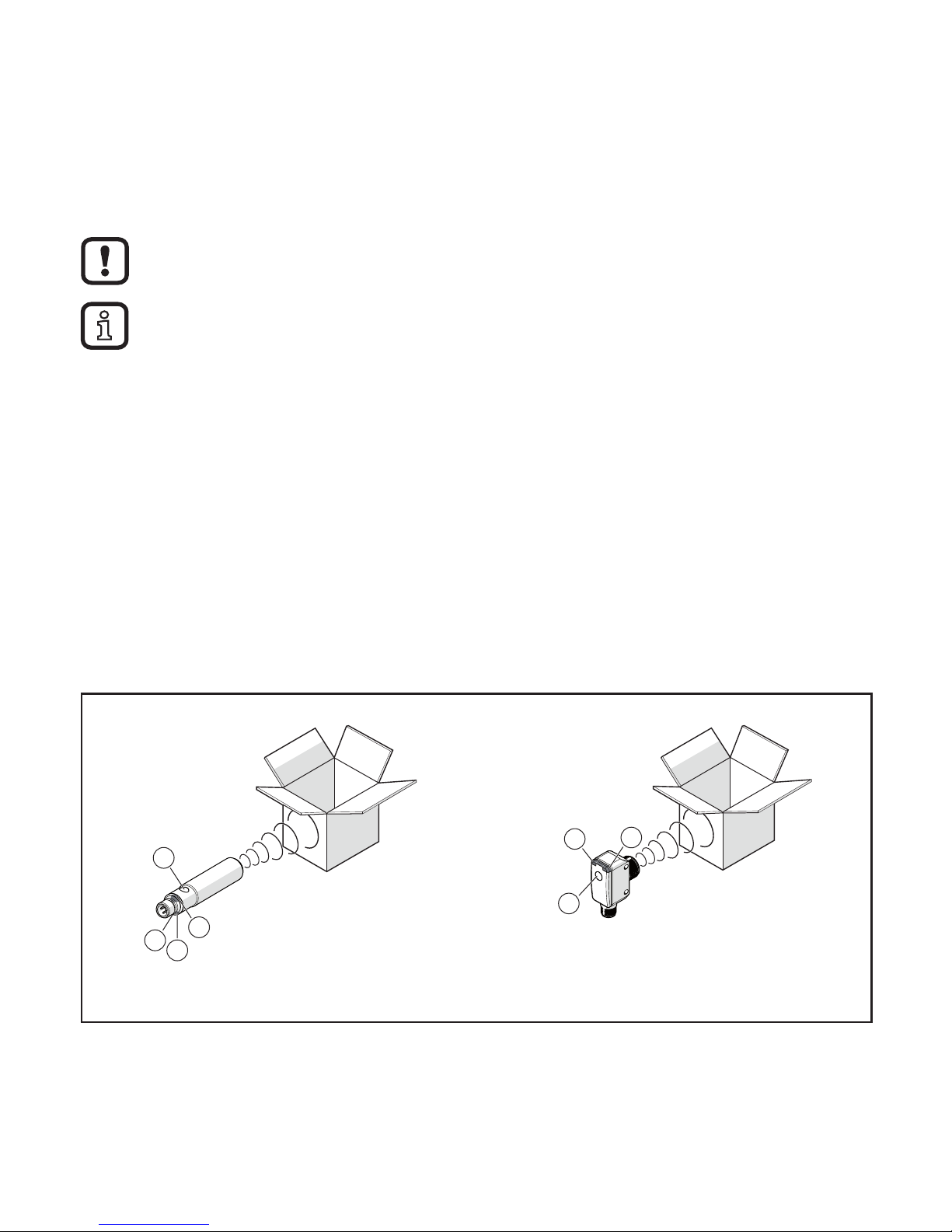
1 Preliminary note
1.1 Symbols used
► Instructions
> Reaction, result
→ Cross-reference
Important note
Non-compliance may result in malfunction or interference.
Information Supplementary note.
2 Safety instructions
• Installation, electrical connection, set-up, operation and maintenance of the unit
must be carried out by qualified personnel authorised by the machine operator.
3 Functions and features
Ultrasonic sensors detect objects of various materials without any contact.
Depending on the selected sensor, detected objects are signalled via switching
outputs or their distance is indicated by means of a proportional analogue signal.
4 Installation
UG-xxx / UGAxxx UGQxxx
3
4
2
1
3
1
4
1: Status LED P1 (yellow)
2: Status LED P2 (yellow)
3: Echo LED (green)
4: Set button
► Position object.
► Align the ultrasonic sensor so that it directly faces the object or the background
and secure it to a bracket.
> Object / background is detected when the echo LED (green) lights.
Page 3

3
UK
Sound-absorbing surfaces have a negative effect on a reliable function.
During installation of the device, consider the blind zone.
5 Electrical connection
► Disconnect power.
► Connect device (depending on the type selected):
Core colours
4
2 1
3
4
1
3
2
OUT2
L
+
L
OUT1
OUT1: Switching output
BK Black
OUT2: Switching /
analogue output
BN Brown
BU Blue
WH White
Colours to DIN EN 60947-5-2
Technical data and further information at → www.ifm.com
6 Set-up
Note the LED behaviour for the set-up:
Echo LED green
On Echo is received.
Off No echo (object / background not detected).
Off For the time of resetting to factory setting.
Status LEDs yellow
LED 1 LED 2 Function acknowledgement
Flashes 1 Hz x x Programming mode active.
Flashes 2.5 Hz x x Setting distance P1 completed.
Flashes 4 Hz x x Setting distance P2 completed or
assignment acknowledgement of the setting.
Flashes 10 Hz x x Inverting the switching characteristics.
Page 4

4
7 Settings
► Start programming mode of the device.
► Press button 2 s...6 s.
> LEDs flash (1 Hz).
If programming has not been completed successfully, the device returns to
the previous setting.
7.1 Window function, distance P1 > P2
► Object in position P1.
► Press button once 1 s.
> LEDs flash (2.5 Hz).
► Object in position P2.
► Press button once 1 s.
> LEDs flash (4 Hz).
B P2 P1
Output response of the switching outputs Output response of the switching /
analogue output
B P2 P1
Y
X
Y
X
1
2
B P2 P1
Y
X
Y
X
1
2
X: Distance B: Blind zone
Y: Output response P1: Setting point 1 (OUT1)
①:
OUT1 (switching output) P2: Setting point 2 (OUT2)
②:
OUT2 (switching output / analogue output)
Page 5

5
UK
7.2 Hysteresis function, distance P1 = P2
► Object in position P1.
► Press button once 1 s.
> LEDs flash (2.5 Hz).
► Object in position P2.
► Press button once 1 s.
> LEDs flash (4 Hz).
B P1/P2
Output response of the switching outputs:
complementary
Output response of the switching /
analogue output
B P1/P2
Y
X
Y
X
1
2
B P1/P2
Y
X
Y
X
1
2
7.3 Inverting the output response
► Press button > 6 s.
> LEDs flash (> 10 Hz).
> Output functions are inverted (NO becomes NC or vice versa).
7.4 Restore factory setting
► Align the device so that no echo is received.
► Go into the programming mode of the unit.
► Press button once for 1 s.
> LEDs flash shortly with 4 Hz.
8 Operation
► Check whether the unit operates correctly.
> Display by LEDs:
Green LED is lit. Echo is received.
Yellow LED P1 is lit. Output 1 is switched.
Yellow LED P2 is lit. Output 2 is switched.
Green LED flashes. Short circuit at the output.
The minimum distance between the “Proximity Switch Metal Enclosure“ and
any “External uninsulated live part“ shall be at least 12.7 mm.
 Loading...