

IFM Electronic TW2000, TW2001, TW2101, TW2011, TW2100 Operating Instructions Manual
...
Operating instructions
Infrared temperature sensor
TW20xx
TW21xx
80270318 / 00 10 / 2017
UK
°F °C

2
Contents
1 Preliminary note ��������������������������������������������������������������������������������������������������� 4
1�1 Key to the symbols ����������������������������������������������������������������������������������������4
2 Safety instructions �����������������������������������������������������������������������������������������������4
3 Functions and features ����������������������������������������������������������������������������������������4
4 Function ��������������������������������������������������������������������������������������������������������������� 5
4�1 Process measured signals ����������������������������������������������������������������������������5
4�2 Emissivity of the objects to be measured ������������������������������������������������������5
4�3 Switching function ������������������������������������������������������������������������������������������ 6
4�4 Analogue function ������������������������������������������������������������������������������������������7
4�5 Delay time for the switching output OUT1 �����������������������������������������������������8
4�6 Simulation function ����������������������������������������������������������������������������������������9
4�7 Test function ���������������������������������������������������������������������������������������������������9
4�8 Damping function ����������������������������������������������������������������������������������������� 10
4�9 Peak-hold function ��������������������������������������������������������������������������������������� 10
4�10 IO-Link �������������������������������������������������������������������������������������������������������10
5 Installation���������������������������������������������������������������������������������������������������������� 11
6 Electrical connection ������������������������������������������������������������������������������������������ 14
6�1 Screening and grounding ����������������������������������������������������������������������������15
7 Operating and display elements ������������������������������������������������������������������������15
8 Menu ������������������������������������������������������������������������������������������������������������������ 16
8�1 Menu structure ��������������������������������������������������������������������������������������������� 16
8�2 Explanation main menu �������������������������������������������������������������������������������16
8�3 Explanation extended functions (EF) �����������������������������������������������������������17
8�4 Submenu simulation (SIM) ��������������������������������������������������������������������������17
9 Set-up ����������������������������������������������������������������������������������������������������������������18
10 Parameter setting ��������������������������������������������������������������������������������������������18
10�1 Parameter setting in general ���������������������������������������������������������������������19
10�1�1 Switching between the menu levels �������������������������������������������������20
10�1�2 Locking / unlocking ���������������������������������������������������������������������������20
10�1�3 Timeout ��������������������������������������������������������������������������������������������� 20
10�2 Settings for temperature monitoring ����������������������������������������������������������21
10�2�1 Setting the degree of emissivity ��������������������������������������������������������21

3
UK
10�2�2 Emissivity for TW2000, TW2100 �����������������������������������������������������22
10�2�3 Emissivities for TW2001, TW2101, TW2011, TW2002 ��������������������� 23
10�2�4 Settings for limit value monitoring with OUT1 �����������������������������������24
10�2�5 Set the analogue signal for OUT2 ����������������������������������������������������24
10�3 User settings (optional) ������������������������������������������������������������������������������24
10�3�1 Set the standard unit of measurement for temperature �������������������� 24
10�3�2 Set delay time for OUT1 �������������������������������������������������������������������24
10�3�3 Set the measured value damping ����������������������������������������������������� 24
10�3�4 Set the peak-hold function ���������������������������������������������������������������� 24
10�3�5 Setting the simulation function ����������������������������������������������������������24
10�4 Service functions ���������������������������������������������������������������������������������������25
10�4�1 Reset all parameters to factory setting ���������������������������������������������25
11 Operation ���������������������������������������������������������������������������������������������������������25
11�1 Changing the display unit in the Run mode �����������������������������������������������25
11�2 Read the set parameters ���������������������������������������������������������������������������25
12 Technical data and scale drawing �������������������������������������������������������������������� 25
13 Troubleshooting �����������������������������������������������������������������������������������������������26
14 Maintenance, repair and disposal �������������������������������������������������������������������� 26
15 Factory setting �������������������������������������������������������������������������������������������������27

4
1 Preliminary note
Technical data, approvals, accessories and further information at
www�ifm�com�
1.1 Key to the symbols
► Instructions
> Reaction, result
[…] Designation of keys, buttons or indications
→ Cross-reference
Important note
Non-compliance may result in malfunction or interference�
Information
Supplementary note�
2 Safety instructions
• Read this document before setting up the product and keep it during the entire
service life�
• The product must be suitable for the corresponding applications and environmental conditions without any restrictions�
• Only use the product for its intended purpose (→ Functions and features).
• If the operating instructions or the technical data are not adhered to, personal
injury and/or damage to property may occur�
• The manufacturer assumes no liability or warranty for any consequences
caused by tampering with the product or incorrect use by the operator�
• Installation, electrical connection, set-up, operation and maintenance of the unit
must be carried out by qualified personnel authorised by the machine operator�
• Protect units and cables against damage�
3 Functions and features
The unit monitors the temperature of particularly hot objects or those with difficult
access�
It detects the infrared radiation of objects without contact and converts it into an
electrical signal and an analogue output signal (4���20 mA)�

5
UK
4 Function
4.1 Process measured signals
• The unit features an IO-Link interface
• The unit displays the measured temperature�
• It generates two output signals according to the parameter setting:
OUT1: switching output / IO-Link Parameter setting
- switching signal: limit values for temperature (→ 10.2.4)
OUT2: analogue output Parameter setting
- analogue signal for temperature (→ 10.2.5)
4.2 Emissivity of the objects to be measured
The infrared temperature sensor reacts to the heat or infrared radiation emitted
from the object� This depends on the material and the surface� To get exact measurement results, the emissivity of the object to be measured has to be set on the
unit (→ 10.2.1 Setting the degree of emissivity)�
The emissivity of an ideal heat radiator (black body) is 100%� The emissivity for
real bodies is below 100 %� The emissivities indicated in the tables (→ 10.2.2
and → 10.2.3) are approximate values� To determine the temperature precisely a
reference value measurement should be made�
The reference value for TW2000 / TW2100 up to a temperature of 250 °C
can be measured using the enclosed label
To compensate environmental influences it may be useful to set a higher
emissivity� Therefore a setting up to 110 % is possible�
An incorrectly set emissivity leads to faults during temperature
measurement�
6
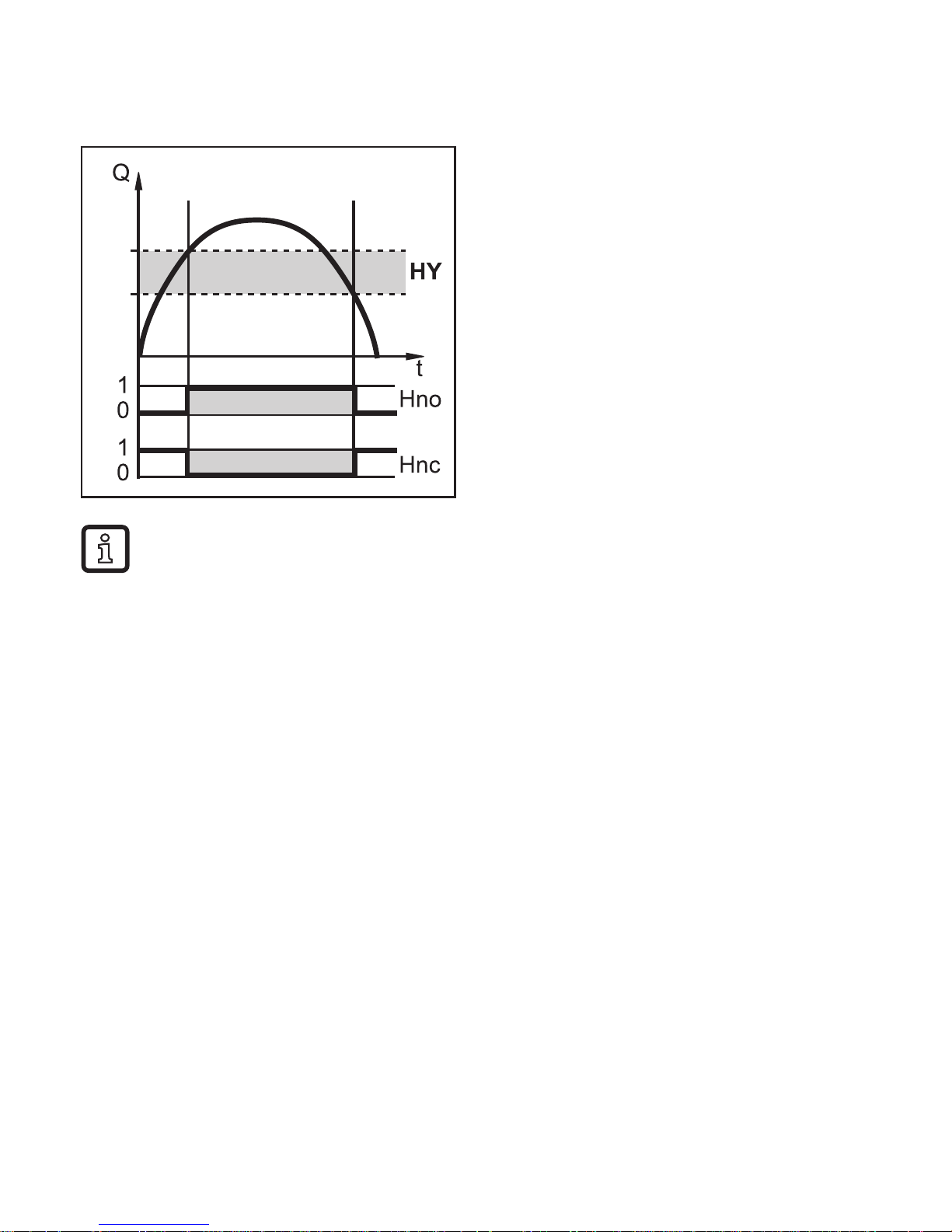
4.3 Switching function
OUT1 changes its switching state if it is above or below the set switching limits
(SP1, rP1)�
SP
rP
NO: [ou1] = [Hno]
NC: [ou1] = [Hnc]
First the set point (SP1) is set, then
the reset point (rP1) with the requested difference�
When SP1 is adjusted, rP1 is changed automatically; the difference remains the same�
Exception: SP1 is reduced to such an extent that if the distance is kept
constant, rP1 would fall below the measuring range� In such a case rP1 is
kept on the initial value of the measuring range�
7
UK
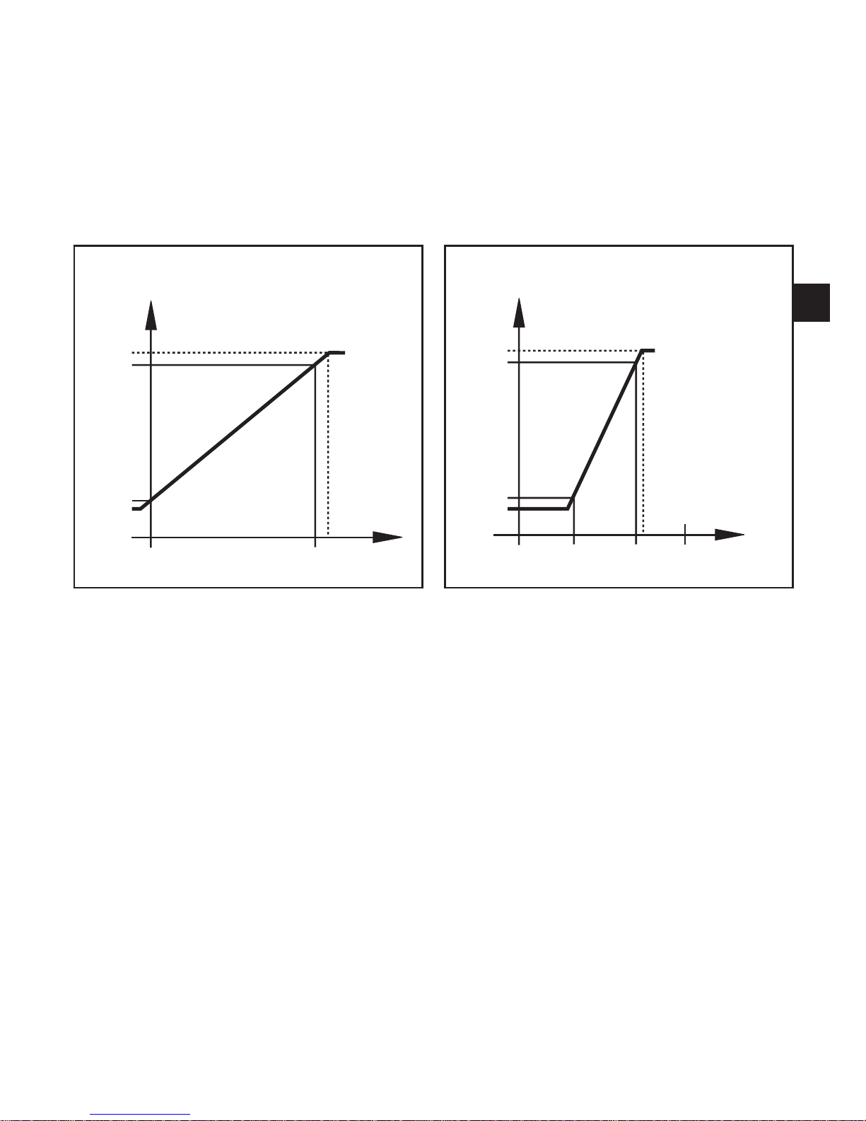
4.4 Analogue function
The unit converts the measured signal into a temperature-proportional analogue
signal ranging from 4���20 mA�
The measuring range is scalable:
• [ASP2] determines at which measured value the output signal is 4 mA�
• [AEP2] determines at which measured value the output signal is 20mA�
Measuring range in case of factory setting Measuring range in case of scaling
MAW MEW
20.5
20
4
3.8
T [°C/°F]
I [mA]
I [mA]
T [°C/°F]MEWMAW AEP2ASP2
20.5
20
4
3.8
MAW = Initial value of the measuring range
MEW = Final value of the measuring range
ASP2 = Analogue start point
AEP2 = Analogue end point
8
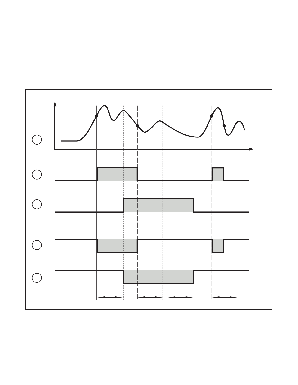
4.5 Delay time for the switching output OUT1
When a delay time is set (→ 10.3.2), OUT1 does not change its switching state
right away when the set switching limits (SP1, rP1) are exceeded or not reached
but only after the delay time (power-on delay time dS1, power-off delay time
dr1) has elapsed� If the switching condition is no longer met after the delay has
elapsed, the switching state of the output does not change�
Switching function on OUT1 with and without delay time:
dS1 dS1dr1dr1
t
T
1
0
1
0
1
0
1
0
SP
rP
1
2
3
4
5
T = temperature
SP = set point
rP = reset point
t = time
dS1 = switch-on delay time
dr1 = switch-off delay time

9
UK
(1) Temperature curve of the medium
(2) Hno (hysteresis function / normally open)
(3) Hno with switch-on and switch-o delay
(4) Hnc (hysteresis function, normally closed)
(5) Hnc with power-on and power-o delay
4.6 Simulation function
The simulation function is helpful when setting up the installation�
Via the SIM menu (→ 10.3.5), it is possible to activate a simulation of any
measured temperature within the measuring range� The simulation influences the
display and the outputs� After an adjustable period of time, the simulation function
stops automatically� To indicate that the simulation mode is activated, the display
alternates between the simulated measured value and "SIM"�
4.7 Test function
The infrared temperature sensor has an internal test function to check the complete signal processing, the switching output and the analogue output�
The test function is activated by a static signal on pin 5 or via IO-Link� The test
function simulates a radiation detector signal which generates an output current
of 20�5 mA and triggers the switching function when the sensor operates correctly
unless the switching output has already switched depending on the configuration�
[OL] is displayed�
The unit remains in the test mode as long as the static signal is on pin 5� If the test
function is started via IO-Link, the duration is 10 s� After that, the unit automatically
returns to the RUN mode�
To trigger the test function a static signal (10���34 V to IEC 61131-2) > 300 ms has
to be applied via pin 5� The test function is deactivated via a static "low" signal
> 300 ms on pin 5�
If the test function is not used:
► Put the test input (pin 5) to minus supply�
► Alternatively use a 4-pole socket in which pin 5 is not connected�
 Loading...