

Page 1
Operating instructions
Infrared temperature sensor
TW20xx
TW21xx
80270318 / 00 10 / 2017
UK
°F °C
Page 2

2
Contents
1 Preliminary note ��������������������������������������������������������������������������������������������������� 4
1�1 Key to the symbols ����������������������������������������������������������������������������������������4
2 Safety instructions �����������������������������������������������������������������������������������������������4
3 Functions and features ����������������������������������������������������������������������������������������4
4 Function ��������������������������������������������������������������������������������������������������������������� 5
4�1 Process measured signals ����������������������������������������������������������������������������5
4�2 Emissivity of the objects to be measured ������������������������������������������������������5
4�3 Switching function ������������������������������������������������������������������������������������������ 6
4�4 Analogue function ������������������������������������������������������������������������������������������7
4�5 Delay time for the switching output OUT1 �����������������������������������������������������8
4�6 Simulation function ����������������������������������������������������������������������������������������9
4�7 Test function ���������������������������������������������������������������������������������������������������9
4�8 Damping function ����������������������������������������������������������������������������������������� 10
4�9 Peak-hold function ��������������������������������������������������������������������������������������� 10
4�10 IO-Link �������������������������������������������������������������������������������������������������������10
5 Installation���������������������������������������������������������������������������������������������������������� 11
6 Electrical connection ������������������������������������������������������������������������������������������ 14
6�1 Screening and grounding ����������������������������������������������������������������������������15
7 Operating and display elements ������������������������������������������������������������������������15
8 Menu ������������������������������������������������������������������������������������������������������������������ 16
8�1 Menu structure ��������������������������������������������������������������������������������������������� 16
8�2 Explanation main menu �������������������������������������������������������������������������������16
8�3 Explanation extended functions (EF) �����������������������������������������������������������17
8�4 Submenu simulation (SIM) ��������������������������������������������������������������������������17
9 Set-up ����������������������������������������������������������������������������������������������������������������18
10 Parameter setting ��������������������������������������������������������������������������������������������18
10�1 Parameter setting in general ���������������������������������������������������������������������19
10�1�1 Switching between the menu levels �������������������������������������������������20
10�1�2 Locking / unlocking ���������������������������������������������������������������������������20
10�1�3 Timeout ��������������������������������������������������������������������������������������������� 20
10�2 Settings for temperature monitoring ����������������������������������������������������������21
10�2�1 Setting the degree of emissivity ��������������������������������������������������������21
Page 3

3
UK
10�2�2 Emissivity for TW2000, TW2100 �����������������������������������������������������22
10�2�3 Emissivities for TW2001, TW2101, TW2011, TW2002 ��������������������� 23
10�2�4 Settings for limit value monitoring with OUT1 �����������������������������������24
10�2�5 Set the analogue signal for OUT2 ����������������������������������������������������24
10�3 User settings (optional) ������������������������������������������������������������������������������24
10�3�1 Set the standard unit of measurement for temperature �������������������� 24
10�3�2 Set delay time for OUT1 �������������������������������������������������������������������24
10�3�3 Set the measured value damping ����������������������������������������������������� 24
10�3�4 Set the peak-hold function ���������������������������������������������������������������� 24
10�3�5 Setting the simulation function ����������������������������������������������������������24
10�4 Service functions ���������������������������������������������������������������������������������������25
10�4�1 Reset all parameters to factory setting ���������������������������������������������25
11 Operation ���������������������������������������������������������������������������������������������������������25
11�1 Changing the display unit in the Run mode �����������������������������������������������25
11�2 Read the set parameters ���������������������������������������������������������������������������25
12 Technical data and scale drawing �������������������������������������������������������������������� 25
13 Troubleshooting �����������������������������������������������������������������������������������������������26
14 Maintenance, repair and disposal �������������������������������������������������������������������� 26
15 Factory setting �������������������������������������������������������������������������������������������������27
Page 4

4
1 Preliminary note
Technical data, approvals, accessories and further information at
www�ifm�com�
1.1 Key to the symbols
► Instructions
> Reaction, result
[…] Designation of keys, buttons or indications
→ Cross-reference
Important note
Non-compliance may result in malfunction or interference�
Information
Supplementary note�
2 Safety instructions
• Read this document before setting up the product and keep it during the entire
service life�
• The product must be suitable for the corresponding applications and environmental conditions without any restrictions�
• Only use the product for its intended purpose (→ Functions and features).
• If the operating instructions or the technical data are not adhered to, personal
injury and/or damage to property may occur�
• The manufacturer assumes no liability or warranty for any consequences
caused by tampering with the product or incorrect use by the operator�
• Installation, electrical connection, set-up, operation and maintenance of the unit
must be carried out by qualified personnel authorised by the machine operator�
• Protect units and cables against damage�
3 Functions and features
The unit monitors the temperature of particularly hot objects or those with difficult
access�
It detects the infrared radiation of objects without contact and converts it into an
electrical signal and an analogue output signal (4���20 mA)�
Page 5

5
UK
4 Function
4.1 Process measured signals
• The unit features an IO-Link interface
• The unit displays the measured temperature�
• It generates two output signals according to the parameter setting:
OUT1: switching output / IO-Link Parameter setting
- switching signal: limit values for temperature (→ 10.2.4)
OUT2: analogue output Parameter setting
- analogue signal for temperature (→ 10.2.5)
4.2 Emissivity of the objects to be measured
The infrared temperature sensor reacts to the heat or infrared radiation emitted
from the object� This depends on the material and the surface� To get exact measurement results, the emissivity of the object to be measured has to be set on the
unit (→ 10.2.1 Setting the degree of emissivity)�
The emissivity of an ideal heat radiator (black body) is 100%� The emissivity for
real bodies is below 100 %� The emissivities indicated in the tables (→ 10.2.2
and → 10.2.3) are approximate values� To determine the temperature precisely a
reference value measurement should be made�
The reference value for TW2000 / TW2100 up to a temperature of 250 °C
can be measured using the enclosed label
To compensate environmental influences it may be useful to set a higher
emissivity� Therefore a setting up to 110 % is possible�
An incorrectly set emissivity leads to faults during temperature
measurement�
Page 6
6
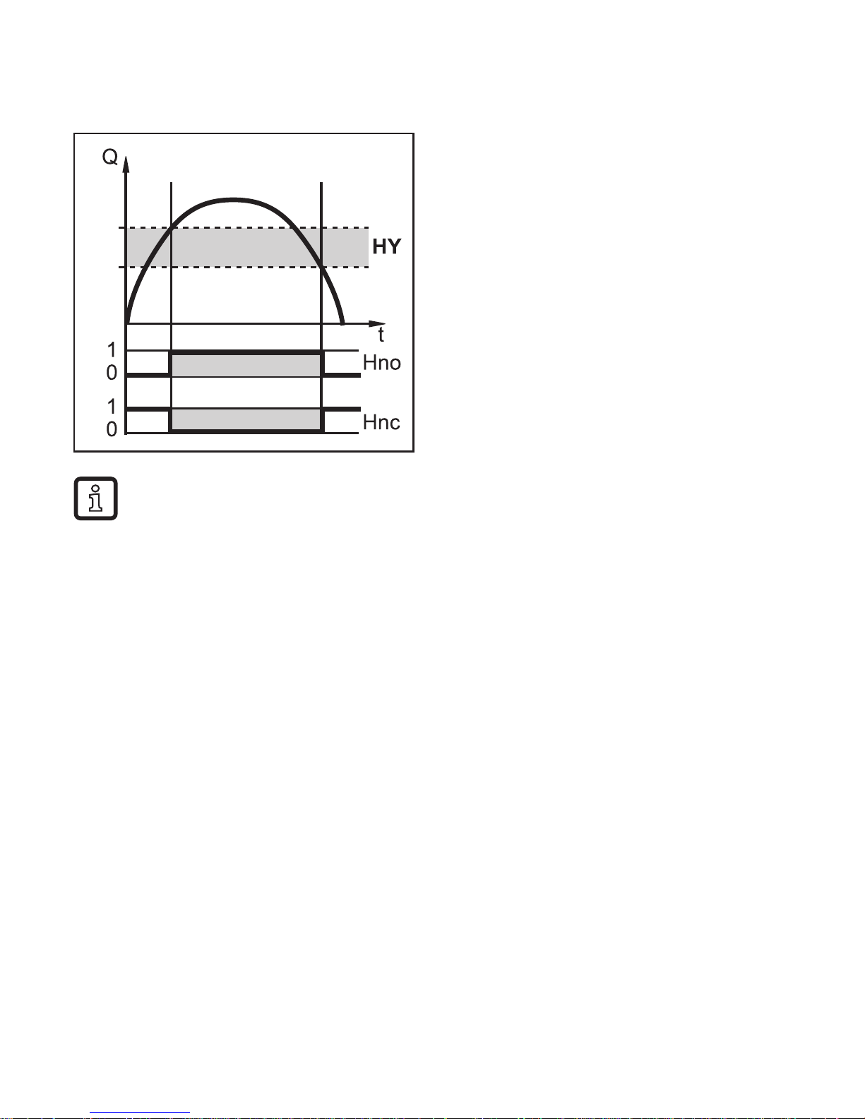
4.3 Switching function
OUT1 changes its switching state if it is above or below the set switching limits
(SP1, rP1)�
SP
rP
NO: [ou1] = [Hno]
NC: [ou1] = [Hnc]
First the set point (SP1) is set, then
the reset point (rP1) with the requested difference�
When SP1 is adjusted, rP1 is changed automatically; the difference remains the same�
Exception: SP1 is reduced to such an extent that if the distance is kept
constant, rP1 would fall below the measuring range� In such a case rP1 is
kept on the initial value of the measuring range�
Page 7
7
UK
4.4 Analogue function
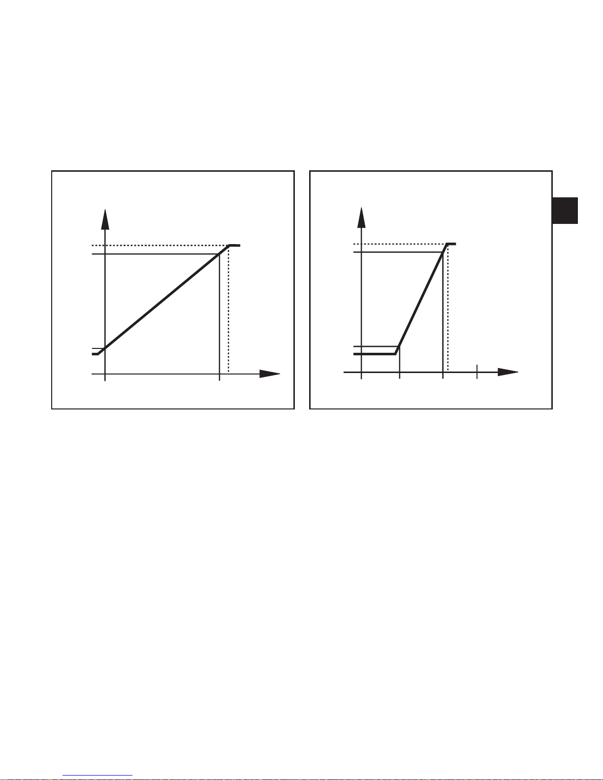
The unit converts the measured signal into a temperature-proportional analogue
signal ranging from 4���20 mA�
The measuring range is scalable:
• [ASP2] determines at which measured value the output signal is 4 mA�
• [AEP2] determines at which measured value the output signal is 20mA�
Measuring range in case of factory setting Measuring range in case of scaling
MAW MEW
20.5
20
4
3.8
T [°C/°F]
I [mA]
I [mA]
T [°C/°F]MEWMAW AEP2ASP2
20.5
20
4
3.8
MAW = Initial value of the measuring range
MEW = Final value of the measuring range
ASP2 = Analogue start point
AEP2 = Analogue end point
Page 8
8
4.5 Delay time for the switching output OUT1
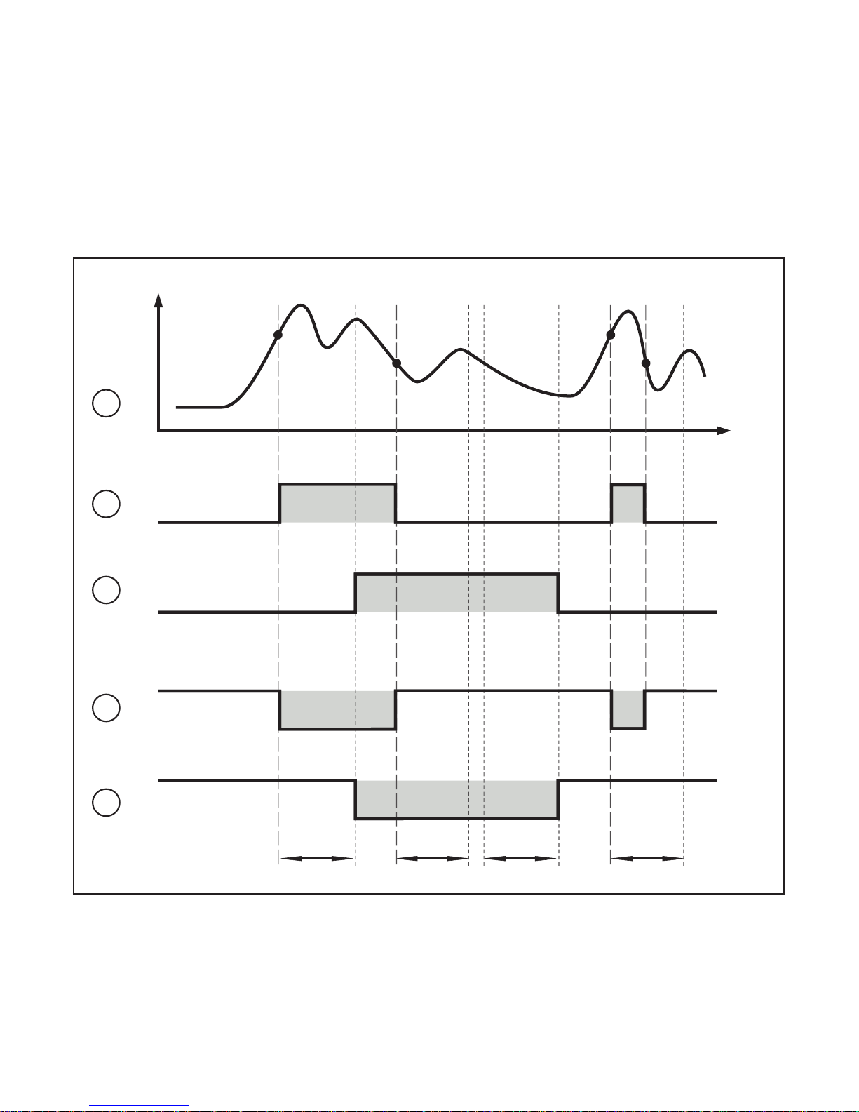
When a delay time is set (→ 10.3.2), OUT1 does not change its switching state
right away when the set switching limits (SP1, rP1) are exceeded or not reached
but only after the delay time (power-on delay time dS1, power-off delay time
dr1) has elapsed� If the switching condition is no longer met after the delay has
elapsed, the switching state of the output does not change�
Switching function on OUT1 with and without delay time:
dS1 dS1dr1dr1
t
T
1
0
1
0
1
0
1
0
SP
rP
1
2
3
4
5
T = temperature
SP = set point
rP = reset point
t = time
dS1 = switch-on delay time
dr1 = switch-off delay time
Page 9

9
UK
(1) Temperature curve of the medium
(2) Hno (hysteresis function / normally open)
(3) Hno with switch-on and switch-o delay
(4) Hnc (hysteresis function, normally closed)
(5) Hnc with power-on and power-o delay
4.6 Simulation function
The simulation function is helpful when setting up the installation�
Via the SIM menu (→ 10.3.5), it is possible to activate a simulation of any
measured temperature within the measuring range� The simulation influences the
display and the outputs� After an adjustable period of time, the simulation function
stops automatically� To indicate that the simulation mode is activated, the display
alternates between the simulated measured value and "SIM"�
4.7 Test function
The infrared temperature sensor has an internal test function to check the complete signal processing, the switching output and the analogue output�
The test function is activated by a static signal on pin 5 or via IO-Link� The test
function simulates a radiation detector signal which generates an output current
of 20�5 mA and triggers the switching function when the sensor operates correctly
unless the switching output has already switched depending on the configuration�
[OL] is displayed�
The unit remains in the test mode as long as the static signal is on pin 5� If the test
function is started via IO-Link, the duration is 10 s� After that, the unit automatically
returns to the RUN mode�
To trigger the test function a static signal (10���34 V to IEC 61131-2) > 300 ms has
to be applied via pin 5� The test function is deactivated via a static "low" signal
> 300 ms on pin 5�
If the test function is not used:
► Put the test input (pin 5) to minus supply�
► Alternatively use a 4-pole socket in which pin 5 is not connected�
Page 10
10
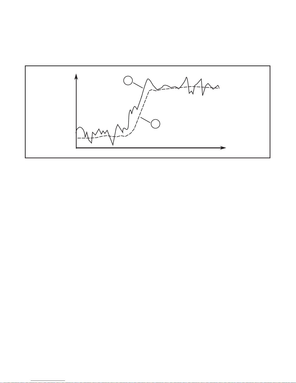
4.8 Damping function
If there are brief fluctuations in the temperature of the object to be measured, the
damping function stabilises the measured signal� The higher the selected time
constant dAP (→ 10.3.3 Set the measured value damping) the lower the influence
of the interfering temperature fluctuations on the measured value�
OUT2
[mA]
2
1
t
(1) Output signal without smoothing function
(2) Output signal with smoothing function
4.9 Peak-hold function
To detect cyclically occurring temperatures such as for objects passing by the
infrared temperature sensor it is possible to set a hold time� During this hold time
only the maximal measured value is displayed and provided�
It is recommended to set the hold time to approx� the 1�5 times the object cycle
time�
The hold time [Phld] can be set to 0���600 s (→ 10.3.4 Set the peak-hold function)�
4.10 IO-Link
This unit has an IO-Link communication interface which enables direct access to
process and diagnostic data� In addition it is possible to set the parameters of the
unit during operation� Operation of the unit via IO-Link interface requires an IOLink capable module (IO-Link master)�
With a PC, suitable IO-Link software and an IO-Link adapter cable communication
is possible when the system is not in operation�
The IODDs necessary for the configuration of the unit, detailed information about
process data structure, diagnostic information, parameter addresses and the
Page 11
11
UK
necessary information about the required IO-Link hardware and software can be
found at www�ifm�com�
5 Installation
► Secure the unit with a suitable bracket�
Accessories → www.ifm.com.
At an ambient temperature > 65 °C the unit must be cooled or protected
against the radiated heat by means of a shielding screen�
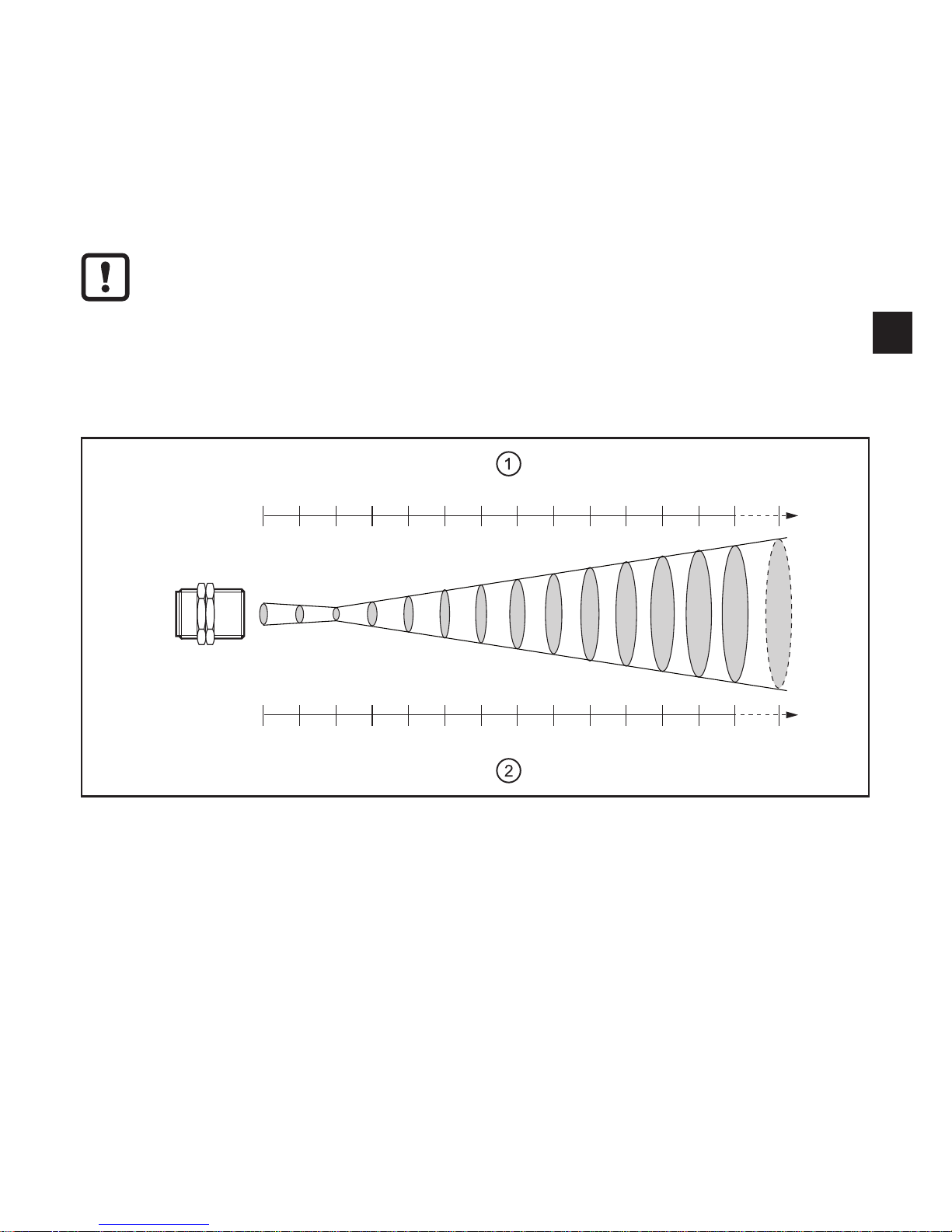
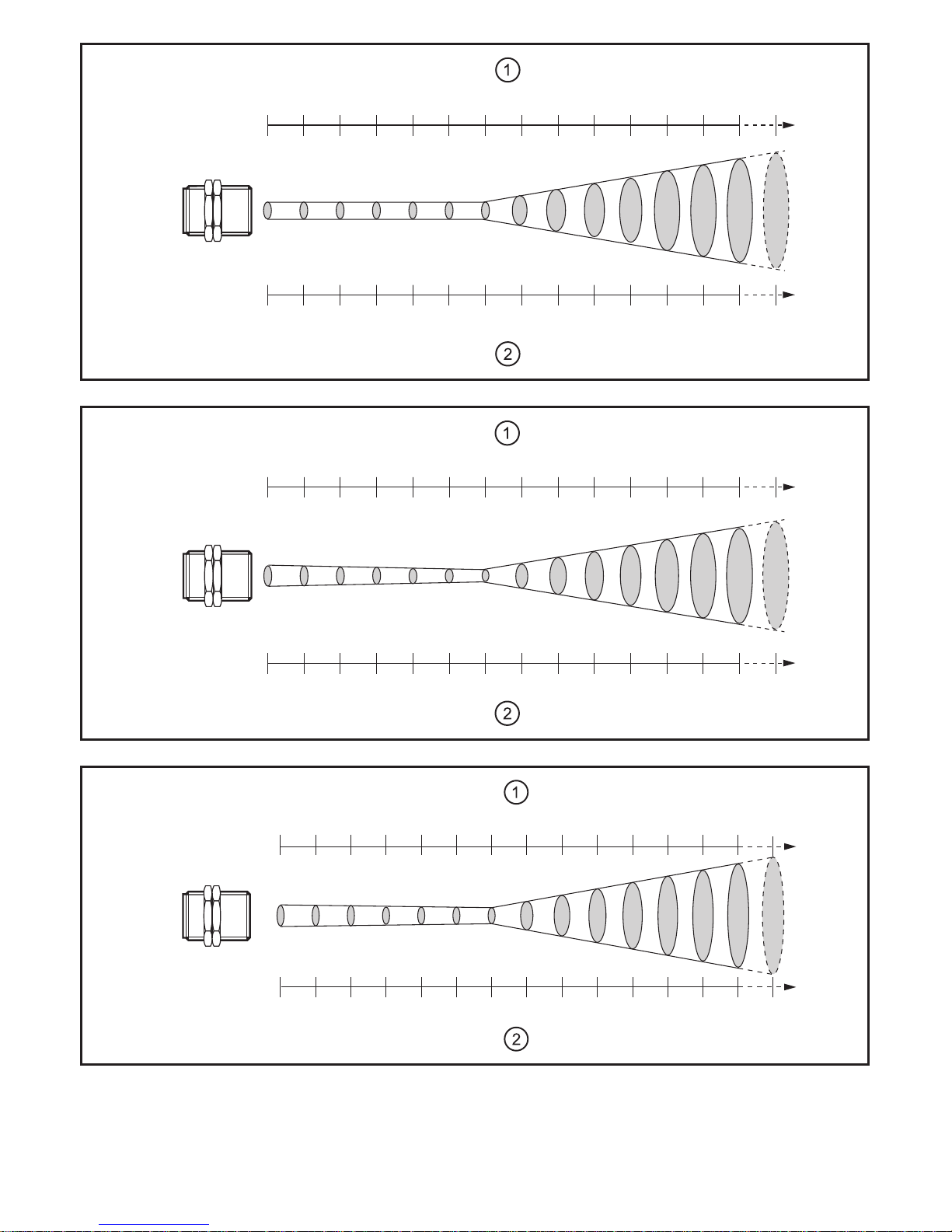
For correct orientation observe the measuring segment diameter (1) and the
measuring distance (2)� The object to be measured should not be smaller than the
measured spot diameter:
[mm]
200100 300 400 500 600 700 800 900 1000
2000 3000 4000 5000 ∞
[mm]
1315 11 20 29 39 48 57 66 75 167 259 350 442
TW2000
(1) Measuring segment diameter
(2) Measuring distance
Page 12
12
[mm]
[mm]
1212 12 12 12 12 12 20 28 36 44 52 60 68
200100 300 400 500 1000 1500 2000 2500 3000 3500 4000 4500 5000
TW2001
∞
[mm]
200100 300 400 500 1000 1500 2000 2500 3000 3500 4000 4500 5000
[mm]
14,214,6 13,8 13,4 13 11 9 17 25 33 41 49 57 65
∞
TW2002
[mm]
[mm]
∞
TW2011
20,4 20 19 19 18 15 12,5 24 35 46 57 68 80 91
100 200 300 400 500 1000 1500 2000 2500 3000
3500 4000 4500 5000
Page 13
13
UK
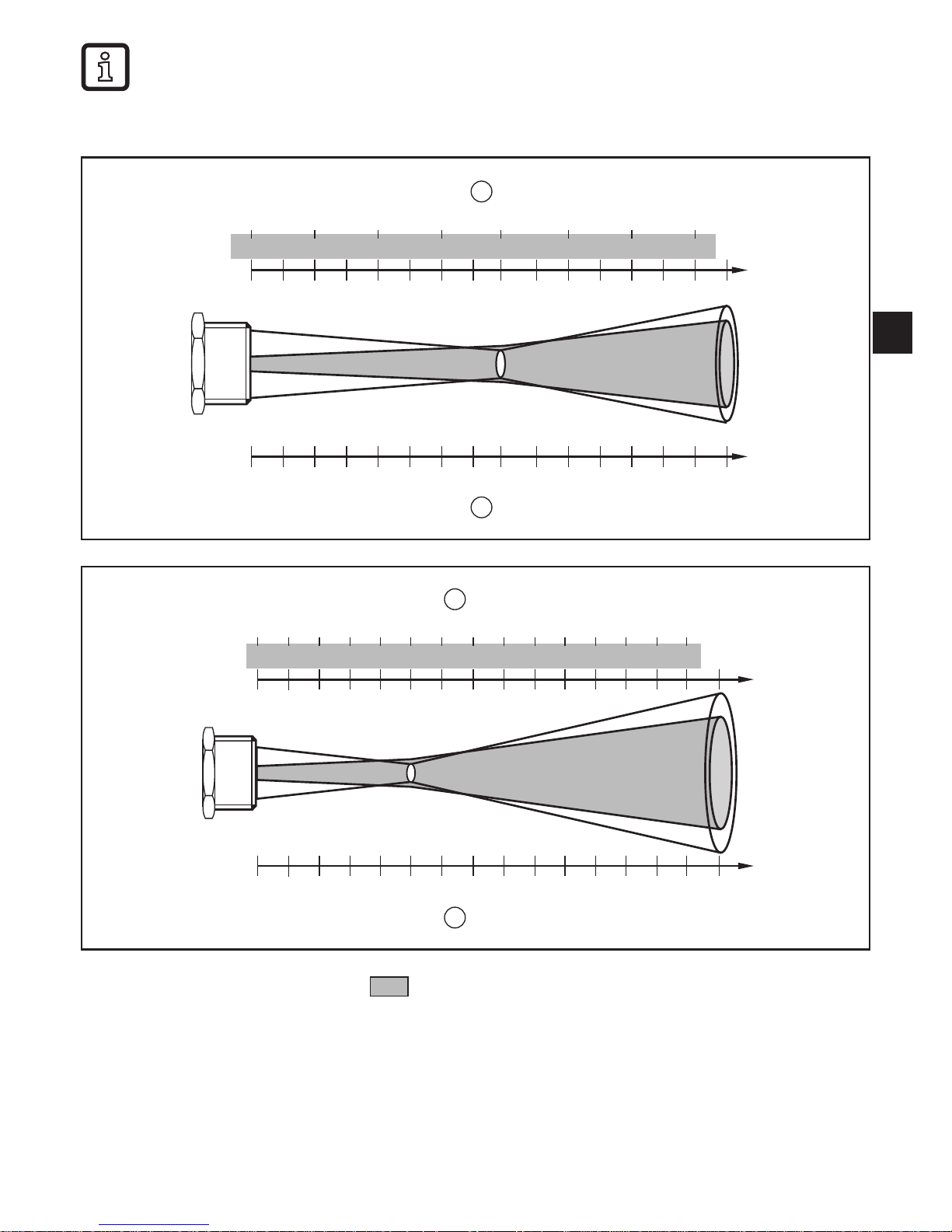
For types TW21xx:
► Align the measuring head so that the green LED pilot light is visible on
the object to be measured as a round light spot�
21,2 18,1 15 11,9 9 17,2 24,9
5 6,8 8,6 10,3 12 16,6 20,9
32,5
25,3
0 75 150 225 295 375 450 525
∞
1
[mm]
2
[mm]
TW2100
2
[mm]
1
[mm]
∞
18,2 15,9 13,6 11,3 9 6,7 11,7
506 7 8 9 10 13
16,71621,61926,62231,62536,62841,63146,53451,5
37
400 800 1200 1600 2000 2400 2800
TW2101
(1) Measuring segment diameter; Diameter LED pilot light
(2) Measuring distance
Page 14
14
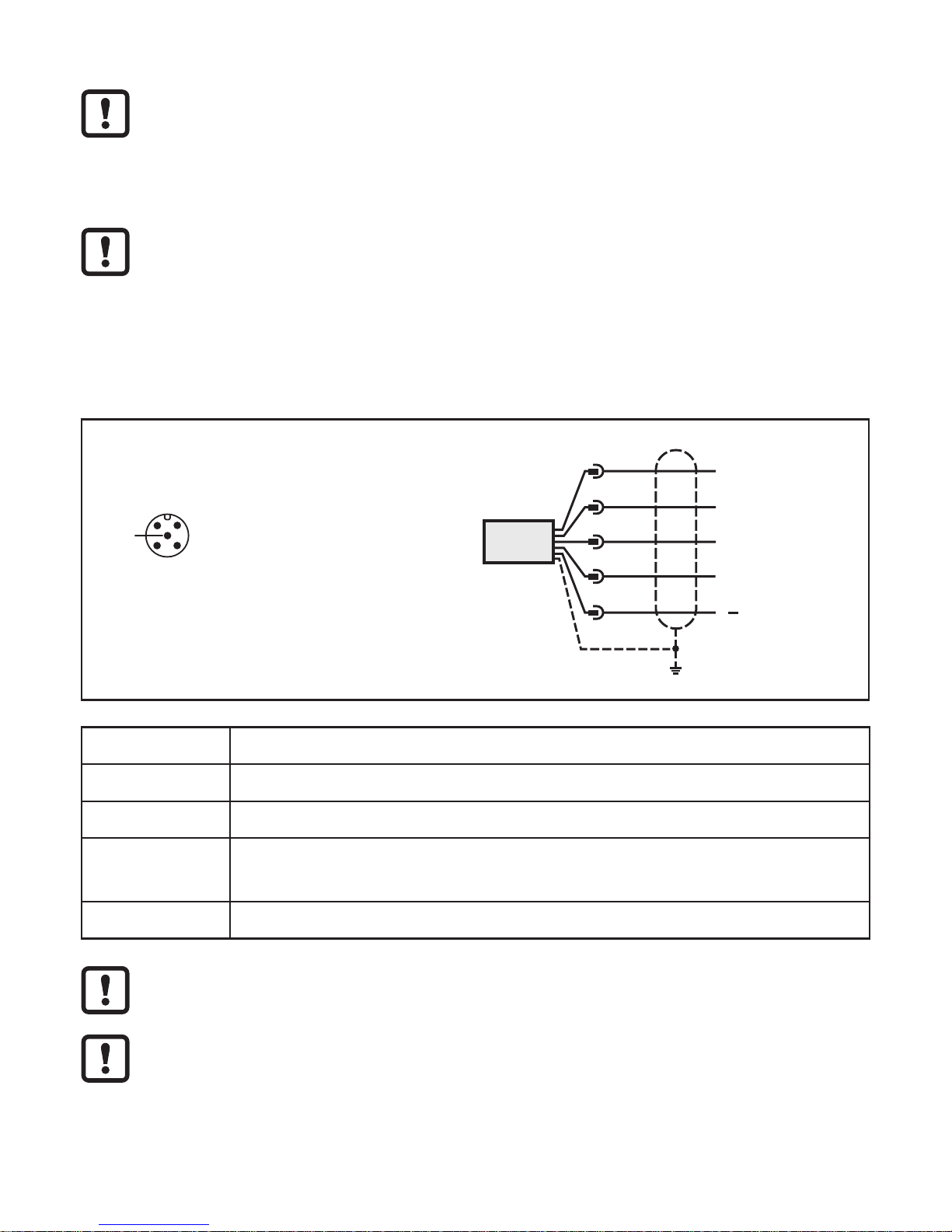
6 Electrical connection
The unit must be connected by a qualified electrician�
The national and international regulations for the installation of electrical
equipment must be adhered to�
Voltage supply according to EN 50178, SELV, PELV�
The unit is supplied with 24 V DC (18���32 V DC) low voltage�
The voltage supply must comply with the provisions of protective low
voltage EN 50178, SELV, PELV�
► Disconnect power�
► Connect the unit as follows:
4
2 1
3
5
BK: black
BN: brown
BU: blue
GY: grey
WH: white
Colours to DIN EN 60947-5-2
Pin 1 L+
Pin 2 (OUT2) analogue output
Pin 3 L-
Pin 4 (OUT1)
switching output
IO-Link
Pin 5 test input
► Use a screened cable� The screen of the cable must be connected to
the sensor housing�
When inductive loads are switched:
► Use a free wheel diode�
Page 15
15
UK
6.1 Screening and grounding
The unit housing is connected to the cable screen via the connector�
If there are potential differences between the grounding points, a compensation
current can flow across the screen connected at both sides� In this case, lay an
additional cable for equalisation of the potential�
To avoid compensation currents the unit can also be installed as isolated� The
screen must then be connected to the functional earth of the plant�
Without isolated installation and without potential equalisation the maximum
interference voltage on the infrared temperature sensor may be 32 V�
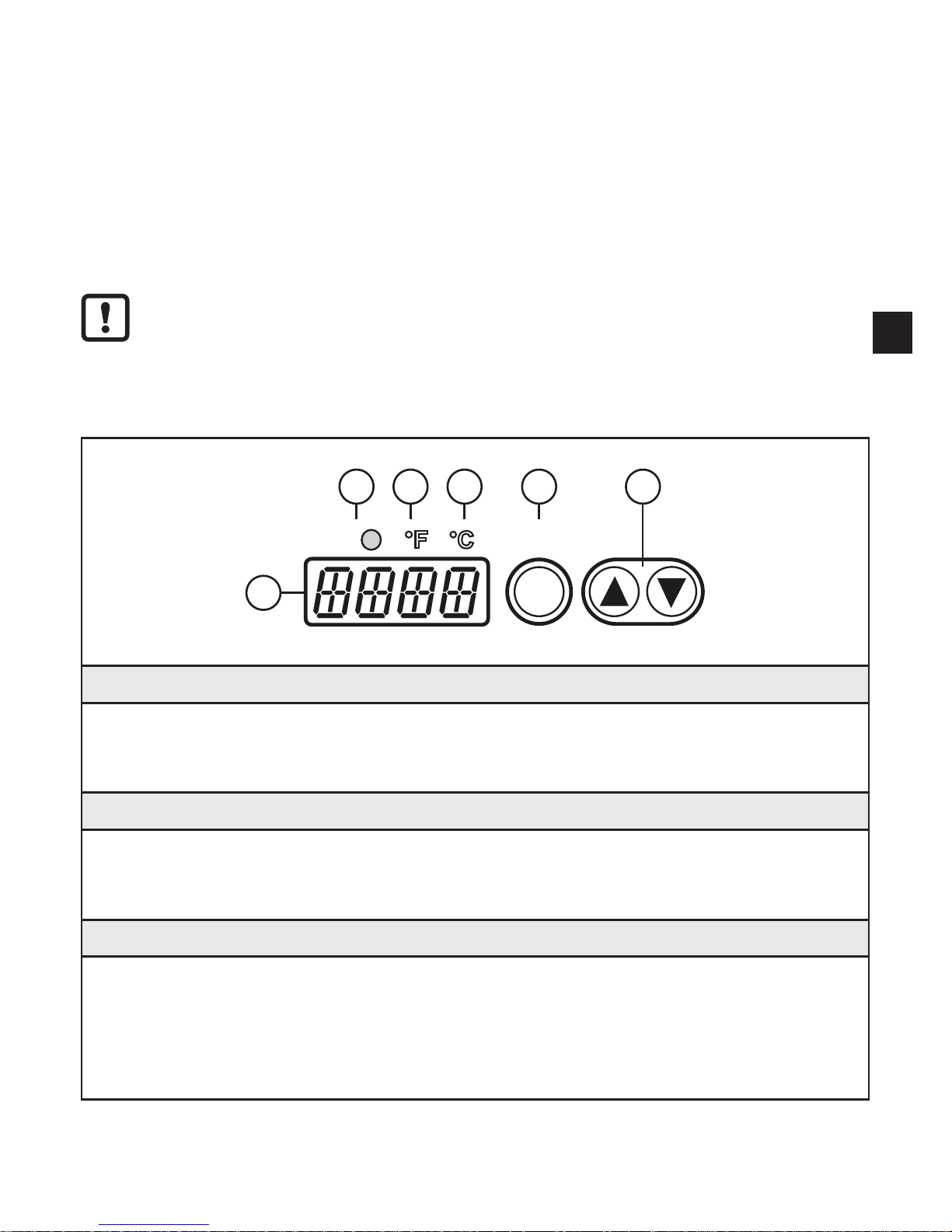
7 Operating and display elements
Out1 Enter
1
2
3
4
5
6
1 to 3: Indicator LEDs
LED 1 = switching status of the output
LED 2 = temperature indication in °F
LED 3 = temperature indication in °C
4: [Enter] button
• Selection of the parameters
• Reading the set values
• Confirmation of the parameter values
5: Set buttons [▲] and [▼]
• Selection of the parameters
• Activation of the setting functions
• Changing the parameter values
• Change of the display unit in the normal operating mode (RUN mode)
• Locking / unlocking
Page 16
16
6: Alphanumeric display, 4 digits
• Display of the temperature value
• Display of the parameters and configuration
• Error indication
8 Menu
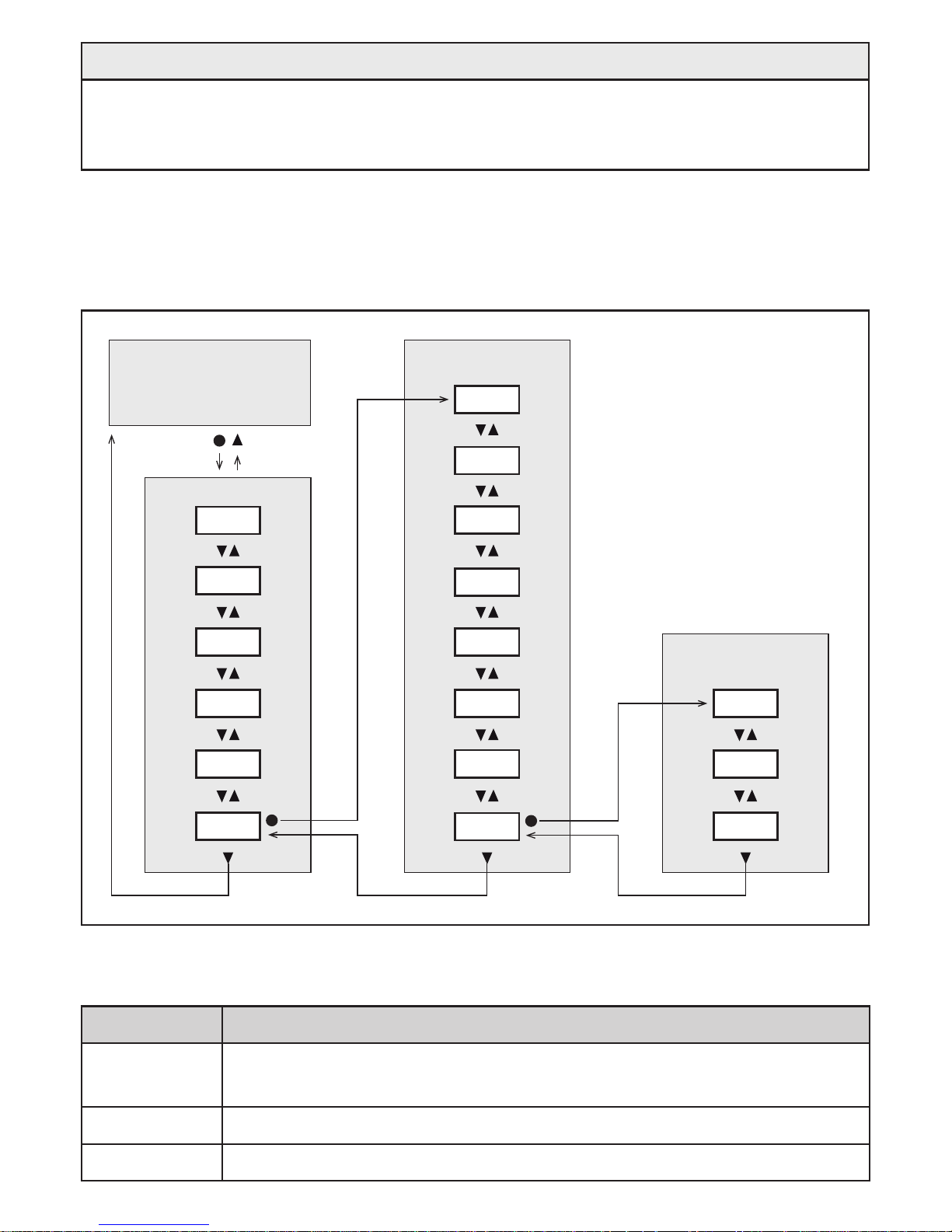
8.1 Menu structure
S.TMP
S.Tim
S.On
EF
SP1
EPSI
ASP2
AEP2
rP1
uni
dS1
rES
dr1
ou1
PhLd
SIM
dAP
EFRUN
SIM
°C / °F
8.2 Explanation main menu
Parameter Function and setting options
EPSI
Emissivity: Correction of the radiation characteristics of the object to be
measured
SP1 Switch point 1 = upper limit value for the switching output OUT1
rP1 Reset point = lower limit value for the switching output OUT1
Page 17
17
UK
ASP2
Analogue start point with scaled measuring range for the analogue output
OUT2
AEP2
Analogue end point with scaled measuring range for the analogue output
OUT2
EF Opening the lower menu level "Extended functions"
8.3 Explanation extended functions (EF)
Parameters Function and setting options
rES Reset to factory settings
dS1
Switch-on delay for OUT1:
Value in seconds (maximum 10 s in steps of 0�1 s)
dr1
Switch-off delay for OUT1:
Value in seconds (maximum 10 s in steps of 0�1 s)
ou1
Output function for OUT1:
- Hno: Hysteresis normally open
- Hnc: hysteresis normally closed
uni Standard unit of measurement for temperature: °F or °C
dAP
Damping for the temperature display, switching output and analogue
output
PhLd Configuration of the peak-hold function
SIM Opening of the lower menu level "Simulation"
8.4 Submenu simulation (SIM)
Parameter Function and setting options
S�TMP Simulated temperature value
S�Tim Duration of the simulation in minutes
S�On
Start of the simulation:
- On (simulation starts)
- OFF (simulation inactive)
Page 18

18
9 Set-up
When the supply voltage is switched on for the first time or after reset of the parameters to factory setting, [ ] is displayed� The emissivity has to be set:
► Press [Enter]�
[EPSI] is indicated in the display�
► Press [Enter]�
> [nonE] is indicated in the display�
► Press and hold [▼] until the requested value is indicated
► Press [Enter]
> The current temperature value is displayed� Now the unit operates permanently
with the set emissivity�
When the emissivity has been set and the supply voltage has been switched on,
the device performs an internal initialisation and self-diagnostics� After approx� 0�5
seconds the unit is ready for operation and starts the measurement and evaluation
function�
10 Parameter setting
Parameters can be set before installation or during operation�
If you change parameters during operation, this will influence the function
of the plant�
► Ensure that there will be no malfunctions in your plant�
During parameter setting the unit remains in the operating mode� It continues to
monitor with the existing parameter until the parameter setting has been completed�
The parameters can also be set via the IO-Link interface (→ 4.10 IO-Link)�
Page 19
19
UK
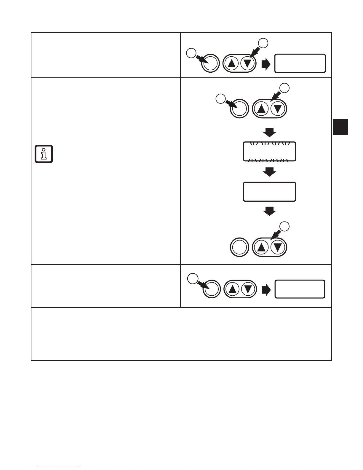
10.1 Parameter setting in general
Select parameter
1� Briefly press [Enter]�
2� Press [▲] or [▼] until the requested
parameter is displayed.
Enter
2
1
Changing the parameter value
3� Briefly press [Enter]�
> The currently set value is displayed�
4� Keep [▲] or [▼] pressed for 1 s._>
Display flashes first, then permanent�
5� Change value by pressing [▲] or [▼].
Keep [▲] or [▼] pressed.
> Faster cycle of the numerical
values�
4
5
3
Enter
Enter
Acknowledge parameter value
6� Briefly press [Enter]�
> The parameter is displayed again� The
new setting value is saved�
Enter
6
Finish parameter setting and change to the process value display:
► wait for 30 seconds
or
► change from the submenu to the main menu, from the main menu to the process value
display with [▲] or [▼].
Page 20
20
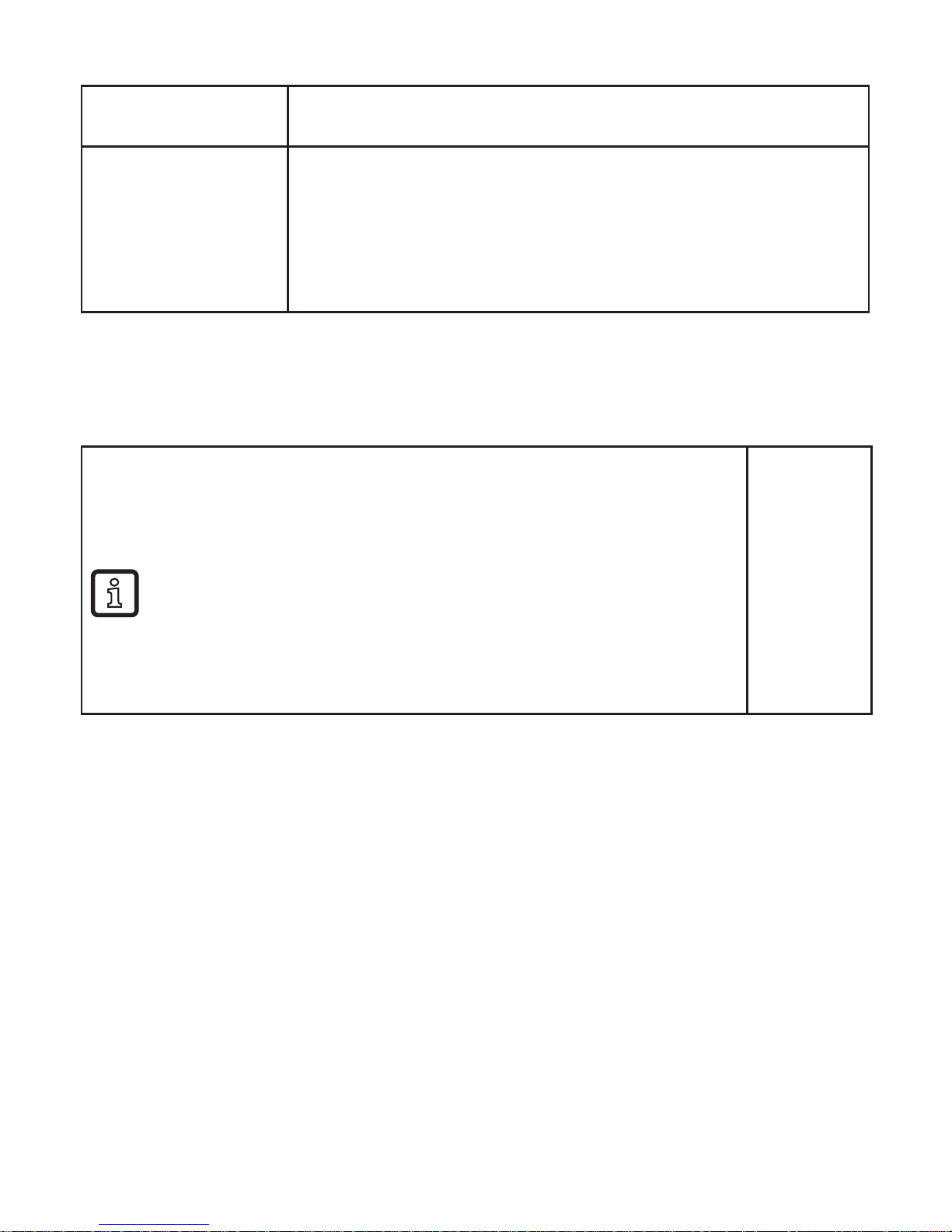
10.1.1 Switching between the menu levels
Change to the
submenu
► Select [EF] or [SIM] and switch to the submenu by pressing
[Enter]�
Back to the process
value display
► Change from the submenu to the main menu, from the main
menu to the process value display with [▲] or [▼]
or timeout:
► wait for 30 seconds
or escape function:
► press [▲] and [▼] simultaneously.
10.1.2 Locking / unlocking
The unit can be locked electronically to prevent unintentional settings� On delivery:
not locked�
Locking
► Make sure that the unit is in the normal operating mode�
► Press [▲] and [▼] simultaneously for 10 s.
> [Loc] is displayed�
During operation: [Loc] is briefly displayed if you try to change
parameter values�
Unlocking
► Press [▲] and [▼] simultaneously for 10 s.
> [uLoc] is displayed�
[Loc]
[uLoc]
10.1.3 Timeout
If no button is pressed for 30 s during parameter setting, the unit returns to the
operating mode with unchanged parameter�
Page 21
21
UK
10.2 Settings for temperature monitoring
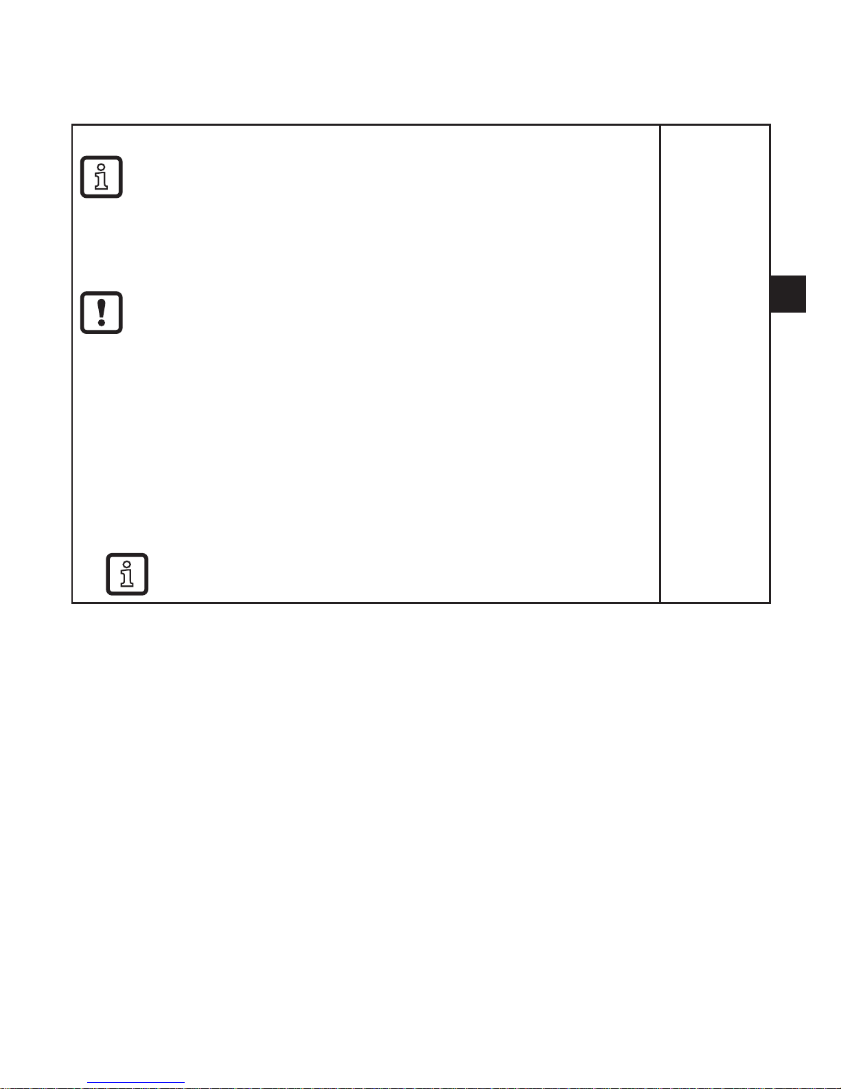
10.2.1 Setting the degree of emissivity
► Select [EPSI] and set the emissivity using [▲] or [▼].
When [▲] or [▼] is released, the changed target temperature
is displayed for approx� 2 s� After that, EPSI is displayed again�
Confirm the requested value with [Enter]�
TW2000 / TW2100 – Set emissivity with the supplied label (up to maximum 250 °C):
Ensure during the following measurements that the temperature of
the object to be measured remains constant�
► Select [EPSI] and set the emissivity to 94 %�
► Apply the label to the object to be measured and measure the tempera-
ture with the infrared temperature sensor (= reference temperature)�
► Remove the label and measure the temperature of the object again�
> Displayed temperature deviates from the reference temperature�
► Select [EPSI] and change the emissivity�
► Measure the object again�
► Repeat the process until the displayed value corresponds to the deter-
mined reference temperature�
Decreasing the emissivity leads to an increased temperature
display and vice versa�
Main menu:
[EPSI]
Page 22
22
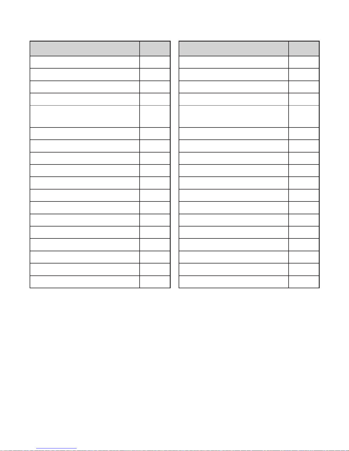
10.2.2 Emissivity for TW2000, TW2100
(λ = 8...14 μm)
Material [%] Material [%]
Alumina 76 Lime plaster 91
Asphalt 90���98 Clinker brick, glazed 75
Baking oven 96 Table stove 95
Concrete 55���65 Copper, oxidised 78
Bitumen
(roofing cardboard)
96 Plastics, opaque 65���95
Bread in the oven 88 Leather 75���80
Iron oxide 85���89 Marble 94
Enamel 84���88 Brass, oxidised 56���64
Soil 92���96 Paper 70���94
Paints and lacquers, shiny 92 Sand 90
Paints and lacquers, matt 96 Chamotte 75
Plaster 80���90 Black body 100
Glass 85���95 Steel, antirust 45
Graphite 98 Steel, red oxidised 69
Rubber, black 94 Textiles 75���88
Skin, human 98 Water 92���98
Radiator 80���85 Cement 90
Wood 80���90 Brick 93���96
Page 23

23
UK
10.2.3 Emissivities for TW2001, TW2101, TW2011, TW2002
TW2001, TW2101,
TW2011
(λ = 1.1...1.7 μm)
TW2002
(λ = 0.78...1.06 μm)
Material [%] [%]
Aluminium, polished 5 15
Aluminium, finished 10 25
Asbestos cement 60 70
Bronze, polished 1 3
Bronze, finished 15 30
Chromium, blank 15 30
Iron, heavily scaled 90 95
Iron, rolling skin 75 90
Iron, molten 15 30
Gold and silver 1 2
Graphite, finished 85 90
Copper, oxidised 70 90
Brass, oxidised (tarnished) 50 70
Nickel 8 20
Porcelain, glazed 50 60
Porcelain, rough 75 85
Soot 90 95
Chamotte 40 50
Slag 80 85
Black body 100 100
Pottery, glazed 85 90
Brick 85 90
zinc 40 60
Page 24

24
10.2.4 Settings for limit value monitoring with OUT1
► Select [ou1] and set the switching function:
- Hno = hysteresis function/NO,
- Hnc = hysteresis function/NC
► Select [SP1] and set the value at which the output is set�
► Select [rP1] and set the value at which the output is reset�
Menu EF:
[ou1]
Main menu:
[SP1]
[rP1]
10.2.5 Set the analogue signal for OUT2
► Select [ASP2] and set the value at which the minimum value is provided�
► Select [AEP2] and set the value at which the maximum value is provid-
ed�
Main menu:
[ASP2]
[AEP2]
10.3 User settings (optional)
10.3.1 Set the standard unit of measurement for temperature
► Select [uni] and set the unit of measurement: [°C or °F]�
Menu EF:
[uni]
10.3.2 Set delay time for OUT1
[dS1] = switch-on delay, [dr1] = switch-off delay�
► Select [dS1] or [dr1] and set a value in seconds (at 0�0 the delay time is
not active)�
Menu EF:
[dS1]
[dr1]
10.3.3 Set the measured value damping
► Select [dAP] and set a damping constant in seconds: 0���600 s in steps
of 0�1 s�
Menu EF:
[dAP]
10.3.4 Set the peak-hold function
► Select [Phld] and set the hold time in seconds:
0���600 s in steps of 0�1 s�
Menu EF:
[PhLd]
10.3.5 Setting the simulation function
► Select [S�TMP] and set the temperature value to be simulated�
► Select [S�Tim] and set the time of the simulation in minutes�
► Select [S�On] and set the function:
- On: The simulation starts� The values are simulated for the time set
at [S�Tim]� SIM]is displayed simultaneously with the process values�
Cancel with [Enter]�
- OFF: The simulation is not active�
Menu SIM:
[S�TMP]
[S�Tim]
[S�On]
Page 25
25
UK
10.4 Service functions
10.4.1 Reset all parameters to factory setting
► Select [rES]�
► Briefly press [Enter]�
► Keep [▲] or [▼] pressed.
> [----] is displayed�
► Briefly press [Enter]�
> [ ] is displayed� The emissivity has to be reset (→ 10.2.1)�
We recommend taking down your own settings in a table before carrying out
a reset (→ 15 Factory setting)�
Menu EF:
[rES]
11 Operation
11.1 Changing the display unit in the Run mode
The temperature is displayed in the set standard unit of measurement (→ 10.3.1)�
The display unit can be changed by pressing the pushbutton:
► Briefly press [▼] or [▲] in the Run mode.
> The process value is displayed in the other temperature unit for 30 s; the
respective LED is lit�
11.2 Read the set parameters
► Briefly press [Enter]�
► Press [▼] or [▲] until the required parameter is displayed.
► Briefly press [Enter]�
> The unit displays the currently set parameter value for 30 seconds� Then it
returns to the Run mode�
12 Technical data and scale drawing
Technical data and scale drawing at www�ifm�com�
Page 26

26
13 Troubleshooting
Display Error
[SC1] flashes at 2 Hz
LED OUT1 flashes at 4 Hz
Overload switching output
[ot] and the process value
change at 0�5 Hz
Overtemperature in the unit (> 75 °C)
[
ot
] and the process value
change with 0�5 Hz
LED OUT1 flashes at 4 Hz
Overtemperature in the unit (> 120 °C)
> The switching output is deactivated�
LED OUT1 flashes at 2 Hz Faulty connection of the supply voltage
No display Supply voltage too low
[UL] Measuring range not reached
[OL] Measuring range exceeded
14 Maintenance, repair and disposal
A soiled lens leads to a wrong display of the measured value�
► Check the lens regularly and clean it, if required:
- Remove dust by blowing or use a soft brush�
- Use clean, soft and lint-free cloths or those offered on the market for lens
cleaning�
- For heavier contamination, use washing-up liquid or liquid soap� Then carefully rinse with clear water� Hold the lens downwards�
- Exert only little pressure on the lens during cleaning to avoid scratches�
Page 27
27
UK
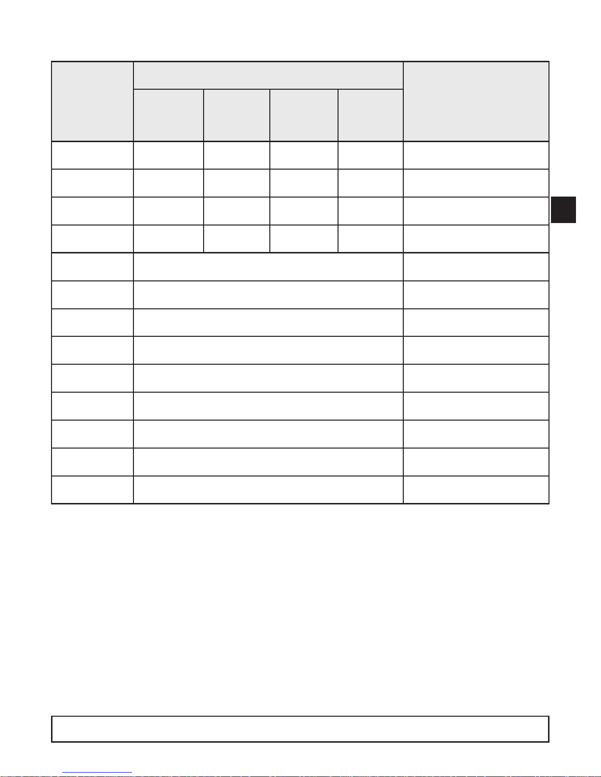
15 Factory setting
Parameter Factory setting User setting
TW2000
TW2100
TW2001
TW2101
TW2002 TW2011
SP1 250 °C 500 °C 1000 °C 550 °C
rP1 230 °C 480 °C 960 °C 530 °C
ASP2 0 °C 250 °C 500 °C 300 °C
AEP2 1000 °C 1600 °C 2500 °C 1600 °C
rES -
dS1 0�0 s
dr1 0�0 s
ou1 Hno
uni °C
dAP 0�0 s
PhLd 0
EPSI None
tESt OFF
More information at www�ifm�com
 Loading...