

IFM Electronic TR7439 Operating Instructions Manual

Operating instructions
Control monitor for temperature sensors
TR7439
80231577 / 00 03 / 2016
UK

2
Contents
1 Safety instructions �����������������������������������������������������������������������������������������������3
2 Functions and features ����������������������������������������������������������������������������������������3
3 Function ��������������������������������������������������������������������������������������������������������������� 4
3�1 Switching function ������������������������������������������������������������������������������������������ 4
3�2 Display colour change �����������������������������������������������������������������������������������5
3�2�1 Parameter r1ou, r2ou, G1ou, G2ou ������������������������������������������������������ 5
3�2�2 Parameter r-cF, G-cF ���������������������������������������������������������������������������� 6
3�2�3 Parameter r-12, G-12 ���������������������������������������������������������������������������6
3�3 IO-Link �����������������������������������������������������������������������������������������������������������7
3�3�1 General information ������������������������������������������������������������������������������7
3�3�2 Device-specific information �������������������������������������������������������������������7
3�3�3 Parameter setting tools �������������������������������������������������������������������������7
4 Installation������������������������������������������������������������������������������������������������������������7
5 Electrical connection �������������������������������������������������������������������������������������������� 8
5�1 Sample circuits for connection of TR7439 �����������������������������������������������������9
5�2 Connection for temperature sensor ���������������������������������������������������������������9
6 Operating and display elements ������������������������������������������������������������������������10
7 Menu ������������������������������������������������������������������������������������������������������������������ 11
7�1 Process value display (RUN) and menu structure ��������������������������������������� 11
7�2 Explanation of the menu ������������������������������������������������������������������������������ 12
8 Parameter setting ����������������������������������������������������������������������������������������������13
8�1 Parameter setting in general �����������������������������������������������������������������������14
8�1�1 Change between the menus ���������������������������������������������������������������14
8�1�2 Change to the process value display (RUN mode) ����������������������������14
8�1�3 Locking / Unlocking ����������������������������������������������������������������������������15
8�1�4 Timeout �����������������������������������������������������������������������������������������������15
8�1�5 Configure colour change display �������������������������������������������������������15
8�1�6 Setting of the limit values for colour change ��������������������������������������� 15
8�1�7 Resetting all parameters to factory setting �����������������������������������������15
8�1�8 Read the min/max values �������������������������������������������������������������������16
9 Operation ����������������������������������������������������������������������������������������������������������� 16
9�1 Reading of the set parameters ��������������������������������������������������������������������16

3
UK
Technical data, approvals, accessories and further information
at www�ifm�com�
1 Safety instructions
• Please read this document prior to set-up of the unit� Ensure that the product is
suitable for your application without any restrictions�
• If the operating instructions or the technical data are not adhered to, personal
injury and/or damage to property can occur�
• Improper or non-intended use may lead to malfunctions of the unit or to unwanted effects in your application� That is why installation, electrical connection,
set-up, operation and maintenance of the unit must only be carried out by
qualified personnel authorised by the machine operator�
• Check the compatibility of the product materials (→ Technical data) with the
media to be measured in all applications�
• The responsibility whether the measurement devices are suitable for the respective application lies with the operator� The manufacturer assumes no liability
for consequences of misuse by the operator� Improper installation and use of
the devices result in a loss of the warranty claims�
2 Functions and features
With temperature sensors connected the unit monitors the system temperature in
machinery and plant�
Connectable temperature sensors:
- Temperature sensors TM, TS or TT�
- Resistance thermometer RTD (Pt 100 or Pt 1000)�
The unit automatically detects the connected sensor type and configures itself
accordingly�
The electrical measuring method (3-wire or 4-wire sensor) is determined via the
menu setting and used bridge(s) (→ 7.2)�
9�2 Error indications / self-diagnostics ��������������������������������������������������������������� 16
10 Technical data �������������������������������������������������������������������������������������������������� 17
11 Factory setting �������������������������������������������������������������������������������������������������17
4
3 Function
• The unit displays the current system temperature�
• It features an IO-Link interface and is designed for full bidirectional communication�
• The unit generates 2 output signals according to the parameter setting:
- OUT1/IO-Link: Switching signal, limit values for temperature
- OUT2: Switching signal, limit values for temperature
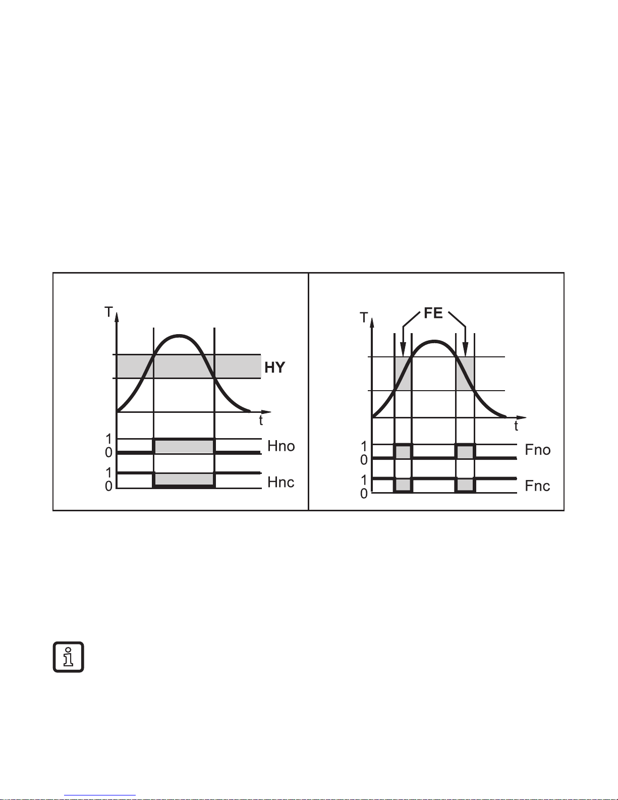
3.1 Switching function
OUTx changes its switching status if it is above or below the set switching limits�
Hysteresis or window function can be selected�
Hysteresis function Window function
SPx
rPx
FHx
FLx
T = Temperature
SPx = set point (SP1 / SP2)
rPx = reset point (rP1 / rP2)
HY = hysteresis
Hno = Hysteresis NO (normally open)
Hnc = Hysteresis NC (normally closed)
T = Temperature
FHx = upper limit value (FH1 / FH2)
FLx = lower limit value (FL1 / FL2)
FE = window
Fno = Window NO (normally open)
Fnc = Window NC (normally closed)
When the hysteresis function is set, the set point (SPx) is defined first and
then the reset point (rPx) which must be of a lower value� If only the set
point is changed, the reset point remains constant�
5
UK
When set to the window function the upper limit value (FHx) and the lower
limit value (FLx) have a fixed hysteresis of 0�25 % of the final value of the
measuring range� This keeps the switching state of the output stable if the
temperature varies slightly�
3.2 Display colour change
The colour of the characters in the display can be set via the parameter [colr]�
With the parameters rED (red) and GrEn (green), the display is permanently set to
one colour� Via further parameters, the colour of the characters changes according
to the measured value:
OUT1 OUT2 OUT1 and OUT2 Colour change to���
Parameter r1ou r2ou r-cF, r-12 red
G1ou G2ou G-cF, G-12 green
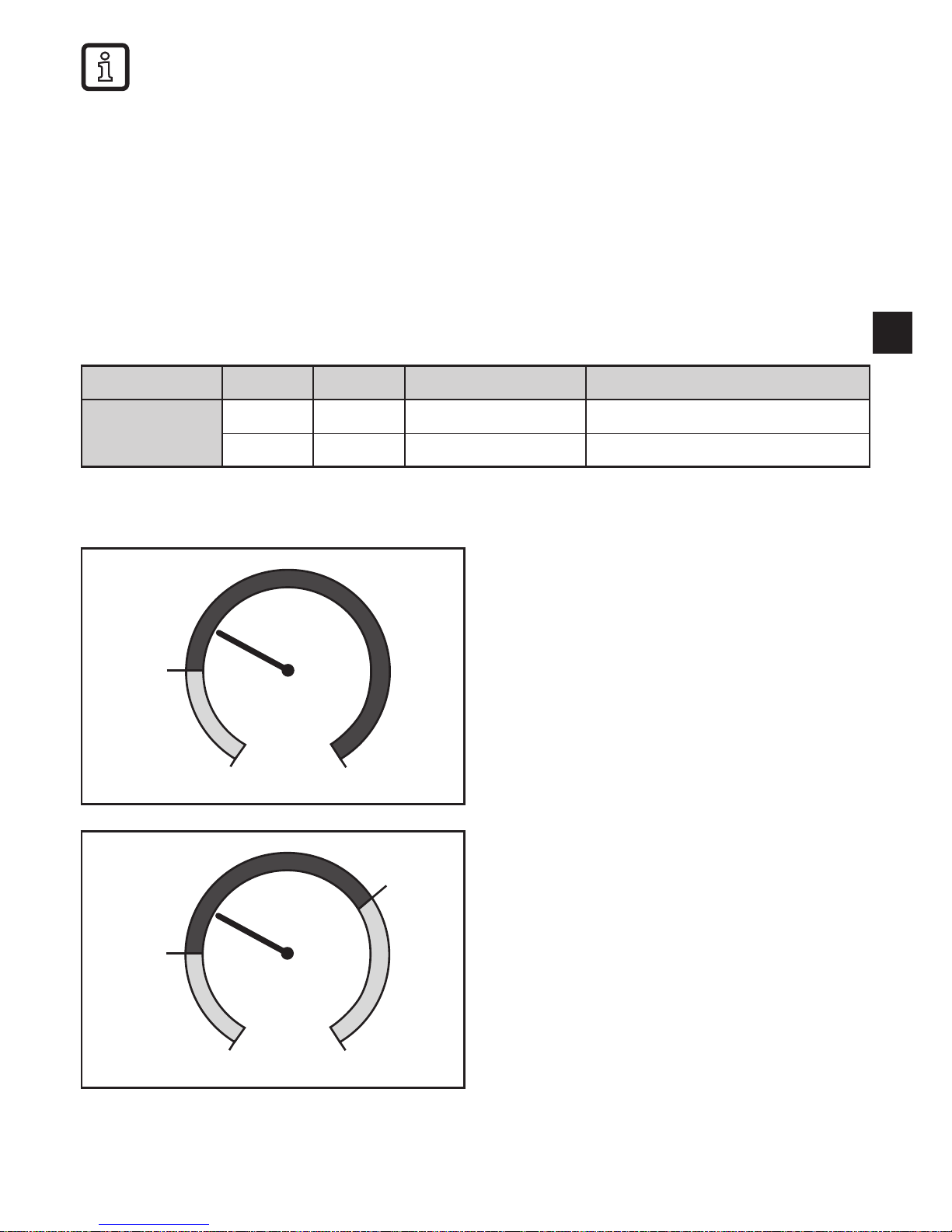
3.2.1 Parameter r1ou, r2ou, G1ou, G2ou
SP1/
SP2
MAW MEW
Hysteresis function:
Colour change if measured value
is above the switch point
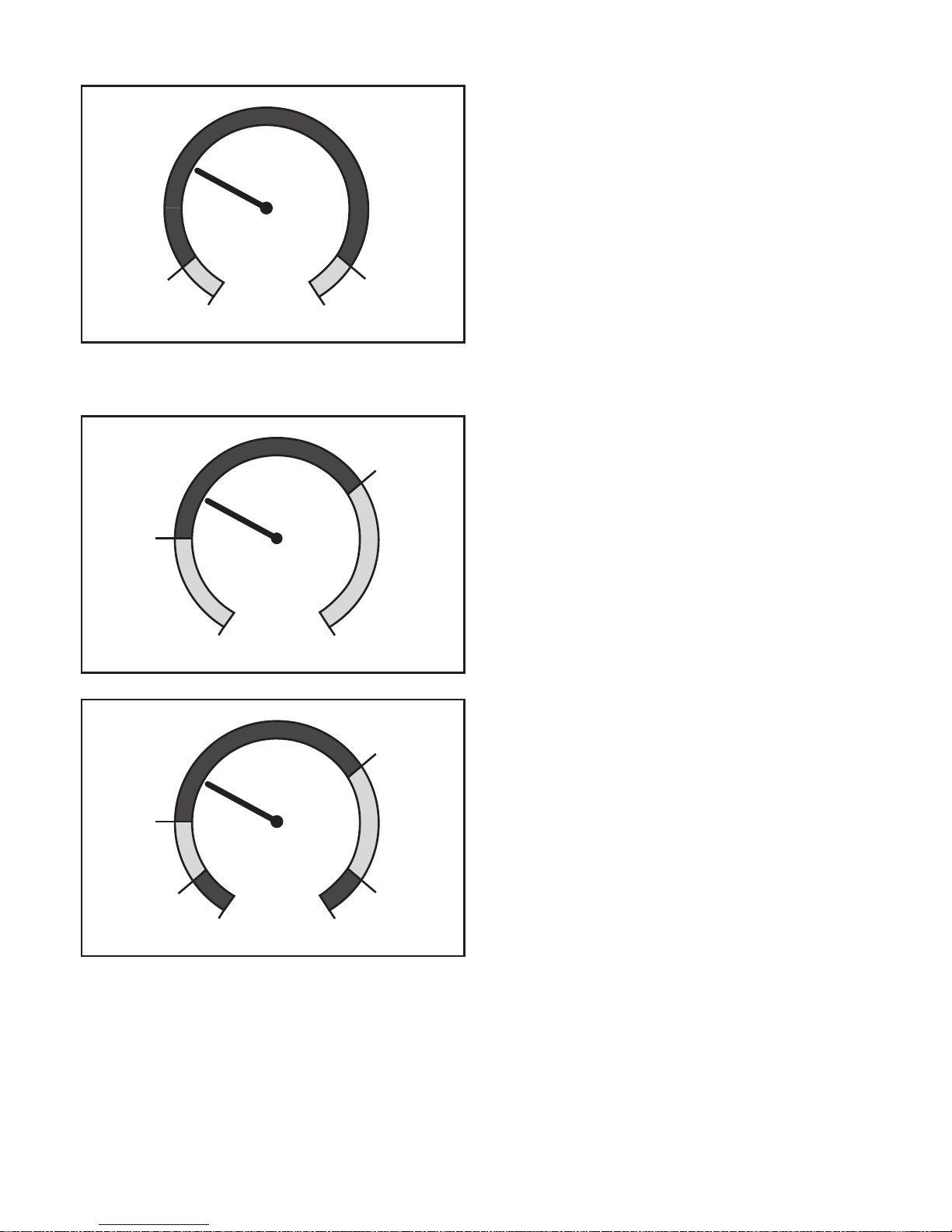
FL1/
FL2
FH1/
FH2
MAW MEW
Window function:
Colour change if measured value
is within the window range
MAW = initial value of the measuring range
MEW = final value of the measuring range
6
3.2.2 Parameter r-cF, G-cF
cFL cFH
MAW MEW
Colour change if the measured value
is within definable limits�
3.2.3 Parameter r-12, G-12
SP1
SP2
MAW MEW
Both outputs hysteresis function:
Colour change if the measured value
is between SP1 and SP2�
FL1
FH1
FL2
FH2
MAW MEW
Both outputs window function:
Colour change if the measured value
is between the window ranges�
 Loading...