

Page 1
Installation Instructions
Tel:
+44
(0)191 490 1547
Fax:
+44 (0)191 477 5371
Email:
northernsales@thorneandderrick.co.uk
Website: www.heattracing.co.uk
www.thorneanderrick.co.uk
Temperature transmitter
TA3130
UK
701926 / 01 12 / 2012
Page 2
1 Functions and features
The temperature transmitter detects the current system temperature and converts
it into an analogue output signal (4 ... 20 mA).
• Measuring range: 0 ... 140°C / 32 ... 284°F
• Measuring element: Pt 1000 to DIN EN 60751, class A
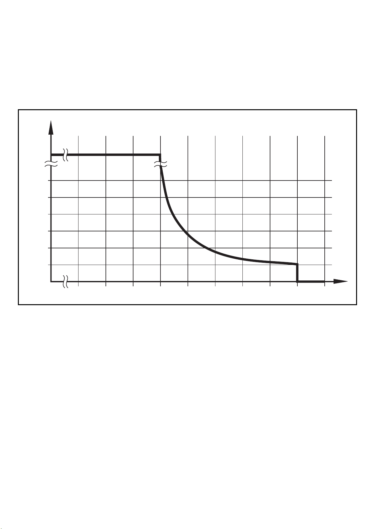
• Temperature resistance
[min]
¥
240
200
160
120
80
40
0
110 115 120 125 130 135 140 145 150
Maximum operation time depending on the medium temperature
[°C]
155
2
Page 3

2 Installation
Tel:
+44
(0)191 490 1547
Fax:
+44 (0)191 477 5371
Email:
northernsales@thorneandderrick.co.uk
Website: www.heattracing.co.uk
www.thorneanderrick.co.uk
► Insert the unit in a G ¼ process
connection.
► Tighten firmly.
UK
3 Electrical connection
The unit must be connected by a suitably qualified electrician.
The national and international regulations for the installation of electrical
equipment must be observed.
Voltage supply to EN50178, SELV, PELV.
Referring to UL: For use on a low voltage circuit with overcurrent protec-
tion in accordance with UL873 Tab. 28.1 or Imax = 100/Ub (Ub = voltage
of the circuit).
► Disconnect power.
► Connecting the unit as follows:
1
2
3
4
1
2
4
3
BN
WH
BK
BU
L
Ln.c.
n.c.
+
Core colours of ifm sockets:
1 = BN (brown), 2 = WH (white), 3 = BU (blue), 4 = BK (black)
n.c. = not connected
3
 Loading...