

IFM Electronic SU7000, SU8000, SU9000 Operating Instructions Manual

Operating instructions
Ultrasonic flow rate sensor
SU7000
SU8000
SU9000
80011616 / 00 11 / 2014
UK

2
Contents
1 Preliminary note ��������������������������������������������������������������������������������������������������� 4
1�1 Symbols used ������������������������������������������������������������������������������������������������4
1�1 Warning signs used ���������������������������������������������������������������������������������������4
2 Safety instructions �����������������������������������������������������������������������������������������������4
3 Functions and features ����������������������������������������������������������������������������������������5
4 Function ��������������������������������������������������������������������������������������������������������������� 6
4�1 Process measured signals ����������������������������������������������������������������������������6
4�2 Volumetric flow monitoring �����������������������������������������������������������������������������6
4�3 Consumed quantity monitoring (totaliser function) ����������������������������������������6
4�3�1 Consumed quantity monitoring with pulse output ��������������������������������� 7
4�3�2 Consumed quantity monitoring with preset counter �����������������������������7
4�4 Temperature monitoring ��������������������������������������������������������������������������������� 7
4�5 Volumetric flow or temperature monitoring / switching function ���������������������7
4�5�1 Hysteresis function �������������������������������������������������������������������������������8
4�5�2 Window function �����������������������������������������������������������������������������������8
4�6 Volumetric flow or temperature monitoring / analogue function ���������������������9
4�6�1 Voltage output 0 ��� 10 V (example volumetric flow monitoring) ������������9
4�6�2 Current output 4 ��� 20 mA (example volumetric flow monitoring) �������10
4�7 Start-up delay ����������������������������������������������������������������������������������������������10
4�8 Customer-specific calibration (CGA) �����������������������������������������������������������13
5 Installation����������������������������������������������������������������������������������������������������������14
5�1 Recommended mounting position ���������������������������������������������������������������14
5�2 Non recommended installation position �������������������������������������������������������15
5�3 Installation in pipes ��������������������������������������������������������������������������������������16
6 Electrical connection ������������������������������������������������������������������������������������������ 16
7 Operating and display elements ������������������������������������������������������������������������18
8 Menu ������������������������������������������������������������������������������������������������������������������ 20
8�1 Menu structure ��������������������������������������������������������������������������������������������� 20
8�2 Explanation of the menu ������������������������������������������������������������������������������ 21
9 Set-up ����������������������������������������������������������������������������������������������������������������22
10 Parameter setting ��������������������������������������������������������������������������������������������22
10�1 Parameter setting in general ���������������������������������������������������������������������23
4
1 Preliminary note
1.1 Symbols used
► Instructions
> Reaction, result
[…] Designation of keys, buttons or indications
→ Cross-reference
Important note
Non-compliance can result in malfunction or interference�
1.1 Warning signs used
CAUTION
Warning of personal injury�
Slight reversible injuries may result�
2 Safety instructions
• Please read this document prior to set-up of the unit� Ensure that the product is
suitable for your application without any restrictions�
• If the operating instructions or the technical data are not adhered to, personal
injury and/or damage to property can occur�
• Improper or non-intended use may lead to malfunctions of the unit or to unwanted effects in your application� That is why installation, electrical connection, set-up, operation and maintenance of the unit must only be carried out by
qualified personnel authorised by the machine operator�
• In order to guarantee the correct condition of the device for the operating time it
is necessary to use the device only for media to which the wetted materials are
sufficiently resistant (→ Technical data).
• The responsibility whether the measurement devices are suitable for the
respective application lies with the operator� The manufacturer assumes no
12 Technical data �������������������������������������������������������������������������������������������������� 31
13 Factory setting �������������������������������������������������������������������������������������������������32

5
UK
liability for consequences of misuse by the operator� Improper installation and
use of the devices results in a loss of the warranty claims�
• For medium temperatures above 50 °C some parts of the housing can heat up
to over 65 °C� Moreover, during installation or in case of a fault (e�g� housing
damage) media under high pressure or hot media can leak from the system� To
avoid personal injury, take the following measures:
► Install the unit according to the applicable rules and regulations�
► Ensure that the system is free of pressure during installation�
► Protect the housing against contact with flammable substances and
unintentional contact� To do so, equip the unit with suitable protection (e�g�
protective cover)�
► Do not press the pushbuttons manually; instead use another object (e�g�
ballpoint pen)�
3 Functions and features
Pressure Equipment Directive (PED): The units comply with section 3, article 3 of
the Directive 97/23/EC and must be designed and manufactured for non-superheated liquids of group 2 fluids in accordance with the sound engineering practice�
The unit monitors liquid media�
It detects the 3 process categories volumetric flow, consumed quantity, medium
temperature�
Application area
• Water
• Glycol solutions
• Low viscosity oils (viscosity: 7���40 mm²/s at 40°C)
• High viscosity oils (viscosity: 30���68 mm²/s at 40°C)
Selection of the medium to be monitored → 10.5.9�

6
4 Function
4.1 Process measured signals
The unit displays the current process values�
It generates 2 output signals according to the parameter setting�
OUT1: 3 selection options Parameter setting
- Switching signal for volumetric flow quantity limit value (→ 10.2.1)
- or pulse signal for quantity meter (→ 10.3.1)
- or switching signal for preset counter (→ 10.3.2)
OUT2: 4 selection options Parameter setting
- Switching signal for volumetric flow quantity limit value (→ 10.2.2)
- or switching signal for temperature limit value (→ 10.4.1)
- or analogue signal for volumetric flow quantity (→ 10.2.3)
- or analogue signal for temperature (→ 10.4.2)
- or input for external reset signal (InD) (→ 10.3.7)
If not used as an output, OUT2 (pin 2) can instead be used
as an input for an external reset signal
(→ 10.3.7)
4.2 Volumetric flow monitoring
The volumetric flow is monitored by an ultrasonic measuring system, the measured signals are evaluated by the electronics�
The signals for measuring the volumetric flow quantity can be provided as follows:
1� Two switching signals for volumetric flow quantity limit values on output 1 and
output 2 (→ 4.5)�
2� An analogue signal proportional to the volumetric flow (4���20 mA or 0���10 V)
on output 2 (→ 4.6)�
4.3 Consumed quantity monitoring (totaliser function)
The unit has an internal quantity meter which continuously totals the volumetric
flow quantity� The sum corresponds to the current consumed quantity since the
last reset�
• The current meter reading can be displayed�
• In addition the value before the last reset is saved� This value can also be
displayed�

7
UK
The meter saves the totalled consumed quantity every 10 minutes� After
a power failure this value is available as the current meter reading� If a
time-controlled reset is set, the elapsed time of the set reset interval is
also saved� So the possible data loss can be maximum 10 minutes�
The meter can be reset as follows:
→ 10.3.4 Manual counter reset�
→ 10.3.5 Time-controlled counter-reset�
→ 10.3.7 Configure meter reset using an external signal�
4.3.1 Consumed quantity monitoring with pulse output
Output 1 indicates a counting pulse when the set volumetric flow quantity has
been reached (→ 10.3.1)�
4.3.2 Consumed quantity monitoring with preset counter
Output 1 switches when the set volumetric flow quantity has been reached (→
10�3�2)� 2 types of monitoring are possible:
1� Time-dependent quantity monitoring (→ 10.3.5 Time-controlled counter-reset):
- If the quantity x is reached during t, output 1 switches and remains switched
until the counter is reset�
- If the quantity x is not reached after the time t has elapsed, the meter is automatically reset and counting starts again; output 1 does not switch�
2� Non time-dependent quantity monitoring (→ 10.3.6 Deactivate meter reset)
- If the quantity x is reached, output 1 switches and remains switched until the
counter is reset�
4.4 Temperature monitoring
The following signals are provided for temperature monitoring:
1� A switching signal for temperature limit values on output 2 (→ 4.5)�
2� An analogue signal proportional to the temperature (4���20 mA or 0���10 V) on
output 2 (→ 4.6)�
4.5
Volumetric flow or temperature monitoring / switching
function
OUTx changes its switching status if it is above or below the set switching limits
(SPx, rPx)� The following switching functions can be selected:
8
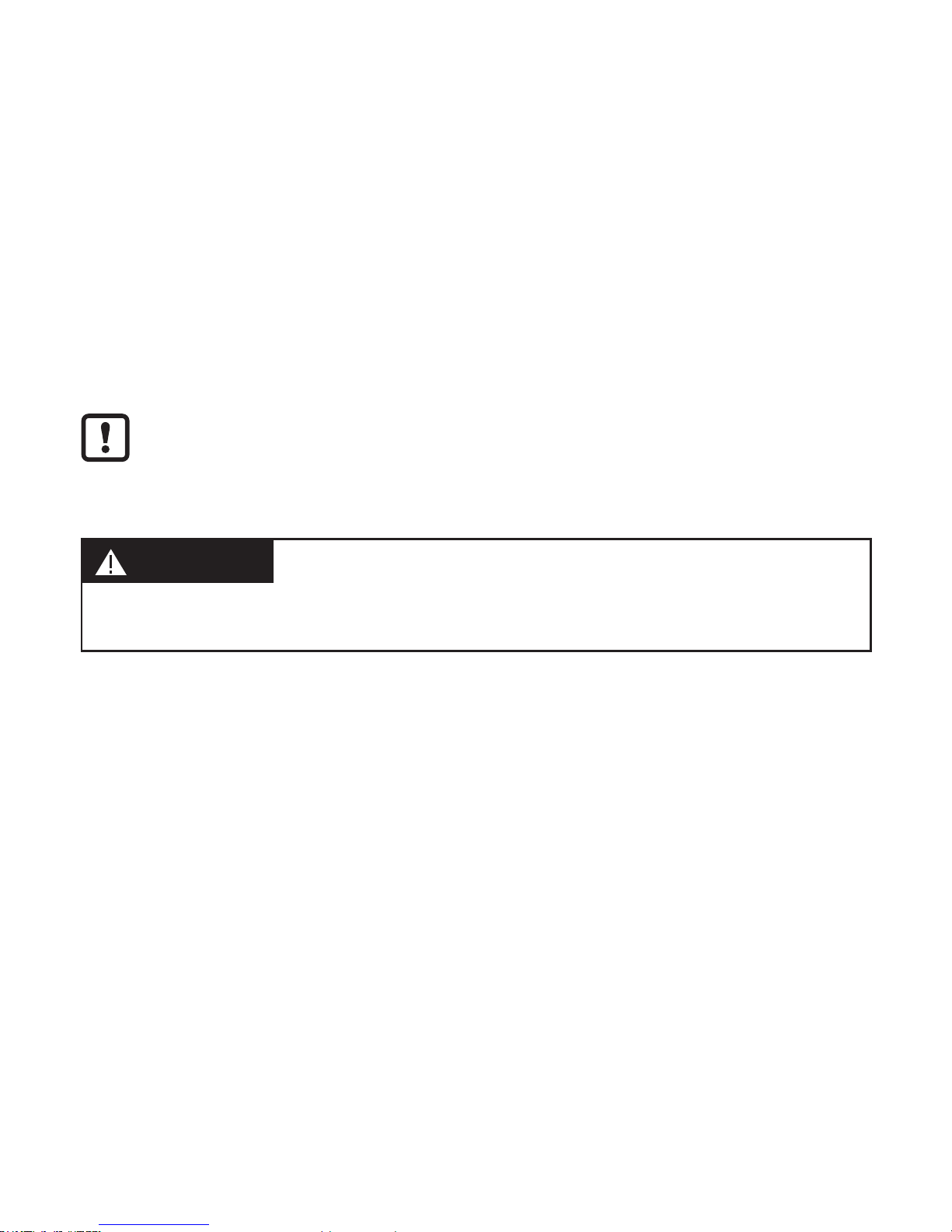
4.5.1 Hysteresis function
SP
rP
Normally open: [OUx] = [Hno]
Normally closed: [OUx] = [Hnc]
First the set point (SPx) is set, then the
reset point (rPx) with the requested
difference�
When SPx is adjusted, rPx is
changed automatically; the difference remains constant�
Example of volumetric flow monitoring
HY = hysteresis
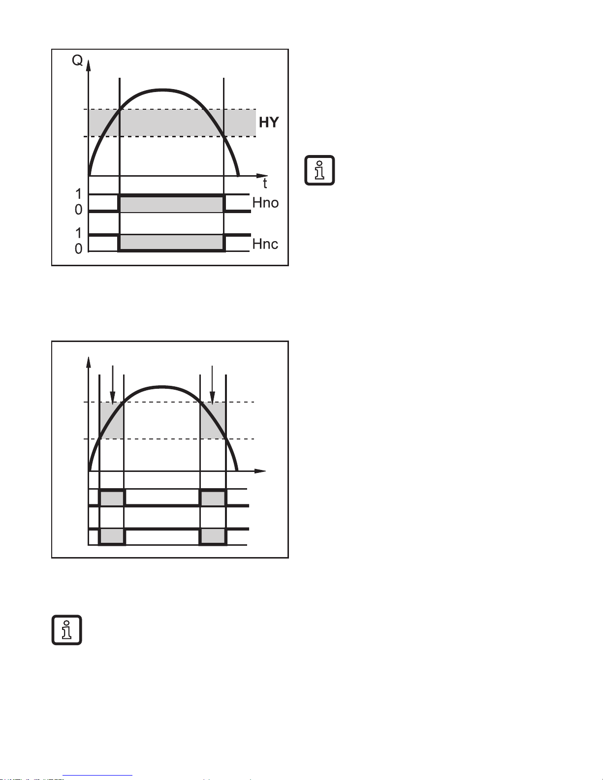
4.5.2 Window function
Normally open: [OUx] = [Fno]
Normally closed: [OUx] = [Fnc]
The width of the window can be set by
means of the difference between SPx
and rPx�
SPx = upper value
rPx = lower value
Example of volumetric flow monitoring
FE = window
When set to the window function the set and reset points have a fixed hysteresis of 0�25 % of the final value of the measuring range� This keeps the
switching status of the output stable if the volumetric flow varies slightly�
9
UK
4.6 Volumetric flow or temperature monitoring / analogue
function
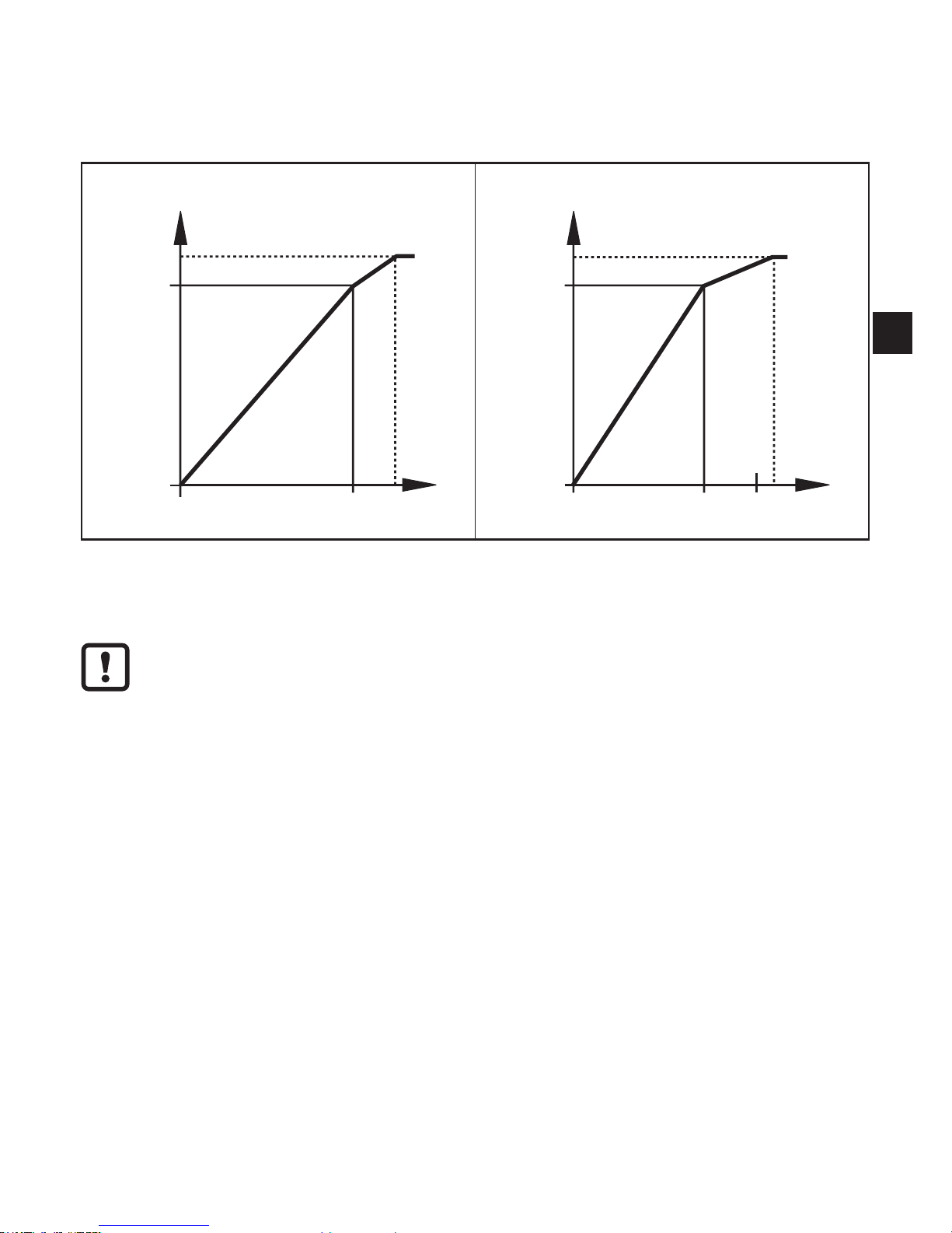
4.6.1 Voltage output 0 ... 10 V (example volumetric flow monitoring)
Factory setting Measuring range scaled
U [V]
10
0
0 MEW Q
U [V]
10
0
0 MEWAEPASP Q
MEW = final value of the measuring range
ASP = analogue start point: determines at which measured value the output signal is 4 mA
AEP =
analogue end point: determines at which measured value the output signal is 20 mA�
Minimum distance between ASP and AEP = 20 % of the measuring range�
In the set measuring range the output signal is between 0 and 10V�
For an output signal > 10 V the flow quantity is above the final value of the meas-
uring range�
10
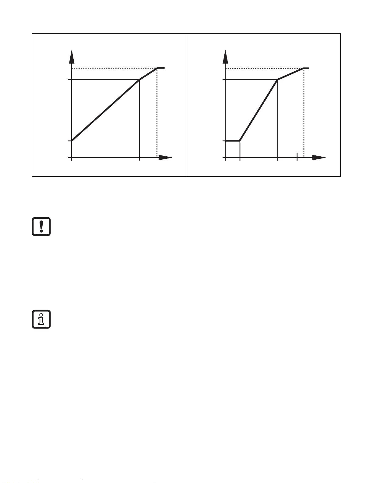
4.6.2 Current output 4 ... 20 mA (example volumetric flow monitoring)
Factory setting Measuring range scaled
I [mA]
20
4
0 MEW Q
I [mA]
20
4
0 MEWAEPASP Q
MEW = final value of the measuring range
ASP = analogue start point: determines at which measured value the output signal is 4 mA
AEP =
analogue end point: determines at which measured value the output signal is 20 mA�
Minimum distance between ASP and AEP = 20 % of the measuring range�
In the set measuring range the output signal is between 4 and 20 mA�
For an output signal > 20 mA the flow quantity is above the final value of the
measuring range�
4.7 Start-up delay
The start-up delay dST influences the switching outputs of the volumetric
flow monitoring�
If the start-up delay is active (dST > 0), note: as soon as the volumetric flow
exceeds 0�5 % of the final value of the measuring range, the following processes
are carried out:
> The start-up delay is activated�
> The outputs switch as programmed:
ON for NO function, OFF for NC function�
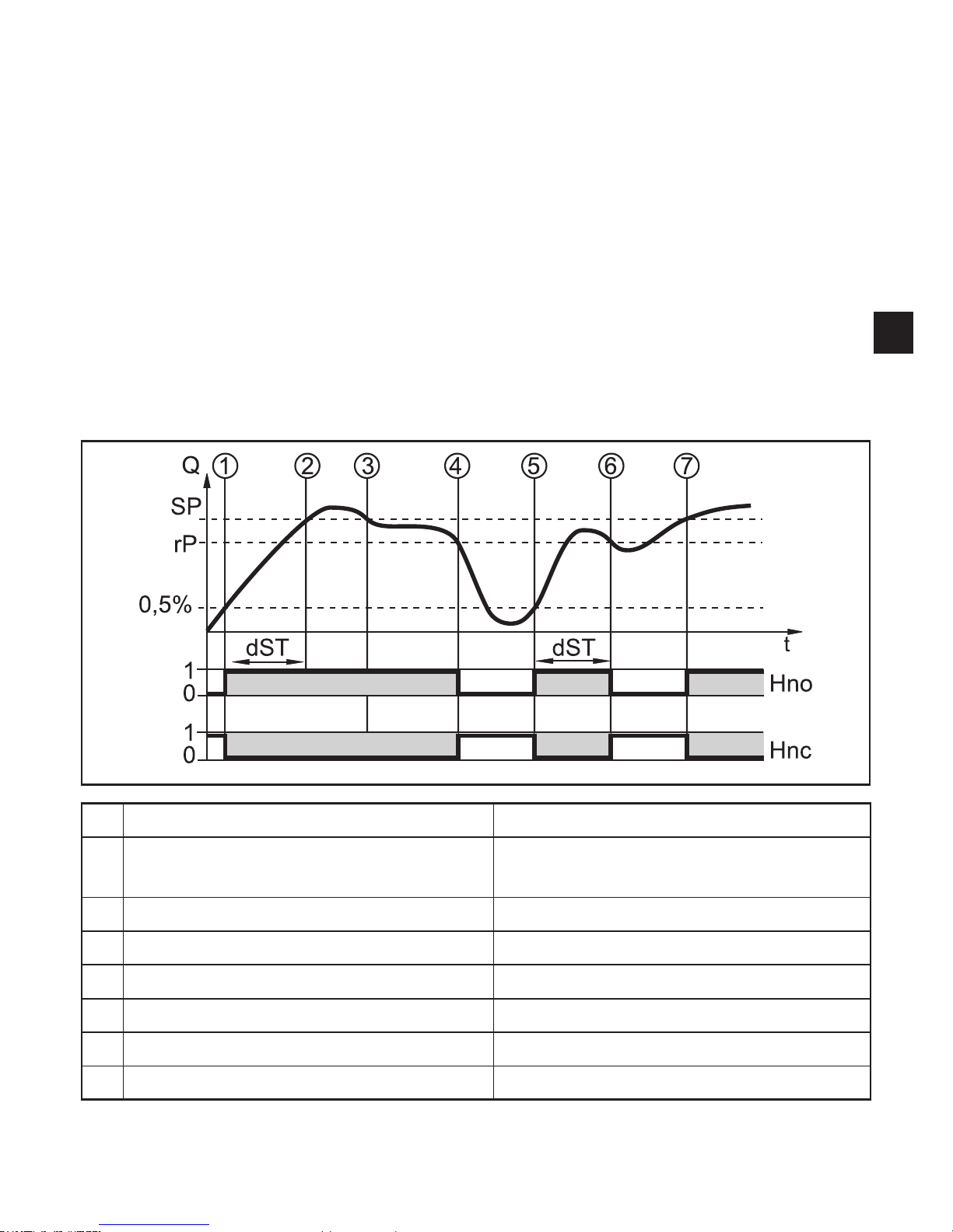
11
UK
After the start of the start-up delay there are 3 options:
1� The volumetric flow increases quickly and reaches the set point / good range
within dST�
> Outputs remain active�
2� The volumetric flow increases slowly and does not reach the set point /good
range within dST�
> Outputs are reset�
3� Volumetric flow quantity falls below 0�5 % of the final value of the measuring
range within [dST]�
> Outputs are reset at once; dST is stopped�
Example: dST for hysteresis function
Condition Reaction
1
Volumetric flow quantity Q reaches 0�5
% of VMR
dST starts, output becomes active
2 dST elapsed, Q reached SP output remains active
3 Q below SP but above rP output remains active
4 Q below rP output is reset
5 Q reaches again 0�5 % of VMR dST starts, output becomes active
6 dST elapsed, Q has not reached SP output is reset
7 Q reaches SP output becomes active
 Loading...