

IFM Electronic SM9x04, SM2x04 Operating Instructions Manual
Operating instructions
Magnetic-inductive
flow meter
SM9x04
SM2x04
UK
80223777 / 00 05 / 2016

Contents
1 Preliminary note ��������������������������������������������������������������������������������������������������� 4
1�1 Symbols used ������������������������������������������������������������������������������������������������4
1�2 Warning signs used ���������������������������������������������������������������������������������������4
2 Safety instructions �����������������������������������������������������������������������������������������������4
3 Functions and features ����������������������������������������������������������������������������������������5
4 Function ��������������������������������������������������������������������������������������������������������������� 6
4�1 Processing of the measured signals ��������������������������������������������������������������6
4�2 Direction of flow ���������������������������������������������������������������������������������������������6
4�2�1 Determination of the direction of flow (Fdir) ������������������������������������������6
4�3 Consumed quantity meter �����������������������������������������������������������������������������6
4�4 Empty pipe detection �������������������������������������������������������������������������������������7
4�5 Analogue function ������������������������������������������������������������������������������������������7
4�6 Measured value damping (dAP) ��������������������������������������������������������������������9
4�7 Low flow cut-off (LFC) ������������������������������������������������������������������������������������9
4�8 Simulation ������������������������������������������������������������������������������������������������������ 9
4�9 IO-Link �����������������������������������������������������������������������������������������������������������9
5 Installation����������������������������������������������������������������������������������������������������������10
5�1 Recommended installation locations �����������������������������������������������������������10
5�2 Not recommended installation position �������������������������������������������������������� 11
5�3 Grounding ���������������������������������������������������������������������������������������������������� 12
5�4 Installation in pipes ��������������������������������������������������������������������������������������13
6 Electrical connection ������������������������������������������������������������������������������������������ 14
7 Operating and display elements ������������������������������������������������������������������������14
8 Menu ������������������������������������������������������������������������������������������������������������������ 15
8�1 Process value display ���������������������������������������������������������������������������������� 15
8�2 Main menu, Extended functions ������������������������������������������������������������������16
8�3 Basic settings ����������������������������������������������������������������������������������������������18
8�4 Min/max memory – Empty pipe – Simulation ����������������������������������������������20
9 Set-up ����������������������������������������������������������������������������������������������������������������21
10 Parameter setting ��������������������������������������������������������������������������������������������22
10�1 Parameter setting in general ���������������������������������������������������������������������23
10�1�1 Switching between the menu levels �������������������������������������������������24
2

10�1�2 Locking / unlocking ���������������������������������������������������������������������������24
10�1�3 Timeout ��������������������������������������������������������������������������������������������� 24
10�2 Setting the analogue value for temperature ����������������������������������������������24
10�3 Setting the analogue value for volumetric flow ������������������������������������������24
10�4 User settings (optional) ������������������������������������������������������������������������������25
10�4�1 Setting of the standard unit of measurement for temperature ���������� 25
10�4�2 Setting of the standard unit of measurement for volumetric flow ������25
10�4�3 Configuration of the standard display ����������������������������������������������� 25
10�4�4 Changing the direction of the flow rate measurement ���������������������� 25
10�4�5 Setting of measured value damping �������������������������������������������������25
10�4�6 Setting of the error behaviour of the outputs ������������������������������������25
10�4�7 Activating / deactivating empty pipe detection ���������������������������������� 26
10�4�8 Time-delay empty pipe detection ������������������������������������������������������ 26
10�4�9 Setting of the empty pipe detection ��������������������������������������������������26
10�4�10 Setting of the low flow cut-off ���������������������������������������������������������� 26
10�5 Service functions ���������������������������������������������������������������������������������������26
10�5�1 Reading the min/max values for the volumetric flow ������������������������26
10�5�2 Reading the min/max values for the temperature �����������������������������27
10�5�3 Simulation menu ������������������������������������������������������������������������������� 27
10�5�4 Resetting all parameters to factory setting ���������������������������������������27
10�5�5 Activating the IO-Link communication interface ��������������������������������27
11 Operation ���������������������������������������������������������������������������������������������������������28
11�1 Reading the process value ������������������������������������������������������������������������28
UK
11�2 Reading the parameter value ���������������������������������������������������������������������28
12 Troubleshooting �����������������������������������������������������������������������������������������������29
13 Technical data �������������������������������������������������������������������������������������������������� 30
14 Factory setting �������������������������������������������������������������������������������������������������31
3
1 Preliminary note
1.1 Symbols used
► Instruction
> Reaction, result
[…] Designation of keys, buttons or indications
→ Cross-reference
Important note
Non-compliance can result in malfunction or interference�
Information
Supplementary note�
1.2 Warning signs used
CAUTION
Warning of personal injury�
Slight reversible injuries may result�
2 Safety instructions
• Please read this document prior to set-up of the unit� Ensure that the product is
suitable for your application without any restrictions�
• If the operating instructions or the technical data are not adhered to, personal
injury and/or damage to property can occur�
• Improper or non-intended use may lead to malfunctions of the unit or to unwanted effects in your application� That is why installation, electrical connection, set-up, operation and maintenance of the unit must only be carried out by
qualified personnel authorised by the machine operator�
• In order to guarantee the correct condition of the device for the operating time it
is necessary to use the device only for media to which the wetted materials are
sufficiently resistant (→ Technical data).
• The responsibility whether the measurement devices are suitable for the
respective application lies with the operator� The manufacturer assumes no
liability for consequences of misuse by the operator� Improper installation and
use of the devices result in a loss of the warranty claims�
4

• For medium temperatures above 50 °C (122 °F) some parts of the housing can
heat up to over 65 °C (149 °F)� Moreover, during installation or in case of a fault
(e�g� housing damage) media under high pressure or hot media can leak from
the system� To avoid personal injury, take the following measures:
► Install the unit according to the applicable rules and regulations�
► Ensure that the system is free of pressure during installation�
► Protect the housing against contact with flammable substances and
unintentional contact� To do so, equip the unit with suitable protection (e�g�
protective cover)�
► Do not press the pushbuttons manually; instead use another object (e�g�
UK
ballpoint pen)�
• This is a class A product� This unit may cause radio interference in domestic
areas� If required, take appropriate EMC screening measures�
3 Functions and features
Pressure Equipment Directive (PED): The units comply with section 3, article 3 of
the Directive 97/23/EC and must be designed and manufactured for non-superheated liquids of group 2 fluids in accordance with the sound engineering practice�
The unit monitors liquid media�
The unit detects the 3 process categories volumetric flow quantity, consumed
quantity and medium temperature�
Application area
Conductive liquids with the following properties:
• Conductivity: ≥ 20 µS/cm
• Viscosity: < 70 mm
2
/s at 40 °C; < 70 cST at 104 °F
5

4 Function
• The unit detects the flow based on the magnetic-inductive volumetric flow
measuring principle�
• The unit also detects the medium temperature�
• It features an IO-Link interface�
• The unit displays the current process value�
4.1 Processing of the measured signals
The unit generates 2 output signals according to the parameter setting�
OUT1/IO-Link: Parameter setting
- Analogue signal for temperature (→ 10.2)
- Communication interface (→ 10.5.5)
OUT2: Parameter setting
- Analogue signal for volumetric flow quantity (→ 10.3)
4.2 Direction of flow
In addition to the flow velocity and the volumetric flow quantity, the unit also detects the direction of flow�
4.2.1 Determination of the direction of flow (Fdir)
An arrow with the text "flow direction" on the unit indicates the positive flow direction� The flow direction can be inversed (→ 10.4.4)�
► Use the supplied label to mark the changed flow direction (new positive
direction of flow)�
Flow... Process value display
corresponds to the marked flow direction + (positive)
against the marked flow direction - (negative)
4.3 Consumed quantity meter
The unit has an internal mass flow meter which continuously totals the volumetric
flow quantity� The total corresponds to the current consumed quantity�
• The quantity meter takes account of the flow direction for totalisation:
6

- Flow according to the marked flow direction (arrow "flow direction"): meter
adds�
- Flow against the marked flow direction: meter subtracts�
The meter saves the totalled consumed quantity every 10 minutes� After
a power failure this value is available as the current meter reading� So the
possible data loss can be maximum 10 minutes�
The current meter reading can be evaluated via an external parameter setting
software (→ 10.5.5 Activating the IO-Link communication interface)�
UK
4.4 Empty pipe detection
The unit detects when the two electrodes are not wetted by the medium� The
empty pipe detection can be activated or deactivated (→ 10.4.7)� If it is active and
the pipe is empty, the unit reacts as follows:
> [SEnS] is indicated in the display�
> The flow is set to zero�
The empty pipe detection can be set as time-depending or not time depending (→
10�4�8)�
4.5
Analogue function
• The unit provides an analogue signal that is proportional to the volumetric flow
quantity and the medium temperature�
• Within the measuring range the analogue signal is 4���20 mA�
• If the measured value is outside the measuring range or in the event of an
internal error, the current signals indicated in Figure 1 are provided�
• The measuring range is scalable:
[ASP] determines at which measured value the output signal is 4 mA�
[AEP] determines at which measured value the output signal is 20 mA �
Minimum distance between [ASP] and [AEP] = 20 % of the final value of
the measuring range�
7
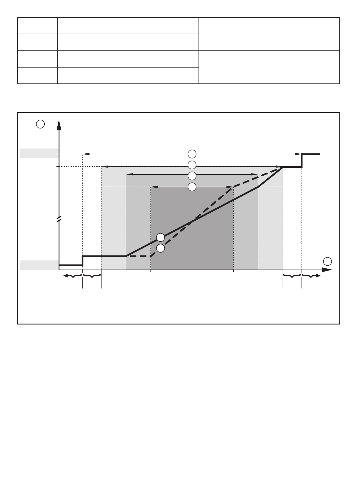
MAW Initial value of the measuring range
For non-scaled measuring range
MEW Final value of the measuring range
ASP Analogue start point
AEP Analogue end point
Table 1: Definitions
1
[mA]
FOU=On
22
21,5
20
3
4
5
6
(= factory setting)
For scaled measuring range
5*
6*
4
3,5FOU=OFF
cr.UL UL OL cr.OL
-130
-120Q [% MEW]
-50
MEWMAW AEPASP
1000 130
120
2
[°C]T -40 -20 80 100 110
[°F]-40 -4 176 212 230-58
Figure 1: Characteristics of the analogue output according to the standard IEC 60947-5-7�
Q: Flow (a negative flow value means flow against the marked flow direction)
T: Temperature
UL: Below the display range
OL: Above the display range
cr�UL: Below the detection zone (error)
cr�OL: Above the detection zone (error)
FOU=On: Default setting at which the analogue signal goes to the upper final value in
case of an error�*
FOU=OFF: Default setting at which the analogue signal goes to the lower final value in
case of an error�*
* The type of error is displayed: cr�UL, cr�OL, Err (→ 12)�
8

1
Analogue signal
2
3
4
5
5
*
6
6
*
Analogue signal in the measuring range
Measured value (flow or temperature)
Detection zone
Display range
Measuring range
with factory setting
Scaled measuring range
Analogue signal for scaled measuring
range
4.6 Measured value damping (dAP)
The damping time allows to set after how many seconds the output signal has
reached 63 % of the final value if the flow value changes suddenly� The set damping time stabilises the outputs, the display and the process value transfer via the
IO-Link interface� The signals [UL] and [OL] (→ 12 Troubleshooting) are defined
UK
under consideration of the damping time�
4.7 Low flow cut-off (LFC)
With the function Low Flow cut-off small volumetric flow quantities can be ignored
(→ 10.4.10)� Flows below the LFC value are evaluated by the sensor as standstill
(Q = 0)�
4.8 Simulation
With this function flow and temperature values can be simulated� (→ 10.5.3)� The
outputs operate as previously set�
4.9 IO-Link
This unit has an IO-Link communication interface�
With a PC, suitable IO-Link software and an IO-Link adapter cable communication
is possible when the system is not in operation�
The IODDs necessary for the configuration of the unit, detailed information about
process data structure, diagnostic information, parameter addresses and the
necessary information about the required IO-Link hardware and software can be
found at www�ifm�com�
► The memory plug (E30398) must not remain connected to the unit,
because it falsifies the analogue output� It must only be connected for
parameter setting�
9
5 Installation
► Avoid deposits, accumulated gas and air in the pipe system�
The unit can be installed irrespective of the orientation if the following is
ensured:
- No air bubbles can form in the pipe system�
- The pipes are always completely filled�
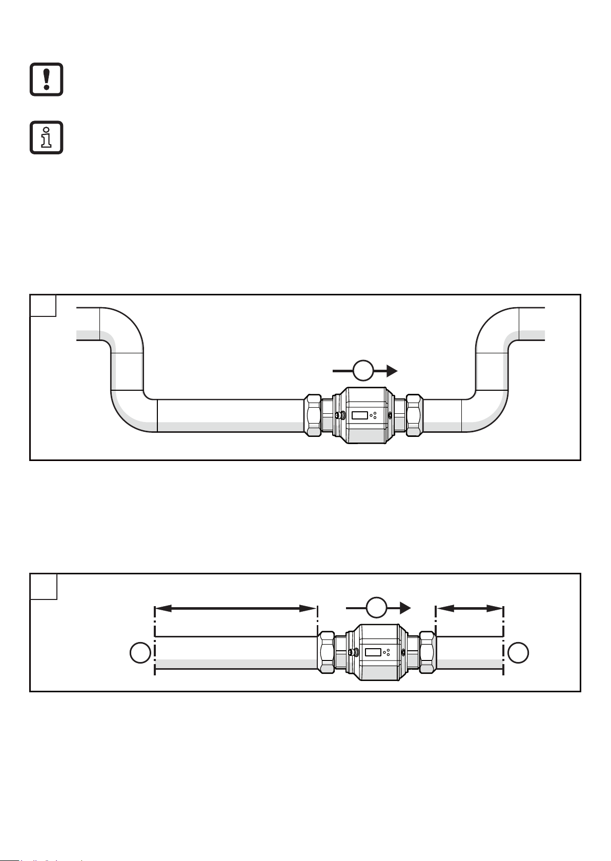
5.1 Recommended installation locations
Example of an optimised installation:
1
F
► Install the unit so that the measuring pipe is completely filled�
► Arrange for inlet and outlet pipe lengths� Disturbances caused by bends,
valves, reductions, etc� are compensated for� It applies in particular: no shut-off
and control devices are allowed directly in front of the unit�
2
5 x D
F
S S
2 x D
S = disturbance; D = pipe diameter; F = flow direction
10
 Loading...