

Page 1
Operating instructions
Magnetic-inductive flow meter
SM6x04
SM7x04
SM8x04
UK
80223776 / 00 11 / 2018
Page 2

Contents
1 Preliminary note ��������������������������������������������������������������������������������������������������� 3
2 Safety instructions �����������������������������������������������������������������������������������������������3
3 Functions and features ����������������������������������������������������������������������������������������4
4 Function ��������������������������������������������������������������������������������������������������������������� 5
4�1 Processing of the measured signals ��������������������������������������������������������������5
4�2 Direction of flow ���������������������������������������������������������������������������������������������5
4�3 Analogue function ������������������������������������������������������������������������������������������6
4�4 Measured value damping (dAP) ��������������������������������������������������������������������7
5 Mounting �������������������������������������������������������������������������������������������������������������� 8
5�1 Recommended installation position ��������������������������������������������������������������� 8
5�2 Not recommended installation position ����������������������������������������������������������9
5�3 Grounding ���������������������������������������������������������������������������������������������������� 10
5�4 Installation in pipes �������������������������������������������������������������������������������������� 11
6 Electrical connection ������������������������������������������������������������������������������������������ 12
7 Operating and display elements ������������������������������������������������������������������������13
8 Menu ������������������������������������������������������������������������������������������������������������������ 14
9 Set-up ����������������������������������������������������������������������������������������������������������������16
10 Parameter setting ��������������������������������������������������������������������������������������������16
10�1 Parameter setting in general ���������������������������������������������������������������������17
10�1�1 Change to the menu "Extended functions" ��������������������������������������� 17
10�1�2 Locking / Unlocking ��������������������������������������������������������������������������17
10�1�3 Timeout ��������������������������������������������������������������������������������������������� 18
10�2 Scaling of the analogue value for temperature (OUT1) ����������������������������� 18
10�3 Scaling of the analogue value for volumetric flow (OUT2) ������������������������18
10�4 User settings (optional) ������������������������������������������������������������������������������18
10�4�1 Determine the standard unit of measurement for volumetric flow ����18
10�4�2 Determine the standard unit of measurement for temperature ���������18
10�4�3 Standard display ������������������������������������������������������������������������������� 18
10�4�4 Measured value damping �����������������������������������������������������������������18
10�4�5 Error behaviour of the outputs ����������������������������������������������������������19
10�5 Service functions ���������������������������������������������������������������������������������������19
10�5�1 Read min/max values �����������������������������������������������������������������������19
2
Page 3
10�5�2 Restoring the factory settings �����������������������������������������������������������19
11 Operation ���������������������������������������������������������������������������������������������������������19
11�1 Reading the process value ������������������������������������������������������������������������19
11�2 Changing the process value display in the RUN mode������������������������������20
11�3 Reading the set parameters �����������������������������������������������������������������������20
12 Troubleshooting �����������������������������������������������������������������������������������������������21
13 Technical data �������������������������������������������������������������������������������������������������� 21
14 Factory setting ������������������������������������������������������������������������������������������������22
1 Preliminary note
► Instructions
UK
> Reaction, result
[…] Designation of keys, buttons or indications
→ Cross-reference
Important note
Non-compliance may result in malfunction or interference�
Information
Supplementary note�
CAUTION
Warning of personal injury�
Slight reversible injuries may result�
2 Safety instructions
• The device described is a subcomponent for integration into a system�
- The manufacturer of the system is responsible for the safety of the system�
- The system manufacturer undertakes to perform a risk assessment and to
create a documentation in accordance with legal and normative requirements
to be provided to the operator and user of the system� This documentation
must contain all necessary information and safety instructions for the operator,
the user and, if applicable, for any service personnel authorised by the manufacturer of the system�
3
Page 4

• Read this document before setting up the product and keep it during the entire
service life�
• The product must be suitable for the corresponding applications and environmental conditions without any restrictions�
• Only use the product for its intended purpose (→ Functions and features).
• Only use the product for permissible media (→ Technical data).
• If the operating instructions or the technical data are not adhered to, personal
injury and/or damage to property may occur�
• The manufacturer assumes no liability or warranty for any consequences
caused by tampering with the product or incorrect use by the operator�
• Installation, electrical connection, set-up, operation and maintenance of the unit
must be carried out by qualified personnel authorised by the machine operator�
• Protect units and cables against damage�
3 Functions and features
The unit monitors liquid media� It detects the 2 process categories volumetric flow
and medium temperature�
Pressure Equipment Directive (PED)
The units comply with the Pressure Equipment Directive and are designed and
manufactured for group 2 fluids in accordance with the sound engineering practice� Use of group 1 fluids on request�
Application area
Conductive liquids with the following properties:
• Conductivity: ≥ 20 µS/cm
• Viscosity: < 70 mm
2
/s at 40 °C; < 70 cSt at 104 °F
4
Page 5
4 Function
• The unit detects the flow based on the magnetic-inductive volumetric flow
measuring principle�
• The unit also detects the medium temperature�
• The unit displays the current process value�
4.1 Processing of the measured signals
The unit generates 2 output signals according to the parameter settings:
OUT1: Parameter setting
UK
- Analogue signal for temperature → 10.2
OUT2: Parameter setting
- Analogue signal for volumetric flow quantity → 10.3
4.2 Direction of flow
In addition to the flow velocity and the volumetric flow quantity, the unit also
detects the direction of flow�
An arrow with the text "flow direction" on the unit indicates the positive flow
direction�
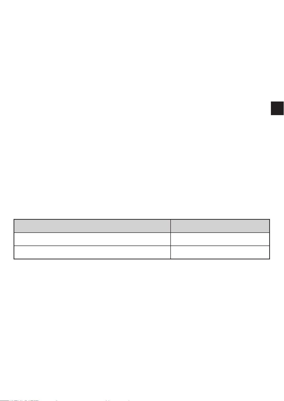
Flow... Process value display
corresponds to the marked flow direction + (positive)
against the marked flow direction - (negative)
Only positive process values are processed for the signal output�
5
Page 6
4.3
Analogue function
• The unit provides an analogue signal that is proportional to the volumetric flow
quantity and the medium temperature�
• Within the measuring range the analogue signal is 4���20 mA�
• If the measured value is outside the measuring range or in the event of an
internal error, the current signals indicated in Figure 1 are provided�
• The measuring range is scalable:
[ASP] determines at which measured value the output signal is 4 mA�
[AEP] determines at which measured value the output signal is 20 mA�
Minimum distance between [ASP] and [AEP] = 20 % of the final value of
the measuring range�
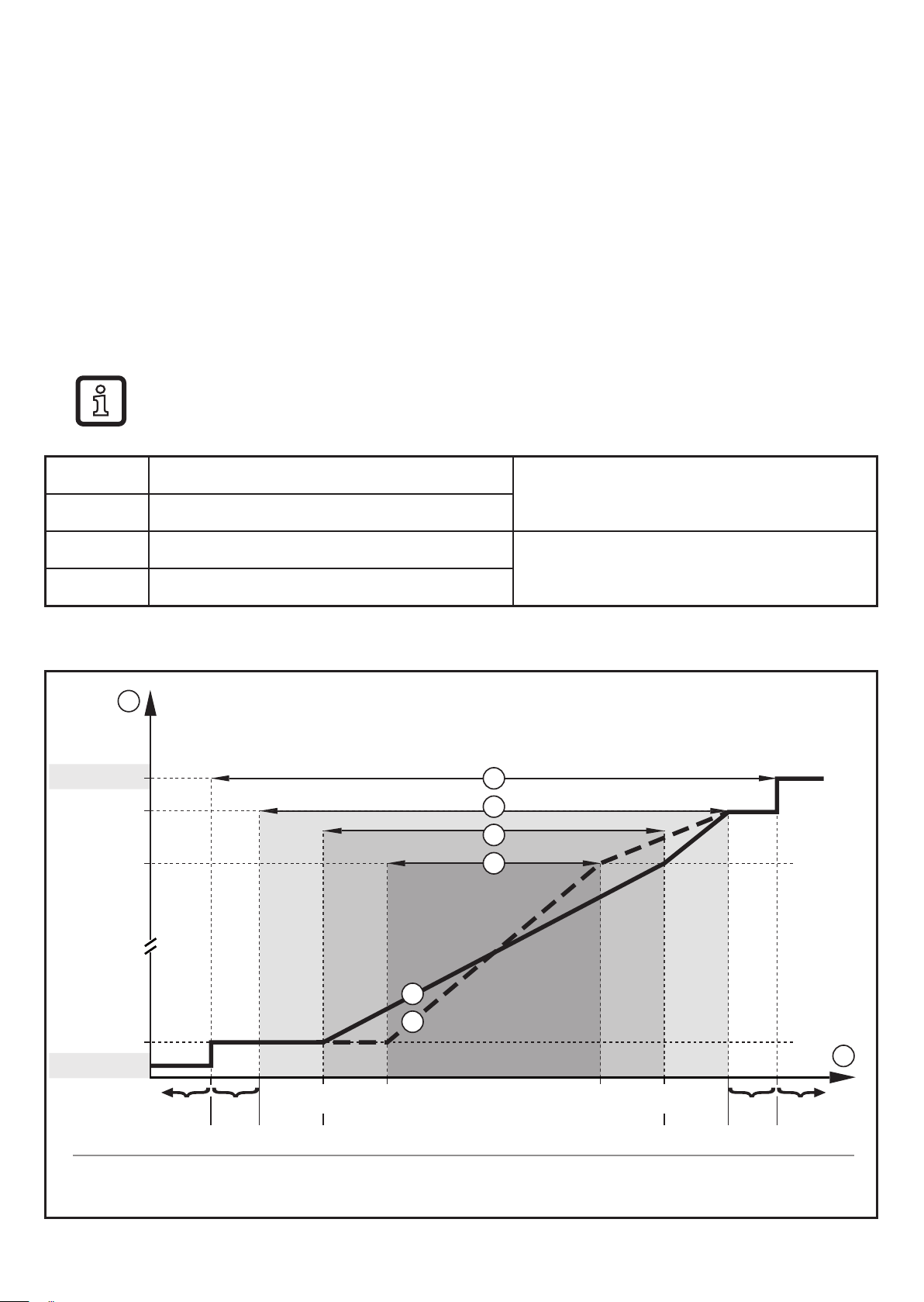
MAW Initial value of the measuring range
MEW Final value of the measuring range
ASP Analogue start point
AEP Analogue end point
Table 1: Definitions
1
[mA]
FOU=On
22
21,5
20
3
4
5
6
For non-scaled measuring range
(= factory setting)
For scaled measuring range
5*
6*
4
3,5FOU=OFF
Err UL OL Err
Q [% MEW]
MEWMAW AEPASP
1000-120-130 130
120
2
[°C]T -20-40-50 80 100 110
[°F]176-4-58 -40 212 230
Figure 1: Characteristics of the analogue output according to the standard IEC 60947-5-7�
6
Page 7

Q: Flow (a negative flow value means flow against the marked flow direction)
1
2
3
4
5
5
*
6
6
*
T: Temperature
UL: Below the display range
OL: Above the display range
Err: The unit is in the error state
FOU=On: Default setting at which the analogue signal goes to the upper final value in
case of an error�
FOU=OFF: Default setting at which the analogue signal goes to the lower final value in
case of an error�
Analogue signal
Measured value (flow or temperature)
Detection zone
Display range
Measuring range
Analogue signal in the measuring range
with factory setting
UK
Scaled measuring range
Analogue signal for scaled measuring
range
4.4 Measured value damping (dAP)
The damping time allows to set after how many seconds the output signal has
reached 63 % of the final value if the flow value changes suddenly� The set damping time stabilises the outputs and the display� The signals [UL] and [OL] (→ 12)
are defined under consideration of the damping time�
7
Page 8

5 Mounting
3 x D
1 x D
CAUTION
If the medium temperature is above 50 °C (122 °F) parts of the housing can
increase in temperature to over 65 °C (149 °F)�
> Risk of burns�
► Protect the housing against contact with flammable substances and
unintentional contact�
► Attach the supplied warning label to the sensor cable�
► Ensure that the system is free of pressure during installation�
► Ensure that no media can leak at the mounting location during installa-
tion�
► Avoid deposits, accumulated gas and air in the pipe system�
The unit can be installed independently of the orientation if the following is
ensured:
- No air bubbles can form in the pipe system�
- The pipes are always completely filled�
5.1 Recommended installation position
► Install the unit so that the measuring pipe is always completely filled�
► Arrange for inlet and outlet pipe lengths� Disturbances caused by bends,
valves, reductions, etc� are compensated for� It applies in particular: no shut-off
and control devices are allowed directly in front of the unit�
F
S
S = disturbance (e�g� shut-off / control device, pump, bends)
D = pipe diameter
F = direction of flow
8
S
Page 9

► Install in front of or in a rising pipe�
F
5.2 Not recommended installation position
► Avoid the following installation positions:
F
UK
F
Directly in front of a falling pipe� In a falling pipe�
F
9
Page 10

F
Directly in front of
the spout of the pipe�
F
On the suction side of a pump�
F
At the highest point of the pipe system�
F = flow direction
5.3 Grounding
If installed in an ungrounded pipe system (e�g� plastic pipes), the unit must
be grounded (functional earth)�
Ground brackets for the M12 connector are available as accessories
→ www.ifm.com.
10
Page 11
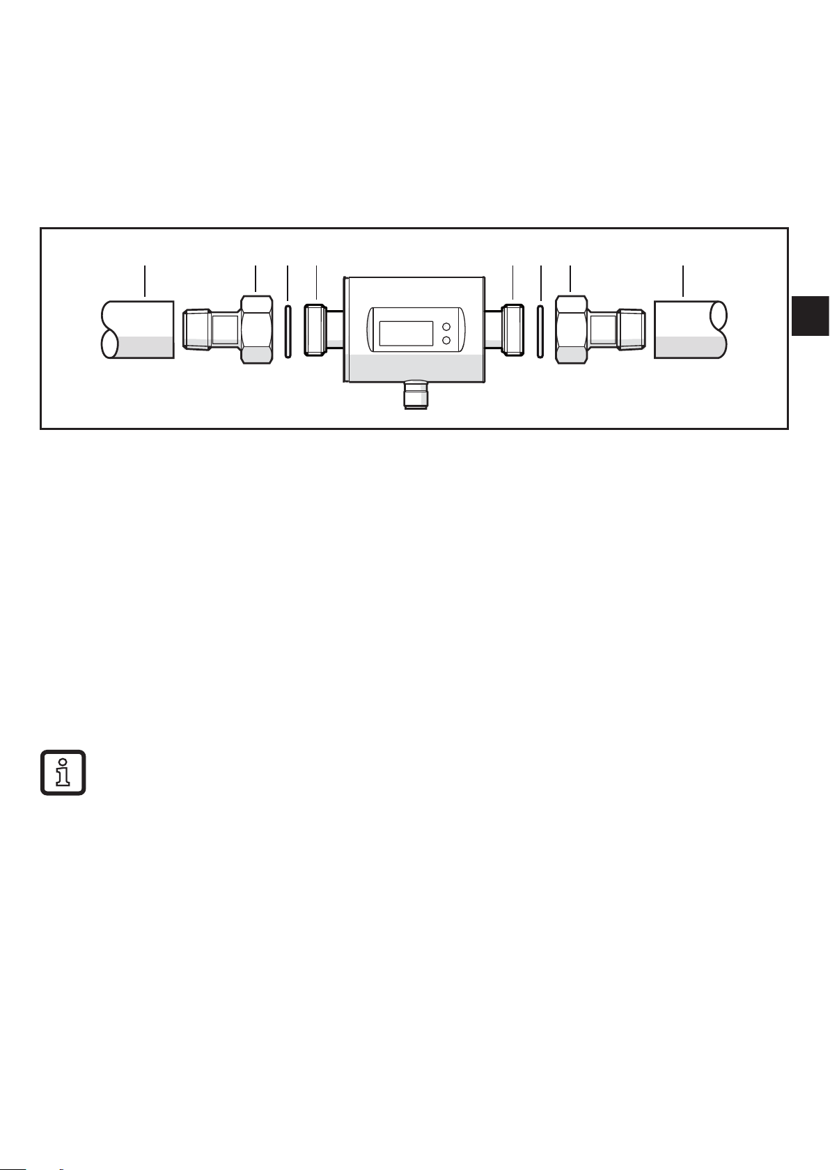
5.4 Installation in pipes
The units with a G thread can be installed in the pipes using adapters�
Information about the available mounting accessories at www�ifm�com�
A correct fit of the unit and ingress resistance of the connection are only ensured
using ifm adapters�
A AD DC CB B
UK
1� Grease the threads of the process connection, adapter and sensor� Use a
lubricating paste which is suitable and approved for the application�
2� Screw the adapter (B) into the pipe (A)�
3� Place the seals (C) and install the unit according to the marked flow direction�
4� Screw the adapter (B) with the threads (D) until it is hand-tight�
5� Tighten the two adapters in opposite direction (Tightening torque: 30 Nm)�
After installation air bubbles in the system can affect the measurement�
► Corrective measures: Rinse the system after installation for ventilation�
In case of horizontal installation:
As a result of design requirements a small quantity of the medium always
remains in the measuring channel after switching off the pump�
11
Page 12

6 Electrical connection
The unit must be connected by a qualified electrician�
The national and international regulations for the installation of electrical
equipment must be adhered to�
Voltage supply according to EN 50178, SELV, PELV�
► Disconnect power�
► Connect the unit as follows:
2 1
43
BK: black
BN: brown
BU: blue
WH: white
BN
1
WH
2
BK
4
BU
3
+
L
OUT2
OUT1
L
Colours to DIN EN 60947-5-2
Pin 1 L+
Pin 3 L-
Pin 4 (OUT1) Analogue signal for temperature
Pin 2 (OUT2) Analogue signal for volumetric flow quantity
12
Page 13

7 Operating and display elements
UK
1-8: Indicator LEDs
• LEDs 1-6: Unit of the currently represented numerical value → 11.1 Reading the process
value
• LED 7-8: not used
9: Alphanumeric display, 4 digits
• Current volumetric flow quantity with setting [SELd] = FLOW
• Current medium temperature with setting [SELd] = TEMP
• Parameters and parameter values
10: [Mode/Enter] button
• Change from the RUN mode to the main menu
• Select parameters
• Acknowledge the set parameter value
11: [Set] button
• Change parameter values (hold button pressed)
• Change of the display unit in the normal operating mode (RUN mode)
13
Page 14
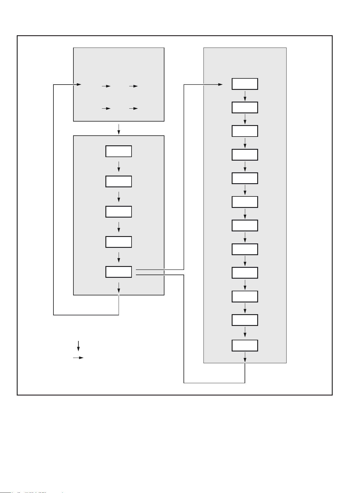
8 Menu
l/min °C / °Fm
gpm
gph
ASP1
AEP1
ASP2
3
/h
RUN
°C / °F
EF
Hi.F
Lo.F
Hi.T
Lo.T
FOU1
FOU2
dAP
AEP2
EF
[Mode / Enter]
[Set]
diS
uni.F
uni.T
SELd
rES
14
Page 15

Parameters Explanation and setting options
ASP1 Analogue start point for temperature on OUT1�
AEP1 Analogue end point for temperature on OUT1�
ASP2 Analogue start point for volumetric flow on OUT2�
AEP2 Analogue end point for volumetric flow on OUT2�
EF Extended functions: opening of the lower menu level�
Hi�F Maximum value memory for volumetric flow�
Hi�T Maximum value memory for temperature�
Lo�F Minimum value memory for volumetric flow�
Lo�T Minimum value memory for temperature�
FOU1 Behaviour of OUT1 in case of an internal fault:
OU, On, OFF (→ 10.4.5)�
FOU2 Behaviour of OUT2 in case of an internal fault:
OU, On, OFF (→ 10.4.5)�
dAP Measured value damping: damping constant in seconds�
diS Update rate and orientation of the display: d1���d3, rd1���rd3, OFF
(→ 10.4.3)�
uni�F Standard unit of measurement for volumetric flow
uni�T Standard unit of measurement for temperature
UK
SELd Standard measured variable of the display:
FLOW (volumetric flow value), TEMP (medium temperature)�
rES Restoring the factory settings�
15
Page 16

9 Set-up
After power on and expiry of the power-on delay time of approx� 5 s the unit is in
the RUN mode (= normal operating mode)� It carries out its measurement and
evaluation functions and generates output signals according to the set parameters�
During the power-on delay time the output signal is at 20 mA�
10 Parameter setting
Parameters can be set before installation or during operation�
If you change parameters during operation, this will influence the function�
► Ensure that there will be no malfunctions in your plant�
During parameter setting the unit remains in the operating mode� It continues to
monitor with the existing parameter until the parameter setting has been completed�
CAUTION
If the medium temperature is above 50 °C (122 °F) parts of the housing can
increase in temperature to over 65 °C (149 °F)�
> Risk of burns�
► Do not touch the device with your hands�
► Use another object (e�g� a ballpoint pen) to carry out settings on the unit�
16
Page 17

10.1 Parameter setting in general
1� Change from the RUN mode to the main menu and
selection of the requested parameter
2� Acknowledge the set parameter value [Set]
3� Change the setting mode [Set] > 5 s
4� Modification of the parameter value
- incrementally by pressing once
- continuously by keeping the button pressed
To reduce the value: let the display move to the
maximum setting value� Then the cycle starts
again at the minimum setting value�
5� Acknowledge the set parameter value [Mode/Enter]
6� Return to the RUN mode > 30 seconds (timeout)
[Mode/Enter]
[Set]
or
[Mode/Enter] until the RUN
UK
mode is reached�
10.1.1 Change to the menu "Extended functions"
1� Change from the RUN mode to the main menu and
selection of the parameter EF
2� Change to sub-menu EF [Set]
[Mode/Enter]
10.1.2 Locking / Unlocking
The unit can be locked electronically to prevent unintentional settings� On delivery:
not locked�
Locking ► Make sure that the unit is in the normal operating mode�
► Press [Mode/Enter] and [Set] simultaneously for 10 s until [Loc] is
displayed�
Unlocking ► Make sure that the unit is in the normal operating mode�
► Press [Mode/Enter] and [Set] simultaneously for 10 s until [uLoc] is
displayed�
17
Page 18

10.1.3 Timeout
If no button is pressed for 30 s during parameter setting, the unit returns to the
operating mode with unchanged values�
10.2 Scaling of the analogue value for temperature (OUT1)
► Select [ASP1] and set the value at which 4 mA is provided�
► Select [AEP1] and set the value at which 20 mA is provided�
10.3 Scaling of the analogue value for volumetric flow (OUT2)
► Select [ASP2] and set the value at which 4 mA is provided�
► Select [AEP2] and set the value at which 20 mA is provided�
10.4 User settings (optional)
10.4.1 Determine the standard unit of measurement for volumetric flow
► Select [uni�F] and set the unit of measurement: Lmin, m3h, GPm or GPh�
10.4.2 Determine the standard unit of measurement for temperature
► Select [uni�T] and set the unit of measurement: °C or °F�
10.4.3 Standard display
► Select [SELd] and define the standard unit of measurement
FLOW = display shows the current volumetric flow value in the standard unit of
measurement�
TEMP = display shows the current medium temperature in the standard unit of
measurement�
► Select [diS] and set the update rate and orientation of the display:
d1 = update of the measured values every 50 ms�
d2 = update of the measured values every 200 ms�
d3 = update of the measured values every 600 ms�
rd1, rd2, rd3 = display like d1, d2, d3; rotated by 180�
OFF = the display is switched off in the operating mode� The LEDs remain active
even if the display is deactivated� Error messages are displayed even if the display is
deactivated�
10.4.4 Measured value damping
► Select [dAP] and set the damping constant in seconds (τ value 63 %).
18
Page 19

10.4.5 Error behaviour of the outputs
► Select [FOUx] and set the value:
- On = The analogue signal goes to the upper fault value (→ 4.3)�
- OFF = The analogue value goes to the lower fault value (→ 4.3)�
- OU = The analogue signal corresponds to the measured value�
10.5 Service functions
10.5.1 Read min/max values
Read minimum or maximum measured values:
► Select Hi�x or Lo�x�
Hi�F = maximum volumetric flow, Lo�F = minimum volumetric flow
Hi�T = maximum temperature, Lo�T = minimum temperature
Delete memory:
► Select Hi�x or Lo�x�
UK
► Press and hold [Set] until [----] is displayed�
► Briefly press [Mode/Enter]�
It makes sense to delete the memories as soon as the unit operates under normal
operating conditions for the first time�
10.5.2 Restoring the factory settings
► Select [rES]�
► Press and hold [Set] until [----] is displayed�
► Briefly press [Mode/Enter]�
→ 14 Factory setting� We recommend taking down your own settings in that table
before carrying out a reset�
11 Operation
11.1 Reading the process value
The LEDs 1-6 signal which process value is currently displayed�
The process value to be displayed as standard (volumetric flow quantity or temperature) can be preset → 10.4.3 Standard display�
Moreover, a standard unit of measurement can be defined (volumetric flow →
10�4�1 and temperature → 10.4.2)�
19
Page 20

11.2 Changing the process value display in the RUN mode
► Briefly press [Set] in the RUN mode� Press the pushbutton to move to the next
display unit�
> The unit displays the current measured value in the selected display unit for
approx� 30 s, the corresponding indicator LED lights (→ 7)�
11.3 Reading the set parameters
► Briefly press [Mode/Enter] to scroll through the parameters�
► Briefly press [Set] when the requested parameter is displayed�
> The unit displays the corresponding parameter value� After about 15 s it returns
to the RUN mode�
20
Page 21

12 Troubleshooting
The unit has self-diagnostic options� It monitors itself automatically during operation�
Warnings and error states are displayed, even when the display is switched off�
Display Type Description Fault correction
Err Error Unit faulty / malfunction ► Replace the unit�
Err Error • Flow value < -130 % MEW or
> 130 % MEW�
• Temperature value < - 50 °C
(-58 °F) or > 110 °C (230 °F)�
No display Error • Supply voltage too low�
• Setting [diS] = OFF
Loc Warning Setting pushbuttons on the
unit locked, parameter change
rejected�
UL Warning Below the display range�
• Current value between
-130 % ��� -120 % MEW
• Temperature value between
-50���-40 °C (-58���-40 °F)�
► Check flow range /
temperature range�
► Check the supply voltage�
► Change the setting [diS] →
10�4�3
► Unlock the unit → 10.1.2
► Check flow range /
temperature range�
UK
OL Warning Display range exceeded�
• Current value between
120 % ��� 130 % MEW
• Temperature value between
100���110 °C (212���230 °F)�
MEW = final value of the measuring range
13 Technical data
Technical data and scale drawing at www�ifm�com�
► Check flow range /
temperature range�
21
Page 22

14 Factory setting
Parameter Factory setting User setting
ASP1 (TEMP) -20 °C
AEP1 (TEMP) 80 °C
ASP2 (FLOW) MAW
AEP2 (FLOW) MEW
FOU1 OFF
FOU2 OFF
dAP 3 s
diS d2
uni.F
SMxx04 : l/min
SMx404 : l/min
SMx604 : gpm
uni.T
SMxx04 : °C
SMx404 : °C
SMx604 : °F
SELd FLOW
MAW = Initial value of the measuring range
MEW = Final value of the measuring range
22
Technical data, approvals, accessories and further information at
www�ifm�com�
 Loading...